Skip to content
  • MySensors
  • OpenHardware.io
  • Categories
  • Recent
  • Tags
  • Popular
Skins
  • Light
  • Brite
  • Cerulean
  • Cosmo
  • Flatly
  • Journal
  • Litera
  • Lumen
  • Lux
  • Materia
  • Minty
  • Morph
  • Pulse
  • Sandstone
  • Simplex
  • Sketchy
  • Spacelab
  • United
  • Yeti
  • Zephyr
  • Dark
  • Cyborg
  • Darkly
  • Quartz
  • Slate
  • Solar
  • Superhero
  • Vapor

  • Default (No Skin)
  • No Skin
Collapse
Brand Logo
BearWithBeardB

BearWithBeard

@BearWithBeard
About
Posts
213
Topics
6
Shares
0
Groups
0
Followers
1
Following
0

Posts

Recent Best Controversial

  • What did you build today (Pictures) ?
    BearWithBeardB BearWithBeard

    Winter time is tinker time!

    mysensors-epd-node-clean.jpg

    This is a compact environmental sensor node with an E-Paper display. My goal was to have a decent screen-to-body ratio with a simple and minimalistic display, easy to read from a distance. It is the first design in which I did not use an ATmega MCU. It is also the first time that I used KiCAD instead of EAGLE, soldered no-lead SMD components and worked with an EPD.

    • It features a SHTC3 sensor to measure temperature and relative humidity and a VEML6030 to measure the ambient light, so that I can toggle lights or other appliances in the room based on temperature, humidity or light conditions.
    • I have also added a MEMS sensor (LIS3DH) to auto-detect the device orientation and rotate the EPD image accordingly and / or detect tap events to toggle between different display modes / data sets.
    • It can be powered directly from a 3V source or use the optional 3.3V boost circuit which accepts 1.5V or 3V sources.

    I finished soldering and testing all the components today and just started programming the rough "framework". Looks promising so far! But still lots to do, including finalizing the 3D printed enclosure. This is how it is supposed to look in the end:

    mysensors-epd-node-render2.jpg

    General Discussion

  • 💬 Connecting the Radio
    BearWithBeardB BearWithBeard

    Since I already (half-heartedly) posted drawings of some RFM modules I created a while ago in another thread, I might as well put a little RFM69 / RFM9x infographic or cheat sheet together and share it with everyone. It's supposed to give beginners a quick overview over the available MySensors-compatible HopeRF modules.

    If you guys mind that I included the MySensors logo and mascot, please let me know and I'll remove it ASAP.

    RFM Cheat Sheet.png

    Announcements

  • Where did everyone go?
    BearWithBeardB BearWithBeard

    The availability of inexpensive commercial products surely is a factor for less interest in DIY solutions like MySensors. Chinese companies are flooding another market once again. Just look at Xiaomi's Aqara and Mijia range of products and their compatible clones. They offer at least a dozen of different sensors and actors in neat little enclosures with either ZigBee or BLE connectivity, many of which are commonly available for much less than 10 USD a piece in sales.

    In this view I get frequently asked by friends and relatives why I keep "wasting" so much time building my own devices when I could just buy some like they do and integrate them into Home Assistant or HomeKit with the flick of a switch.

    I always respond to them that - apart from privacy and reliability concerns against devices with a forced internet connection, as has already been mentioned by some of you - I actually enjoy the whole process from prototyping electronics to managing a home server. It's a hobby and I learn new things through it. Three years ago, I could barely read basic circuit diagrams - here I am, comfortably soldering self-designed all-SMD PCBs, enjoying programming so much that I branched out into other areas and started developing web apps. I can at least attempt to repair faulty electronics - and have been successful at times - instead of throwing them away and wasting resources.

    The whole DIY process forces me to think about my requirements and constraints. To think about what I actually need instead of what I want or could buy to fill a hole.

    MySensors is fantastic for someone like me. It is fairly accessible with commonly available components, with the option for much more powerful hardware, if needed. Wireless communication can be remarkably reliable. Other than ESP-based devices, MySensors nodes can be incredibly energy efficient for battery use. It's not polluting my WiFi, nor invading my privacy through cloud services. And although you might say it has gotten quieter in the forum, there's still always someone around to help if you're stuck. It's just that MySensors is strictly DIY, as @monte pointed out. You can't just buy a commercial device, upload a MySensors sketch to it and be done.

    That's probably not the answer to the question where everyone went, but rather why not many new come in. Maybe it's a hindrance for new users these days? Because the "DIY aspect", that's now often obsolete, was just a necessary evil for many? Or, as my friends ask, why waste your time with that?

    I guess you either have to have a specific mindset and interest to pick this up as a hobby with some dedication, or your requirements are so specific that no commercial product suits them, so that the pressure to DIY is high enough to bring yourself to do so. If not, the big home automation youtubers may show you the convenient way to quick satisfaction.

    General Discussion

  • GUIDE - NRF5 / NRF51 / NRF52 for beginners
    BearWithBeardB BearWithBeard

    I just got my first NRF5 running. I'll note how I got it working in case any of you guys still have troubles:

    Setup

    • OS: Windows 10
    • Programmer: STM32 Blue Pill with the Black Magic Probe firmware
    • NRF5: EByte E73-TBB dev board with a E73-2G4M0S1B (NRF52832)
    • Environment: PlatformIO

    Instructions

    Load the Black Magic Probe firmware with stlink as the probe host onto Blue Pill. You can follow this guide.

    Connect your new BMP to the NRF52 module:

    BMP NRF52 Serial Port
    3V3 3V3
    GND GND
    A5 SWDCLK GDB Server
    B14 SWDIO GBD Server
    A2 RXI UART
    A3 TXO UART

    Note: A2 and A3 are not required for programming. This is how you'd wire up the BMP for "classic" serial debugging. You can use the BMP both for programming and serial communication - no need for a second FTDI module.

    Using the GNU Arm Embedded Toolchain, run arm-none-eabi-gdb in a console and enter the following commands to unlock the NRF52:

    target extended-remote BMP_GDB_SERVER_PORT
    mon swdp_scan
    attach N // N = number of "Nordic nRF52 Access Port" if there are several
    mon erase_mass
    detach
    

    From the two serial ports the BMP provides, you want to use the GDB Server for BMP_GDB_SERVER_PORT above. If Windows only provides generic names for both ("USB Serial Device" or something), the one with the lower number should (usually) be the right choice. If not, try the other one.

    Windows users also must prefix the port with \\.\ if the number is double-digit, e.g. \\.\COM13.

    Now you can start uploading sketches the usual way. Here's my minimal PlatformIO config:

    [env:nrf52_dk]
    platform = nordicnrf52
    board = nrf52_dk
    board_build.variant = generic
    framework = arduino
    upload_protocol = blackmagic
    lib_deps = 
    	548 ; MySensors
    

    And a minimal test sketch for MySensors:

    #include <Arduino.h>
    
    #define LED 17
    
    #define MY_RADIO_RF24
    #define MY_RADIO_NRF5_ESB
    #define MY_NODE_ID 182
    
    #define SKETCH_NAME "NRF52 Test"
    #define SKETCH_VERSION "0.1"
    
    #include <MySensors.h>
    
    #define CHILD_ID 1
    MyMessage msg(CHILD_ID, V_VAR1);
    
    void presentation()
    {
      sendSketchInfo(SKETCH_NAME, SKETCH_VERSION);
      present(CHILD_ID, S_CUSTOM);
    }
    
    void setup()
    {
      pinMode(LED, OUTPUT);
    }
    
    void loop()
    {
      static uint8_t num;
      send(msg.set(num));
      ++num;
      
      digitalWrite(LED, HIGH);
      wait(5000);
      digitalWrite(LED, LOW);
      wait(5000);
    }
    

    Works like a charm so far! Now, if you please excuse me, I have a whole new microprocessor family to explore. Fun times!

    Development

  • Finally, progress! (evidence based radio testing method) (and capacitors)
    BearWithBeardB BearWithBeard

    It's great to see that you are putting in the effort to thorougly test and optimize your setup. I like that! :+1:

    Now, I'm also not an EE myself - in fact, I consider myself as a beginner still, so please correct me if I'm wrong. The large (electrolytic) capacitor not only provides a good portion of the juice when it is quickly needed to keep the voltage level up, e.g. if the radio starts transmitting - it also smoothes low-frequency changes in the voltage, but their high-frequency characteristics are rather poor. To also decouple high-frequency noise, you'd want to add a small (ceramic) capacitor, typically 100nF, aswell. Together they provide a smoother voltage than just a single capacitor would. If the larger of the two is 10, 47 or 100 µF shouldn't matter too much, as long as the power source is able to keep up. Of course, if you go further into the details, there's much more to it.

    I provide all my NRF24 nodes with (at least!) 100µF of bulk capacity via electrolytic capacitors - even if I'm heavily space constrained, like on tiny coin cell based nodes. I also always add a 100nF ceramic as close to the radio as possible and usually also an additional 10µF ceramic right next to it. This setup is working great for me: my "NACK rate" is usually below 0.1%. For example, my outdoor weather station has sent 5072 messages over the last seven days, of which four failed to transmit initially (< 0.08%).

    I monitor the reliability of my nodes by simply checking the return value of send() and sending an error count if the transmission failed (ensuring that this message is successfully sent, or else I retry until it worked). All data is stored in a time-series database, so I can simply query the number of data points in a specific time frame as well as the number of reported errors.

    Troubleshooting nrf24l01+ radio

  • A tiny BME node - BME280 on ATtiny85
    BearWithBeardB BearWithBeard

    Short answer: unless you have absolutely no space left for an electrolytic capacitor, there's no reason to not use one.

    Long answer: Using an electrolytic capacitor or not when running off a CR2032 was a huge question for me when I was designing my window / door sensor nodes, because I assumed that their leakage current would be higher than the whole circuit consumes during sleep, resulting in a much lower battery life. The first thing I did was soldering up some prototypes (m328p, generic nrf24), one with a good quality, branded electrolytic capacitor, one with a random chinese cap and one without one and installed all on the same door, so I could compare them. I kept them running for almost a year until recently.

    Unfortunately I lost my InfluxDB instance with the recorded data, but here's the gist: The units with a capacitor didn't drain the coin cell faster than the one without. In the end, the delta between the three batteries were merely 30mV, which is nothing considering the runtime. They're still at ~3.05V. Whenever I looked at the graphs to see how reliable they were, I couldn't find any issues - if they triggered a state change, they all successfully reported the event. Then again, they were installed on the door of the same room the gateway was in.

    But here's the catch: When I received my custom PCBs, I installed two sensors on the same window on the other side of the house, one with and one without a capacitor - again, to compare them, but this time in a "real world" scenario. With #define MY_RF24_PA_LEVEL RF24_PA_HIGH, which is the default setting, the node without the cap failed to reach the gateway reliably, while the other one had no problem at all. Switching to RF24_PA_LOW resulted in both units unable to communicate with the gateway, they were simply too far away. Contrary, keeping the PA level up and soldering a 100µF capacitor on, solved the reliability issues of the second node. This effect might be even more noticeable, the further the coin cell is discharged.

    So yes, there is a use for buffer capacitors and no, there's no reason to fear the "large leakage current" of electrolytics, unless you use old stock from the 90s or ones of dubious quality (I posted some more information and links to literature further down in this post, if you're interested). They provide stability in case of sudden current spikes (e.g. when the radio starts transmitting), at literaly no cost. I can recommend the Nichicon UMA/UMR capacitors if you're looking for a small footprint - 6.3x5mm for 100µF 16V.

    I meant to post a detailed report on this topic for a while now as a follow-up, but didn't get around to yet. Anyway, I hope this was helpful.

    My Project

  • Started with MySensors and about to give up (some feedback)
    BearWithBeardB BearWithBeard

    I'm sorry to hear that you had such a disappointing first contact with MySensors.

    I can't really comment on the issues you had with the ENC28J60 ethernet module and RPi zero gateway, as I haven't worked with those yet. But from my personal experience as a simple community member, I think problem 1 and 2 are due to your hardware selection not being very popular and therefore might not be as well tested as others and a partially outdated documentation (you hinted at the Raspbian release which is currently two major versions behind, for example) may be the consequence of this. This should clearly be updated, no question. And I can totally understand your frustration if you continue to run from one issue into the next one like this. I think I speak for all of us if I say that I know how annoying and discouraging it feels.

    But here's the thing: I don't think the devs and mods are to blame for this. While there is mainly a core team contributing to the project, MySensors is open and community-based. Those who contribute regularly and actively have most likely enough things to do, to also constantly worry about keeping the guides up to date and verify the compatibility of every third party library. As the project grows over the years, adding more and more components, functionality, transports and so on, it's getting harder and harder to keep an eye on everything. I guess that's where we all have to accept responsibility to point out wrong, outdated or ambiguous information to help and improve MySensors.

    In this sense, I think it is very helpful to get critical feedback from someone who is just starting out and has a technical background. You have a totally different perspective than someone who is completely new to it and also to the regulars. The former lack the expertise to identify and then express their problems when they hit a roadblock, while the latter may take specific things for granted and just know where they get their information from.

    I just had a closer look at the wiring guide - which is part of the third problem you mentioned - and noted that there is indeed room for improvement in some places. Things which I've never noticed before because I didn't feel like I needed more information. But on second thought, yeah, that's because I've been through this before and gained knowledge along the way I now take for granted. For example, while the guide does recommend to use capacitors, it may not be communicated prominently enough - especially considering, that a lot of NRF24 troubleshooting threads in this forum seem to be caused by noisy signals / missing caps. On top of that, a list of (dis-)advantages for every radio type (range, reliability, power consumption, frequency, ...) might be a good addition to give beginners an idea what they should choose, because the radio introduction doesn't elaborate on this topic either. Maybe also a list of NRF24 modules which are known to be less troublesome than the common black one might be helpful.

    I don't see the pin-to-pin wiring diagrams between Arduino and radio as a problem though. I always perceived MySensors as a beginner friendly platform and as such I understand why it is shown like that. It's the basics. You don't need more to get started, but of course, when you dig deeper and your expectation rise (or are high from the beginning), there's much more to it and you start wondering where to go from there, how to improve the signal quality, etc. Maybe there's room for an "advanced follow-up" to the basic guide, which goes into more detail.

    As a personal consequence, I'm happy to take a closer look at any guide I'm familiar with and try to figure out if and how they can be improved. But I honestly don't expect to find a ton - without the intention to downplay your personal experience, I don't think it is representative for the majority of users - because the guides are generally in a good state already.

    Let's not forget that MySensors has hugely lowered the entry barrier to IoT and home automation for countless people, which wouldn't be possible without the extensive contributions from the devs and every community member, who is actively helping. I invite you to participate and help to improve the project as a whole. Your input is very welcome.


    Another general idea I just had is to add some kind of "I just made this and it worked / I tried to make it and it didn't work [because,... (optional questionaire)]" on every guide / article to get a feedback about its current state.

    General Discussion

  • Novice requesting PCB review and advice for a window / door sensor
    BearWithBeardB BearWithBeard

    Wow, what a journey it was! As you might know, I ordered my first batch of PCBs at the end of November 2018. At the end of February 2019, I still didn't receive them so I contacted the manufacturer. After some back and forth they agreed to produce and ship my next order for free. In the beginning of March, I placed a new order with the "new revision" of the sensor. This time it took less than two weeks to arrive.

    And there it is: My first proper build!

    Banana One Euro for scale.
    0_1553552342439_mys-window-sensor.jpg
    1_1553552342439_mys-window-sensor2.jpg

    I'm quite happy with it. The circuit is functional and SMD soldering turned out to be a lot easier than I imagined, even without any prior practice. This gives me a decent confidence boost in designing and soldering future projects.

    The board fits neatly into a 3D printed enclosure (55.5 x 27.5 x 11 mm). No mounting screws necessary. The magnet is seamlessly embedded in a tiny single-part enclosure (11 x 8.6 x 4.8 mm).

    The combination of the DRV5032 and a 5x3mm neodymium disk magnet is perfect. The window is considered "open", when the gap between both enclosures is 8mm or more, and "closed", when the gap is at most 4mm wide. Awesome!

    But there are also bad news...

    You might have already noticed that the image above shows an ATmega328P, not an ATtiny84. But why? There are two issues with it:

    • The ATtiny84 is lacking some hardware features, or has them implemented in a different way than the ATmega328P, and MySensors makes use of them. The results are compiler errors. For example, MySensors uses SIGRD (Signature Row Read) to retrieve a unique hardware ID for the device and EIFR (External Interrupt Flag Register) to clear pending interrupts. Unfortunately, this seems a little bit too advanced for me to address with my current knowledge.
    • The ATtiny84 provides SPI functionality through USI. If you want to use the SPI protocol to communicate with other devices (a radio for example), as opposed to programming the chip itself, the MISO / MOSI connections apparently have to be swapped around (I didn't test this yet, but DO is on the same pin MISO and DI on the same as MOSI). This means, that my ATtiny84-based PCBs most likely won't work unless I cut the MISO / MOSI traces and rewire them with some jumper wires. Pity!

    Since I have 25 ATtiny84A-SSUs laying around, I would still love to address these issues some time in the future. Without MY_DEBUG, the program is ~7950 bytes small and fits on the ATtiny84. 512 bytes of EEPROM (MySensors seems to use up to ~410 bytes) and another 512 bytes of memory (the program uses ~350 bytes) seem to be plenty, too.

    What I learned, what I would change

    Still, I call this project a success so far and I learned a lot in the process. I want to conclude this update with a list of lessons I learned, things I would change or might add in a further revision.

    Lessons learned

    • Don't reinvent the wheel. When I first started, I wanted to do everything myself, but I quickly realized that's not the right thing to do, especially if you're new to it. Yes, you will learn everything from the ground up, but you won't ever finish anything satisfactorily. Making use of tools like MySensors, on which many smart people worked for years, allows you to learn while doing practical things and keeping your motivation high. But don't blindly copy & paste either. Use it as a foundation.
    • Don't rush it. Research thoroughly, read the fluffing manuals. It really helps to plan ahead and make yourself familiar with the technical and environmental constraints and requirements of your project, the characteristics of the components you want to use, and so on. Overall, I think I did well and have been amply rewarded with a fully functioning ATmega328P-based device. But at least the SPI issue of the ATtiny84 could have been addressed before ordering any PCBs if I wouldn't have been so naive to blindly believe that it would "just work".
    • Don't freak out if you accidentally create a solder bridge or if a component slips out of place. Take a deep breath, apply some flux and try again. You will fix it.
    • When you are compiling your program, make sure to set a proper CPU clock frequency via F_CPU or else you might end up in an infinite loop of trying to fix things that aren't broken. Whoops!

    Possible changes, ideas for further revisions

    • To allow more flexibility regarding the choice of components, I'd like to include a pad for a MLCC that could optionally be used instead of the electrolytic capacitor. It would also be great to allow the installation of other coin cell holders with a different footprint.
    • A basic reverse polarity protection would be great, but I need to find a solution first, that doesn't suck the battery dry while the device is sleeping, nor causes a huge voltage drop.
    • Get rid of the debug jumper I introduced with the first revision. When I thought about adding it, I was still working with a MySensors-free program, in which I wrote my own debug messages. With MySensors, I feel custom debug messages are not necessary and on top of that, debugging is toggled via a preprocessor directive (MY_DEBUG), which can't be toggled at runtime.
    • Consider replacing the LED with a bi-color LED that can be driven using two I/O pins for success and error indication.
    • Add RX/TX pins for the Atmega328P-variant. Besides allowing debugging without soldering thin wires directly onto the MCUs tiny legs, it would allow to upload a bootloader and enable serial programming, and thus OTA updates.
    • Add a second set of VCC, GND and INT0 pads or pins where jumper wires can easily be soldered onto. Instead of using the hall sensor to trigger an event, one could attach a simple daughterboard for a button and turn the device into a smart home button / Dash button clone for on-demand automation.

    I don't know if this is the end to this thread or not, but I want to thank you guys again for listening and helping. And who knows - maybe somebody can find bits and pieces in here that they can take away for their own projects. :)

    Hardware atmega328p pcb nrf24l01+ pcb layout smd

  • Quick SOICbite review: A small programming connector
    BearWithBeardB BearWithBeard

    If you ever designed a very compact PCB, you may have noticed that there aren't many options for small, reliable, yet easy to use temporary connections for in-circuit programming or debugging. While it is rather simple to replace various components like DIPs with a QFP, SOIC or SOP to save space, standard 2.54mm pitch plated through holes are usually the smallest feasible solution for beginners and hobbyists.

    Note: There is a list of pros and cons at the end of this post if you prefer a tl;dr version.

    Introduction: What is SOICbite?

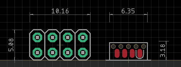
    Some month ago, I stumbled upon SOICbite. It is essentially just a PCB footprint, which is freely available for KiCAD and Eagle. The idea here is to repurpose a conventional SOIC-8 test clip as a programming connector and clip it to the PCB - much like an aligator clip. Those clips are rather cheap, starting at about 2 USD / EUR from China, but most notably, they provide a total of eight contacts in a very small area: compared to a standard 2x4 pin header, the footprint requires about 2.5 times less space!

    mys_soicbize_size_comparison.png

    By the way: you are not restricted to 8 contacts. There are SOIC clips with a higher pin count available as well - you would just have to adjust the SOICbite footprint accordingly.

    Modification: Make it bite

    Unfortunately, it is not possible to use a SOIC-8 clip on the SOICbite footprint without prior modification. The jaws don't close far enough to clamp themselves to the board. To get them to close further, you have to remove some of the plastic in front of the clip's hinge. This is best done with a small, straight needle file. A bit of sandpaper on a scraping card should work as well.

    You need to remove enough material so that the little plastic teeth at the front of the clip can "bite" (hence the name) into the registration holes of the footprint. Keep in mind though: The more material you remove, the closer the opposing contacts get. So close, that they can eventually touch each other and cause a short circuit, if the clip is powered while it is not connected to a PCB.

    mys_soic_side_comparison.jpg

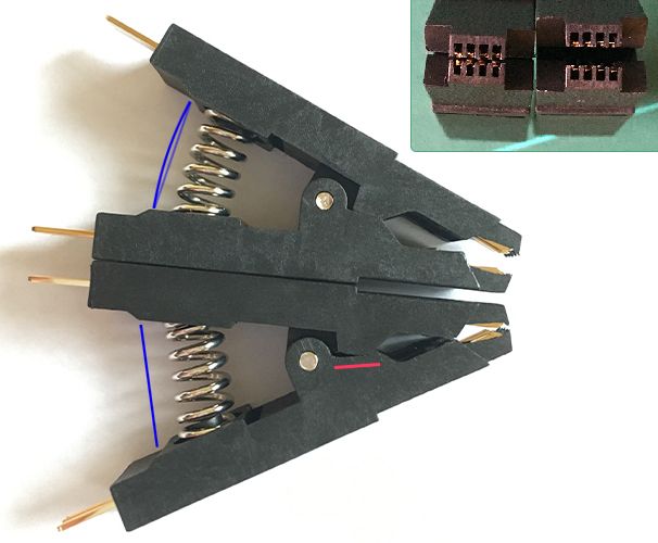
    The picture above shows a stock and modified clip side by side. You can clearly see how much closer the contacts get after modification. The red line marks where the plastic needs to be filed away. The blue lines are added to emphasize how straight the spring of the modified clip is. It is almost completely unloaded and it already has the tiniest amount of backlash. Luckily, the spring is just long enough to make it work with this particular clip.

    Experience: Practical use

    Although there is no real standard for pinouts, the creator of the SOICbite provides suggestions for different use cases:

    Pin UART SPI SWIM SWD ESP8266 USB I2C PIC ICSP
    1 Vcc Vcc Vcc Vcc Vcc Vcc Vcc Vcc
    2 RX2 CS GPIO0 D- Vpp
    3 TX2 GPIO2 D+
    4 GND GND GND GND GND GND GND GND
    5 RX MOSI/MOMI SWIM SWDIO RX SDA DAT
    6 TX MISO SWO TX AUX
    7 CTS SCK/CLK SWCLK CH_PD SCL CLK
    8 RTS RST NRST NRST RST ID

    I'm not following any of these right now and assign the pins as I feel fits best for a certain PCB. This can be a pro or a con, whether you prefer a "foolproof" plug-and-play connection which is always the same, or enjoy the flexibility to adjust it to your needs and simplify routing. But since these clips are so cheap, you could buy a bunch and wire each to a standard-compliant layout for AVRISP, UART, SWD or whatever you need.

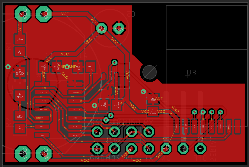
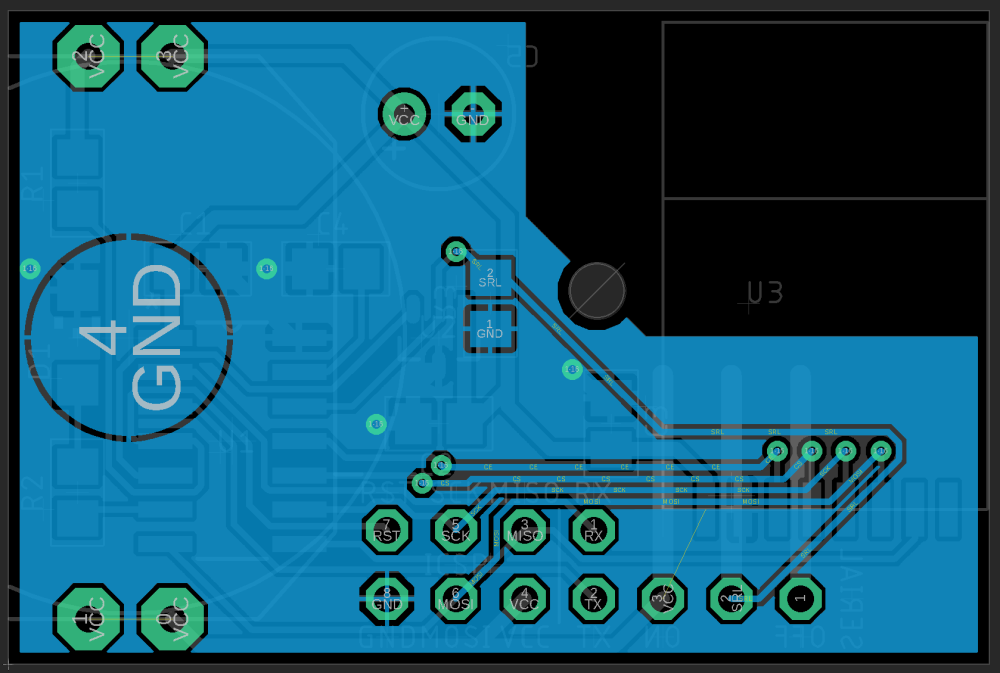
    Routing the traces is obviously a bit more difficult than with a standard pin header, due to the compactness of the footprint and the five registration holes in front of the pads. There's only about 20 mil space between each set of holes. Depending on your DRC settings, the traces may be as thin as 6 mil, but even the cheaper PCB manufacturers should be able to do this properly.

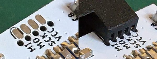
    Anyway - the spring clamps the contact pins onto the PCB and the plastic teeth register in the holes to keep everything aligned. The holes could maybe be the tiniest bit smaller in diameter for a little less play, but it's working great as it is and any smaller drill size could cause problems depending on the manufacturing tolerances, so it's probably best to not fiddle with it.

    mys_soicbite_board.jpg

    I'm using a standard 1.6mm thickness PCBs. While it may also work with 1.2mm boards, I can't really recommend this connector for thinner boards. As I've mentioned above, the spring of the modified clip is almost fully extended and at the very edge of getting loose. To use it on thinner boards and improve the clamping force overall, swapping the spring for a slightly longer one would be advisable.

    For what it is though, the mechanical strength of the connection is rather impressive. The contact pins inside the clip have some spring to them, so they cling onto the pads even if the surface finish is uneven or the clip isn't perfectly perpendicular to the board. It doesn't fall off if you try to pull it out straight, you can move the whole assembly while it is connected and powered - no problem. But you can tilt the PCB out quite easily. I think it is certainly better suited for small and lightweight PCBs, which is fine, because those are typically the kind of boards, where you'd want to use a space-efficient connector on.

    It's definitely not as robust as an interlocking socket-plug type of connector - you honestly can't expect that - but it is certainly on par with a spring-loaded pogo pin jig. So far I've programmed almost a dozen of nodes with it and kept serial connections open for hours while they were sitting on my desk completely unprotected and had no issues.

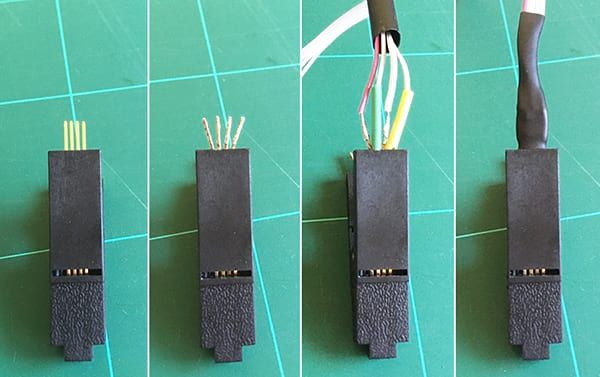
    What I would recommend though, is buying a clip with an already attached wires, because it is a mess to properly solder flexible stranded wires onto the pins - there's only a very tiny gap between them. The following method worked best for me:

    • Fan the pins out by carefully bending them outwards. This provides enough space to solder on regular 30 - 24 AWG stranded wires.
    • Pull on a small diameter piece of shrink tubing over every second wire to avoid shorts later on - using different colors may help to ensure all wires are soldered in the correct order - and solder all four wires.
    • Bend the pins back straight and secure everything with a larger piece of shrink tubing.
    • Repeat the same on the other half of the connector.

    mys_soicbite_wiring.jpg

    Conclusion: Give it a try!

    Is it the best option available for small-scale temporary in-circuit programming and debugging connections? Maybe, maybe not. It works surprisingly well and it can't get much more compact. It is reliable when handled with care, easy to implement into a design, simple to use and doesn't require custom built jigs, which makes it a great, easily accessible choice for hobbyists. It also has the benefit that it doesn't require additional permanently soldered parts on the PCB. And it's dirt cheap.

    The primary downside of the SOICbite is that it needs to be at the PCB edge, which might not always be what you want. Modifying it isn't too troublesome and you can buy already wired clips if you can't be bothered to do it yourself.

    There might be more straight-forward, professional alternatives which are equally space-efficient, like Tag-Connect or pogo pins, but they come with their own downsides. Their spring loaded contacts may were out and fail over time, they need to be pushed down into the PCB manually for the duration of the programming process or require a custom jig to hold it in place. Also, Tag-Connect cables can easily cost 50 USD / EUR.

    I think the SOICbite is a viable option for simple, space-efficient temporary connections and I can totally recommend it for this use-case. I will definitely use it more often in the future.

    TL;DR

    To sum it up, here's a quick rundown of the pro's and con's of the SOICbite connector:

    PROS

    • Very space-efficient (2.5x smaller than a standard 2x4 pin header)
    • Provides a reliable, sufficiently strong connection, comparable to a pogo pin jig, if some caution is exercised
    • Doesn't require any permanently soldered parts on the PCB
    • With prices starting at 2 USD / EUR, SOIC-8 clips are super affordable
    • Higher pin-count SOIC clips are available, if 8 pins aren't enough

    CONS

    • The SOIC-8 clips must be modified to work, but it's easy to do
    • It can only be used at a PCB edge
    • Using thin traces of 5-7 mil width (depending on your design rules) to route between the registration holes might be problematic for some manufacturers
    • It is not really suitable for thin PCBs (< 1.6mm), without replacing the spring

    Where to buy?

    I ordered a bunch of clips from different sellers on AliExpress. They all seem to sell the same model, at least in the lower price ranges. So it should be safe to get the cheapest offer you find.

    Currently, I would recommend this set which comes with an already soldered ribbon cable and two handy little adapters for just 2 USD / 1.80 EUR (plus shipping):
    https://www.aliexpress.com/item/33058340727.html

    This is the model I'm showing in the pictures above. It comes without wires, if you prefer that:
    https://www.aliexpress.com/item/32953869303.html

    This one can be wired up with regular DuPont wires if you prefer that, although it looks a little weak and flimsy:
    https://www.aliexpress.com/item/32908232000.html

    If you don't trust AliExpress or eBay, I'm sure you'll find them at your prefered distributor aswell!

    General Discussion

  • 💬 Battery Powered Sensors
    BearWithBeardB BearWithBeard

    If I remember correctly, writing to the serial port takes about 10s / baud rate for a single byte. That's a little unter 90µs at 115200 baud (common for Arduinos clocking 16 MHz at 5V) or about 1ms at 9600 baud (1MHz for 3V or less).

    Imagine we are transmitting two messages per wake cycle and print another few custom lines to the serial port as well, that may result in about 500 bytes total. This would then add another 45ms on a fast clocking Arduino (115200 baud) or 0.5s (9600 baud) - plus likely some overhead - to the time the microcontroller spends in an active state.

    According to the datasheet (p.312), an ATmega328P clocking at 1MHz consumes about 0.5mA in an active state at about 3V. So, from here on, you could calculate how drastically (or not) an additional ~0.1 - 0.7s of active time per wake cycle would impact the runtime of the battery.

    Since it's possible to run a node for a year or much longer off a set of batteries if it doesn't send lots of messages every few minutes, I doubt you would be able to notice a difference between disabling debug prints or keeping them.

    It is usually much more important to keep the current consumption during the power down phase as low as possible, than shedding off a few ms of active time.

    Announcements battery

  • Novice requesting PCB review and advice for a window / door sensor
    BearWithBeardB BearWithBeard

    It took me a little bit longer to post an update, but I decided to spend some more time with my family and focused on another project for a while. Hope you've all had a good start into the new year!

    I made quite a lot of changes to the PCB and incorporated ideas and suggestions from you guys.

    As always - feel free to skip whatever section you don't care about or just read the headings to get a "tl;dr" version of the changes. :stuck_out_tongue_winking_eye:

    Schematic and PCB layout

    Schematic
    2_1546815815174_windowsensor-atttiny-2-schematic.png
    Top Layer
    1_1546815815174_windowsensor-attiny-2-top.png
    Bottom Layer
    0_1546815815174_windowsensor-attiny-2-bottom.png

    The routing around the Attiny's pins almost looks like I'm working with a single-layer PCB, but I can't use vias except for GND in this area as the coin cell occupies the whole backside (and several (inexpensive) PCB manufactures seem to be unable to make tented vias and cover them with a solder resist mask). I guess those fancy "spirals" around the left-hand pins won't cause any issues.

    Trace width for GND and VCC is still 20 mil. All other signals are now 9 instead of 10mil.

    There are some airwires visible between some of the VCC signals. I guess EAGLE doesn't understand that the four VCC through-hole pads of the battery holder are physically connected. If anyone could tell me how to deal with it, that would be greatly appreciated!

    (And yes, yes. That lonely resistor on the back looks so sad and silly. But it's the position with the shortest routes and least vias I could come up with, so it seems to be the best solution.)

    List of Components

    • U1: Attiny84A-SSU
    • U2: TI DRV5032FB or Honeywell SM353LT
    • U3: NRF24L01+ SMD module
    • R1, R3: 10kΩ (0805)
    • R2: 680Ω (0805)
    • D1: Kingbright 2 mA, 150mcd, 40 deg, red Dome-LED (1206)
    • C1, C2, C3, C4: 0.1µF 50VDC X7R MLCC (0805)
    • C5: 100µF 16VDC electrolytic cap (e.g. Nichicon UMA series)

    I will focus on the Attiny variant for now

    I prefer using the Attiny84 for several reasons over the Atmega328P for this project - it allows to make the overall device a little bit smaller, gives more options for routing signals and costs less than half of an 328P, which feels wasteful to use with most of its pins unconnected.

    I will most likely go back into EAGLE and design a variant for the Atmega328P as well before I'm going to order PCBs the next time so that I get a batch of both anyway - but I don't want to continue working on two variants simultaneously while major changes are likely.

    Ground plane on both PCB layers

    As suggested by @Nca78, I've also added a ground plane on the top layer this time.

    But I'm unsure if this has any consequences for the decoupling capacitors and their corresponding power pins. Doesn't it "break" their current loop? Why would it be considered bad if the plane would be VCC instead? (I definitely need some good reading on this topic.)

    Status LED included

    @Nca78 pointed out that there are SMD LEDs that can produce a bright spotlight with very little power.

    Mouser doesn't seem to have any LED in their catalogue with a current consumption <2mA that's larger than 0402. So the one I chose to include is a 1206 dome-LED from Kingbright which reaches a luminosity of 150mcd at 2mA in a 40° cone. LEDs with similar specs seem to be easily available. I think that should do the job.

    Added serial pins and a jumper

    Originally, I didn't want to add a serial header at all, as it would take up way to much space on the PCB. But @mfalkvidd made me think about a simpler solution: Adding RX/TX pins to the already existing ICSP header.

    This allows for on-demand debugging functionality via software serial if pin 12 is pulled high through the jumper. If the jumper is disconnected, pin 12 will get pulled down to ground and serial functionally will be disabled, going back to normal operation mode and reducing power consumption to a minimum.

    At this point, I don't worry about auto-reset functionality, since the Attiny84 with its 8kB of flash memory hasn't enough space to fit a bootloader besides the actual program.
    That's a consideration to take into account with the Atmega variant.

    Increased distance between antenna and copper

    The new design leaves much more space between the antenna of the NRF24 module and any part of the circuit (at least 5mm). The closest metal part will be a M2 bolt that attaches the board to the enclosure.

    Using an electrolytic capacitor as a buffer instead of a MLCC

    Well ... I went forwards and backwards many times whether to use an electrolytic cap or an MLCC. After all, I concluded using an electrolytic cap is the most sensible solution. Here's my (lengthy) explanation for it:

    • (Large capacity) MLCCs are increasingly difficult to acquire and their prices are going up as well. There is no guarantee that I - or anyone else interested in this project, as private individuals - can get an affordable MLCC in a specific SMD package in a reasonable amount of time. Items that are in stock today can be sold out by tomorrow, with lead times of "53 weeks".

    • The actual capacitance of MLCCs is largely dependent on the applied voltage in relation to its rated voltage (DC bias, some background info). This means that a 100µF MLCC rated for 10VDC might store a charge of only 40 - 70µF when supplied with 3V (average values I've gotten by looking through the online databases from murata and TDK). This would require the use of a MLCC that has a higher nominal capacitance or possibly, depending on the specific part, a higher rated voltage, which has its "sweet spot" at around 3V. But those cost easily 5 - 25 USD / Euro a piece. That's not sensible at all.

    • Last but not least: Reading a paper from a German battery manufacturer ("Leakage current properties of modern electrolytic capacitors"), I concluded that using an electrolytic cap in battery-powered applications might not be as bad as one might think.

      AVX apparently released a paper very similar to this, but unfortunately it doesn’t seem to be (publicly) available anymore. Rubycon writes in a technical note that the specified leakage currents are higher than they actually are, “because it takes too much time to measure the true leakage current”.

      Summarizing, the specified leakage current in a capacitors data sheet is usually far above the actual operating leakage current that should be expected when a voltage is applied to the capacitor continuously. It is generally by a few factors lower than specified, even more so when the supply voltage is far below the rated voltage (TDK, p. 17) - for a 100µF 16VDC cap and a specified leakage current of up to 3µA that is supplied with 3V, the operating leakage current should settle between 100 and 250nA.

      Plus, my experiment with the two prototypes I mentioned in an earlier post seems to back the point that the leakage current of (decent) electrolytic caps isn't a huge deal in low power applications as one might think, since both devices seem to drain the battery equally.

    Considering that 100µF 16VDC electrolytic caps with a total height below 5.5mm are - other than similar MLCCs - rather cheap and widely available, it seems reasonable to stick with an electrolytic cap as a buffer.

    After all, the limiting factor regarding the total uptime of this device isn't the technology of the buffer capacitor - it's the self-imposed constraint in regards to the overall dimensions of the device, thus opting for a tiny CR2032 coin cell. Choosing a slightly larger power source will absolutely have a much bigger impact on the battery life as any kind of capacitor could have.

    Yes, the best possible capacitor might increase the battery life by a few weeks or even two months - a CR2450 instead of a CR2032 would increase it by years.

    For the sake of completeness, there are also specific "low leakage" electrolytic caps available like the UKL series from nichicon which specify a leakage current of less than 0.2µA after two minutes. Unfortunately, with a minimal size of 6.3mm x 11mm they are a bit too large for this project.

    Moved the battery to the back of the PCB

    Making use of the fact that I go back to using a electrolytic cap as a buffer, I can mount the battery as well as the cap to the back of the PCB - as well as the 90° angle pin header for the jumper that otherwise wouldn't fit on the board.

    This makes the device ~2mm thicker (~9mm total thickness) than mounting everything on the top of the PCB (~7mm total thickness) but I can keep the board dimensions of 24mm x 36mm despite adding more components. Having all the thick components on the back also means that the hall effect sensor is as close to the front of the enclosure as possible, reducing the distance to the magnet.

    The CR2032 can easily be replaced by a CR2450, which has a three times higher nominal capacity, without increasing the overall device thickness and only increasing the PCB height from 24mm to 27mm - I just have to commit to using a specific coin cell holder model to adjust the contacts on the PCB accordingly. Until then, I'll stick with the CR2032.


    That's it for now. Your comments, ideas and suggestions are highly appreciated, as always. Thanks for your attention!

    Hardware atmega328p pcb nrf24l01+ pcb layout smd

  • What did you build today (Pictures) ?
    BearWithBeardB BearWithBeard

    @berkseo said in What did you build today (Pictures) ?:

    @monte said in What did you build today (Pictures) ?:

    Or do you mean that they are discontinuing 1.54" displays completely?

    Yes, I mean that these displays are no longer produced. And it is better to focus on new ones.

    Just to clear up a potential misunderstanding: The 1.54" EPDs aren't going to vanish anytime soon. Only the GDEP015OC1 has been discontinued and the GDEH0154D67 may follow, too at some point.

    But Dalian Good Display has just launched the GDEW0154M09 this month, which seems to be the successor of the GDEH0154D67 at first sight. There is also the GDEW0154M10, which supposedly has a better contrast due to a new manufacturing process. Waveshare seems to be still selling their version of the GDEH0154D67, but not any of the new ones.

    I don't think you need to hoard them like other poeple hoard their live-long stock of toilet paper these days. ;)

    General Discussion

  • Something's cooking in the MySensors labs...
    BearWithBeardB BearWithBeard

    @Giovanni-Chiva You need the development branch (2.4.0-alpha) for multitransport. 2.3.2, which you are using, doesn't support that. Download here: https://github.com/mysensors/MySensors/tree/development

    Announcements

  • CR2032 coin cells - expected life?
    BearWithBeardB BearWithBeard

    cr2032-contact.png

    The graph above is from my oldest window contact that is still in service with its first CR2032. It has reported 2902 events in over a year (less than 8 wake cycles per day on average).

    cr2032-temp.png

    The second graph is from my oldest temperature & humidity node, also running off a CR2032. Since march 2020, it reported 180k data points (temp & hum every 5 minutes).

    Unfortunately I didn't configure them to report the battery voltage back then, but I took a reading with my DMM right now: The window node reads 3.041V and the temperature node 2.993V. What I'm trying to show is that nodes can run for years with a CR2032.

    The temperature node should be the most discharged CR2032 I have in use currently, so I have yet to find out at which voltage they stop working. But I think 2.8V should still be fine if you have enough capacity to counteract the voltage drop during transmission.

    If the battery in your node died suddenly, I guess the node may have failed to sleep for some reason. I had this issue before a couple of times and I can only assume that the node lost connection to the repeater and drained the whole battery in a find-parent-loop.

    Update (mid of Nov 21): The temperature & humidity node died a few days ago. It sent roughly 350k individual sensor readings over a span of 20 months. That's about the maximum lifetime I could expect with 12 wake cycles per hour.

    Hardware

  • Is this the end of nrf24l01?
    BearWithBeardB BearWithBeard

    IIRC, they are not recommended for new designs for at least a few years now. But you can still buy plenty of NRF24L01 ICs from Mouser or LCSC as of today.

    CDEbyte still stocks various modules with NRF24 in their stores (see CDSENET, Cojxu and CDEBYTE - they all belong to the same company), but it seems like they are gradually drifting towards replacing it with the SI24R1 IC which are then labeled as the E01C series, as opposed to E01 for the NRF24. I don't own any of the E01C modules, but I'd assume that they still work better than the average unspecified Chinese NRF24 clone from eBay.

    What would you recommend for new projects?

    NRF5 maybe? They are fully fledged ARM-based SoCs with the NRF24-compatible transceiver included, but note that they are more difficult to work with than the good old Arduino + NRF24 combo. You'll need a compatible programmer, may need additional programming knowledge and I don't know if there are any through hole modules with pins available.

    Look for the E73 series from CDEbyte. At least the NRF52832 is rather well supported by MySensors.

    There are a couple of threads in the forum to get you going with NRF5, like the NRF5 beginners guide or the NRF5 platform overview. I also wrote a short guide how I got my first E73 to work using an STM32 as a Black Magic Probe.

    If you're looking for replacement transceivers to use with ATmegas, look for RFM69 / RFM9x (LoRa). They have a potentially much higher range than NRF24 due to the lower radio frequencies they use, but need a little more effort to set up, notably because you have to manually solder an antenna to them.

    I designed an infographic about the commonly used RFM modules by HopeRF a while ago if you need an overview.

    General Discussion nrf24 nrf24l01+ radio

  • Battery life calculator
    BearWithBeardB BearWithBeard

    @DenisJ With 120 wakeups per hour as per your calculator screenshot, you'd wake up every 30 seconds instead of once every 2 minutes. ;)

    You should easily be able to get more than a year of runtime with that hardware setup and the mentioned thresholds for temp/hum.

    Hardware

  • Security vulnerabilities in Home Assistant & custom integrations
    BearWithBeardB BearWithBeard

    I know that some folks in here are using Home Assistant, but they may not all be visiting the HA website regularly. So I thought I'd share this info here.

    They have published two security disclosures recently, informing us about security vulnerabilities found in third party integrations (including HACS, commonly used to integrate Alexa and such), which allowed an attacker to access any file that is accessible by the Home Assistant process. Be sure to upgrade to Home Assistant Core 2021.1.5 or later and all custom integrations as soon as possible.

    More details as well as (all?) affected custom integrations can be found in the Home Assistant blog.

    Home Assistant home-assistant security

  • Unable to initialize NRF24L01+ when using an ATmega328P-PU
    BearWithBeardB BearWithBeard

    Oh shhhhoot.

    So by switching from 328p8m to nanoatmega328p in order to fix some issues, I actually made it worse, because the latter sets F_CPU to 16000000L.

    What an unbelievable oversight on my part. That explains why I had to monitor the serial output at 1/16th of the baud rate.

    Overwriting the frequency in the config file with board_build.f_cpu = 8000000L did the trick. No need to adjust the SPI bus speed anymore. Baud rate set to 57600, monitoring at 7200 (1/8th, CKDIV8 enabled). All good!

    Thanks for pointing that out, @tekka! I feel embarrassed, that I didn't notice that myself.


    Small update -- after some more testing, setting board_build.f_cpu = 1000000L and #define MY_BAUD_RATE 9600 seems to be even better with CKDIV8 enabled. 1ms is actually 1ms and communication between nodes is way more responsive.

    Powering the sensor node on, initializing, finding parent, presentation, etc,.. is now done withing 6 seconds instead of roughly 30 seconds.

    Troubleshooting

  • Something's cooking in the MySensors labs...
    BearWithBeardB BearWithBeard

    Well this is just brilliant! And the timing couldn't be any better, as I was just about to conquer our garden with an army of RFM69 nodes. :D

    For the last three days I was sending an incrementing number every five minutes with each an NRF24 and RFM69 node to a 3.3V Pro Mini MQTT gateway (W5500) without issues. Today I decided to flick the switch and route my existing NRF24 network through it, effectively replacing my trusty ESP MQTT gateway (which I will keep as a backup, just in case) and it's looking good.

    RAM:   [=======   ]  74.7% (used 1530 bytes from 2048 bytes)
    Flash: [========  ]  84.5% (used 25972 bytes from 30720 bytes)
    

    Here's my basic sketch in case anyone might find it useful:

    #include <Arduino.h>
    
    #define MY_BAUD_RATE 9600
    #define MY_DEBUG
    
    #define SKETCH_NAME "Multi-TP Gateway"
    #define SKETCH_VERSION "1.1"
    
    // Ethernet & MQTT config
    #define MY_GATEWAY_MQTT_CLIENT
    #define MY_MQTT_CLIENT_ID "mys-gw"
    #define MY_MQTT_PUBLISH_TOPIC_PREFIX "mys-out"
    #define MY_MQTT_SUBSCRIBE_TOPIC_PREFIX "mys-in"
    
    #define MY_MQTT_USER "username"
    #define MY_MQTT_PASSWORD "password"
    
    #define MY_IP_ADDRESS 192, 168, 178, 215 
    
    #define MY_CONTROLLER_IP_ADDRESS 192, 168, 178, 220
    #define MY_PORT 1883
    
    // SoftSPI for radios
    #define MY_SOFTSPI
    #define MY_SOFT_SPI_SCK_PIN 14 // A0
    #define MY_SOFT_SPI_MOSI_PIN 15 // A1
    #define MY_SOFT_SPI_MISO_PIN 16 // A2
    
    // NRF config
    #define MY_RADIO_RF24
    #define MY_RF24_CHANNEL 83
    #define MY_RF24_PA_LEVEL RF24_PA_HIGH
    #define MY_RF24_USE_INTERRUPTS
    #define MY_RF24_IRQ_PIN 3
    #define MY_RF24_CE_PIN 7
    #define MY_RF24_CS_PIN 8
    
    // RFM config
    #define MY_RADIO_RFM69
    #define MY_RFM69_NEW_DRIVER
    #define MY_RFM69_NETWORKID 69
    #define MY_RFM69_FREQUENCY RFM69_868MHZ
    #define MY_IS_RFM69HW
    #define MY_RFM69_IRQ_PIN 2
    #define MY_RFM69_CS_PIN 9
    
    // https://github.com/Wiznet/WIZ_Ethernet_Library
    #include <Ethernet.h> 
    
    #include <MySensors.h>
    
    void presentation()
    {
    	sendSketchInfo(SKETCH_NAME, SKETCH_VERSION);
    }
    
    void setup()
    {
    }
    
    void loop()
    {
    }
    
    Announcements

  • Ebyte nRF24 module comparison (2020)
    BearWithBeardB BearWithBeard

    @NeverDie @waspie
    I just found them on cdebytes eBay store for 10.87USD for ten units (1.08USD each) with free shipping. They are currently on sale with 20% off.

    Also, LCSC sells them for 1.38USD a piece, but they only have 5 units at stock right now.

    Hardware
  • Login

  • Don't have an account? Register

  • Login or register to search.
  • First post
    Last post
0
  • MySensors
  • OpenHardware.io
  • Categories
  • Recent
  • Tags
  • Popular