@Joost Perhaps you started the node at some point during development without presenting the sensors? If HA has already seen your node before, I think it will not update its children/sensors again even if you restart and have the node send the presentation again. What I do when this happens is to shut down HA, remove the entry from the json file and restart HA again. Then restart the node so it presents itself again.
Posts made by maghac
-
RE: (Solved) S_Multimeter in HomeAssistant
-
RE: What did you build today (Pictures) ?
@Nca78 You're probably correct. I first wanted to keep the sensor "dumb" and put all logic in the controller, but it makes sense that the sensor actually returns the true alarm state - which is ON if the LED is blinking.
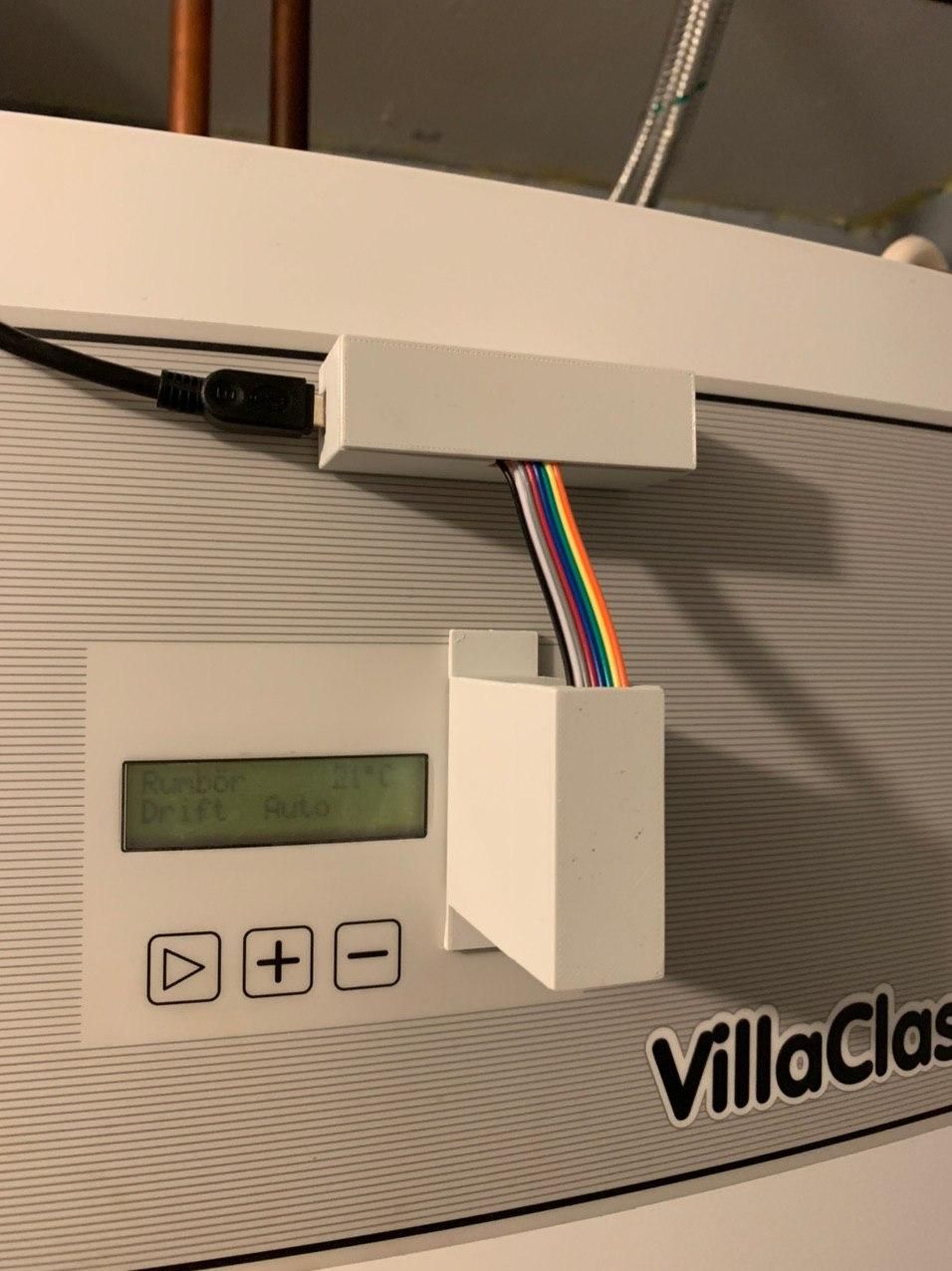
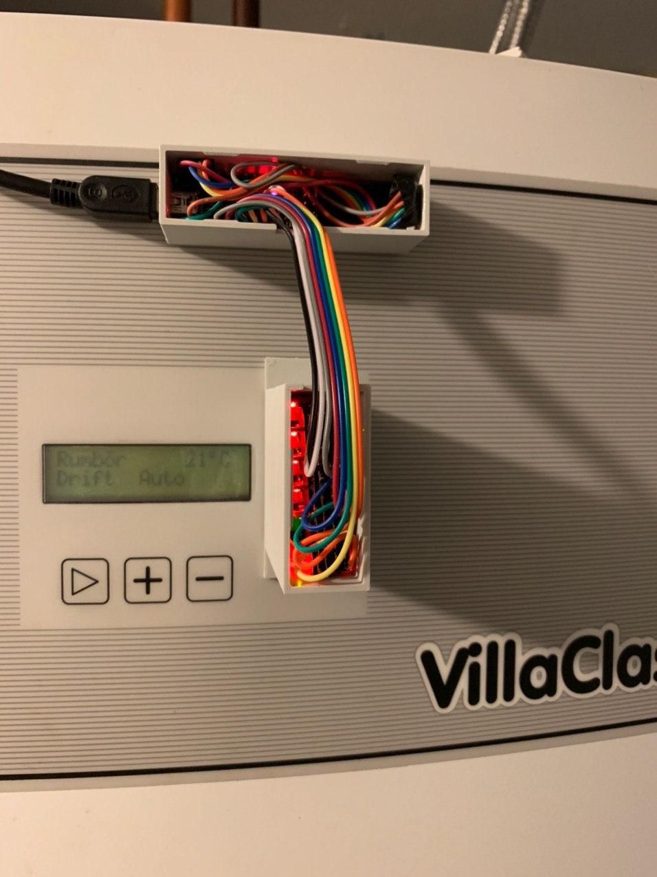
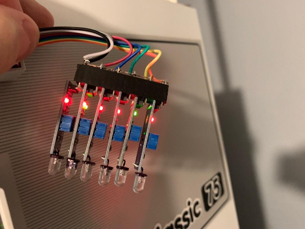
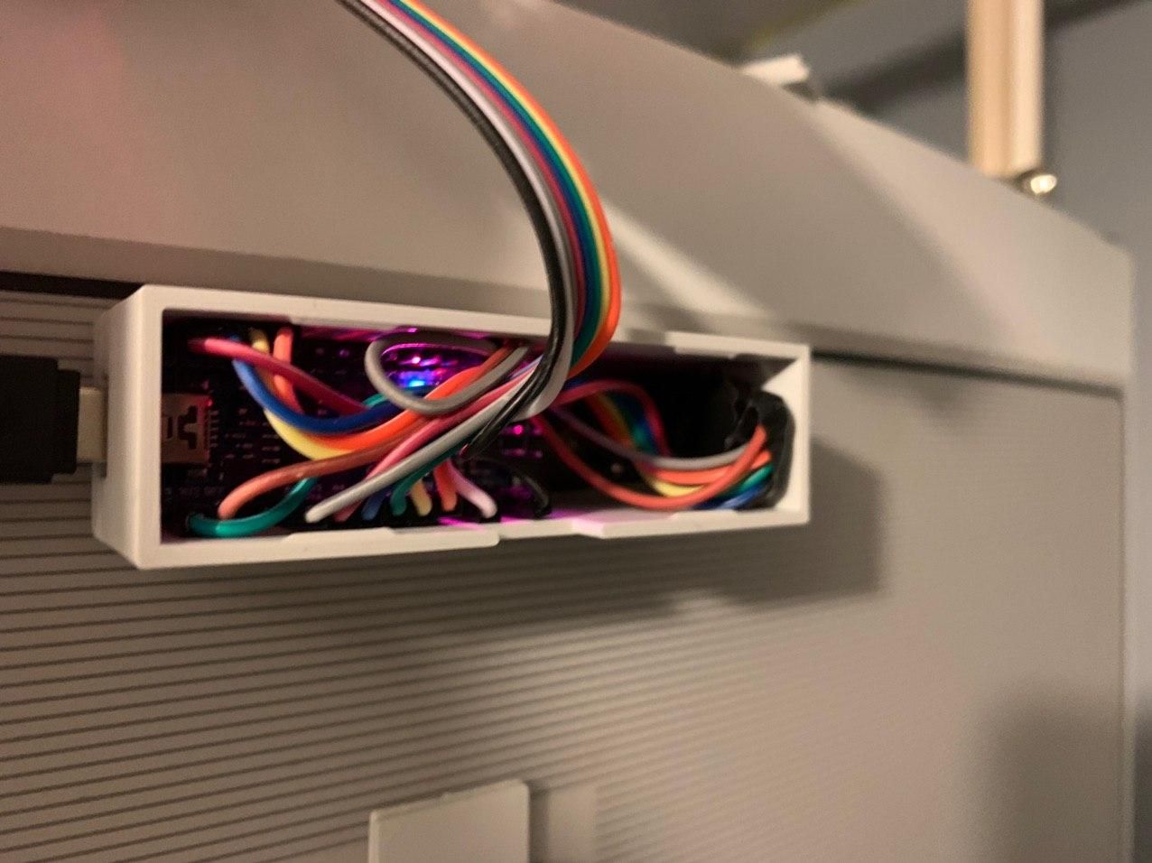
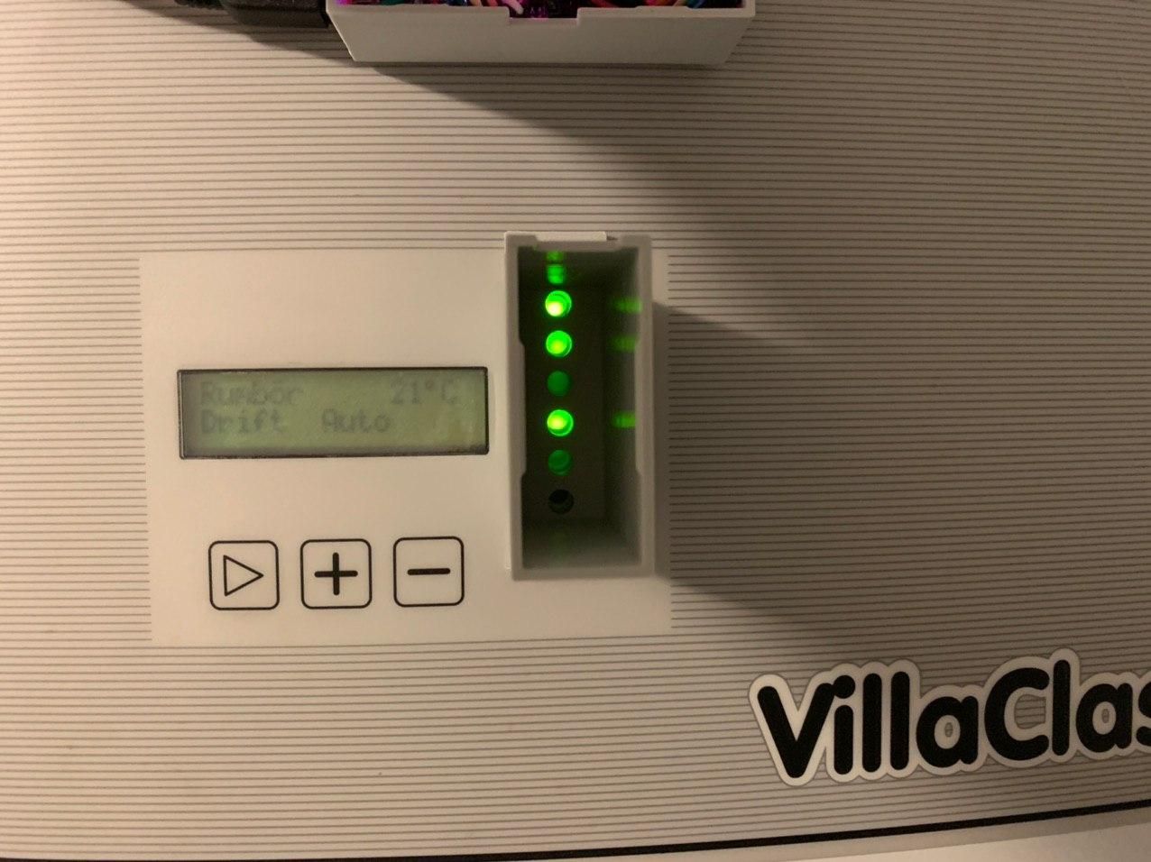
-
RE: What did you build today (Pictures) ?
Built a heat pump monitor based on mysensors on an Nano board and a few LM393 light sensors.
It's simply reading the status LEDs and tells me if they're on or off, and it means I can correlate e.g the compressor or circulation pumps with the electricity usage read from the power meter.
Also, which actually was the main driver behind the project, it allows me to send an alarm to my phone in case the alarm LED goes on. This is usually caused by incorrect pressure somewhere in the system and can be fixed by simply restarting the system. When the alarm triggers, it shuts down everything which is a bit annoying since it can take a few hours before I notice it (usually not until I go in the shower and there is no hot water). I now have to figure out how to deal with the fact that the alarm LED is blinking, which causes a stream of "alarm ON, alarm OFF, alarm ON, ... ." etc messages in Telegram There should be a way to fix this in Home Assistant I hope.
An interesting thing was that I was not able to tune the sensors to give me an accurate on/off digital signal. I therefore have to read the analog signal, and in the sketch decide whether it's on or off depending on the value. The values are in the 0..1023 range and the threshold was somewhere around 1000, so I think it was too close to the end of the range for the adjustment potentiometer.
-
RE: RGB LED strip
Hi,
yes, W is just another channel and it works the same way as the RGB channels. There is one single on/off and dimmer amount for all 4 channels. In Home Assistant this works as expected - there is one single unit which has a color selector for RGB values and a slider for the W value.Not sure why Domoticz shows it as two separate units - perhaps you can check if there is an option to modify this behaviour?
-
RE: [SOLVED] NRF24 can not sleep
@mfalkvidd How do you measure such low currents? I have the problems with some nodes that are consuming way too much power and I'd like to check them.
-
RE: What did you build today (Pictures) ?
@mfalkvidd said in What did you build today (Pictures) ?:
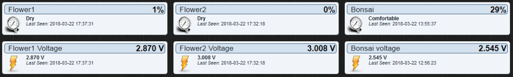
Today I finally got my thumbs out and upgraded my plant monitoring to MySensors 2.x (from 1.x).
Updated sketch is available on Github: https://github.com/mfalkvidd/arduino-plantmoistureResult: I really need to water my plants But the 2.5 year old batteries are still going strong.
What kind of components is this running on? I am having trouble getting my batteries to run even 2.5 months (or 2.5 weeks for the outside temp sensor...)
-
RE: RGB LED strip
@dmonty said in RGB LED strip:
Just finished a similar project using WS2812B.
- MySensors/Domoticz support.
- Infrared Remote support (common 44 key color picker)
- Color change & fade animations ++.
Cool. I've played with WS2812B and FastLed in another project. But I'm not sure if they are good enough for general illumination though?
-
RE: RGB LED strip
@bgunnarb said in RGB LED strip:
@maghac I have implemented your 1.8 and I am impressed with the good structure and the performance of your code! Kudos!
Thanks! Let me know if you have any problems with it - I am still facing some issues actually. After some time (a couple of days or so), the LED strip does not respond to on/off commands any longer. I've implemented a debug feature to try to diagnose the cause of it (I send the node a V_TEXT message and it responds with a series of V_TEXT messages containing the values of variables).
-
RE: MySensors 2.2.0 released
Hi,
I've noticed that since the upgrade to 2.2.0 my nodes are now sending some new internal messages every now and then. I'm using a MQTT gateway and sometimes I see these messages coming through:mysensors-out/1/255/3/0/33 600000
mysensors-out/1/255/3/0/32 500What are internal messages types 32 and 33? Can't find them in the list on https://www.mysensors.org/download/serial_api_20#internal
-
RE: π¬ Connecting the Radio
@gohan But then I would need additional hardware to use DualOptiBoot?
Anyone have any quick instructions on how to build a new custom version of MySensorsBootLoader using MY_RF24_CE_PIN = 8
I have access to ArduinoIDE on Windows or a Ubuntu 16.04 box.
-
RE: π¬ Connecting the Radio
@mfalkvidd Maybe I'll give that a try.
I think FOTA will fail as the bootloader will try to initialise the radio with the default pin, right? Then I'll need software pwm or recompile my own bootloader.
-
RE: RGB LED strip
Well, it took some time, but here is v1.8 at last!
I have modified the code to handle RGBW strips, since I realized that the white light from RGB strips is very uncomfortable and not really suitable for general illumination. It should be fairly easy to convert it back to RGB though. Adding the W channel means that I now need 4 PWM pins, and therefore it was necessary to redefine one of the pins that the radio is connected to - the sketch now expects CE to be connected to pin 8 instead of 9 which is the default (a pro mini only has 3 free PWM pins if you use the default setup).
I've also completely changed now programs/modes are implemented so it should be easier to add new programs. Feel free to experiment with this and let me know what you think.
/** * This program is free software; you can redistribute it and/or * modify it under the terms of the GNU General Public License * version 2 as published by the Free Software Foundation. * * LED STRIP sketch for Mysensors ******************************* * * REVISION HISTORY * 1.0 * Based on the example sketch in mysensors * 1.1 * prgspeed parameter (send as V_VAR1 message) * HomeAssistant compatible (send status to ack) * 1.2 * OTA support * 1.3 * Power-on self test * 1.4 * Bug fix * 1.5 * Other default values * 1.6 * Repeater feature * 1.7 * Multitasking. Alarm and RELAX modes. * 1.8 * Reengineered programs/modes logic. * RGBW variant. Requires 4 PWM pins, so we need to move use a different pin for one of radio connections. */ #define MY_OTA_FIRMWARE_FEATURE // #define MY_REPEATER_FEATURE #define MY_NODE_ID AUTO #define MY_RADIO_NRF24 //#define MY_DEBUG // Normally the radio uses pin 9 for CE #define MY_RF24_CE_PIN 8 #include <MySensors.h> #define CHILD_ID_LIGHT 1 #define SN "LED Strip" #define SV "1.8" MyMessage lightMsg(CHILD_ID_LIGHT, V_LIGHT); MyMessage rgbwMsg(CHILD_ID_LIGHT, V_RGBW); MyMessage dimmerMsg(CHILD_ID_LIGHT, V_DIMMER); MyMessage prgspeedMsg(CHILD_ID_LIGHT, V_VAR1); MyMessage programMsg(CHILD_ID_LIGHT, V_VAR2); #define RR 0 #define GG 1 #define BB 2 #define WW 3 byte current[] = {255, 255, 255, 255}; byte target[] = {255, 255, 255, 255}; byte save[] = {0, 0, 0, 0}; byte temp[] = {0, 0, 0, 0}; float delta[] = {0.0, 0.0, 0.0, 0.0}; char rgbwstring[] = "000000ff"; int on_off_status = 0; int dimmerlevel = 100; int prgspeed = 20; unsigned long last_update = 0; unsigned long tick_length = 5; int fade_step = 0; int program_timer; int program_cycle; int program_step; // Make sure these are PWM pins #define REDPIN 6 #define GREENPIN 5 #define BLUEPIN 3 #define WHITEPIN 9 #define LIGHT_NORMAL 0 #define LIGHT_FADING 1 #define PROGRAM_NOP 0 int light_mode = LIGHT_NORMAL; int program_mode = PROGRAM_NOP; #define SET 0 #define SET_AND_WAIT 1 #define SET_RANDOM 2 #define SET_RANDOM_AND_WAIT 3 #define FADE 4 #define FADE_RANDOM 5 #define WAIT 6 typedef struct rgb_cmd { byte cmd; int p; byte rgbw[4]; } rgb_cmd; rgb_cmd program_ALARM[] = { {SET_AND_WAIT, 25, {255, 255, 255, 0}}, {SET_AND_WAIT, 25, {0, 0, 0, 0}}, {SET_AND_WAIT, 25, {0, 0, 0, 255}}, {SET_AND_WAIT, 25, {0, 0, 0, 0}} }; rgb_cmd program_RELAX[] = { {FADE, 1000, {255, 32, 0, 0}}, {FADE, 1000, {255, 32, 16, 0}}, {FADE, 1000, {255, 16, 32, 0}}, {FADE, 1000, {255, 128, 0, 0}}, {FADE, 1000, {255, 32, 0, 0}}, {FADE, 1000, {255, 32, 32, 0}}, {FADE, 1000, {255, 0, 32, 0}} }; rgb_cmd program_PARTY[] = { {SET_AND_WAIT, 10, {255, 0, 0, 0}}, {SET_AND_WAIT, 10, {0, 0, 0, 255}}, {SET_AND_WAIT, 10, {255, 0, 0, 0}}, {SET_AND_WAIT, 10, {0, 0, 0, 255}}, {SET_AND_WAIT, 10, {255, 0, 0,0}}, {SET_AND_WAIT, 10, {0, 0, 0, 255}}, {SET_AND_WAIT, 10, {255, 0, 0,0}}, {SET_AND_WAIT, 10, {0, 0, 0, 255}}, {SET_AND_WAIT, 10, {255, 0, 0, 0}}, {SET_AND_WAIT, 10, {0, 0, 0, 255}}, {FADE_RANDOM, 50, {255, 255, 255, 0}}, {FADE_RANDOM, 50, {255, 255, 255, 0}}, {FADE_RANDOM, 50, {255, 255, 255, 0}}, {FADE_RANDOM, 50, {255, 255, 255, 0}}, {SET_AND_WAIT, 50, {0, 0, 255, 0}}, {SET_AND_WAIT, 50, {0, 255, 255 ,0}}, {SET_AND_WAIT, 50, {255, 255, 0, 0}}, {SET_AND_WAIT, 50, {0, 255, 0, 0}}, {FADE_RANDOM, 50, {255, 255, 255, 0}}, {FADE_RANDOM, 50, {255, 255, 255, 0}}, {FADE_RANDOM, 50, {255, 255, 255, 0}}, {FADE_RANDOM, 50, {255, 255, 255, 0}}, {FADE_RANDOM, 50, {255, 255, 255, 0}} }; rgb_cmd* programs[] = { &program_ALARM[0], &program_RELAX[0], &program_PARTY[0] }; const int program_steps[] = { sizeof(program_ALARM)/sizeof(rgb_cmd), 7, 22 }; void setup() { // Fix the PWM timer. Without this the LEDs will flicker. TCCR0A = _BV(COM0A1) | _BV(COM0B1) | _BV(WGM00); // Output pins pinMode(REDPIN, OUTPUT); pinMode(GREENPIN, OUTPUT); pinMode(BLUEPIN, OUTPUT); pinMode(WHITEPIN, OUTPUT); } void presentation() { // Send the Sketch Version Information to the Gateway sendSketchInfo(SN, SV); present(CHILD_ID_LIGHT, S_RGBW_LIGHT); } void selftest() { on_off_status = 1; current[RR] = 255; current[GG] = 0; current[BB] = 0; current[WW] = 0; set_hw_status(); wait(200); current[RR] = 0; current[GG] = 255; set_hw_status(); wait(200); current[GG] = 0; current[BB] = 255; set_hw_status(); wait(200); current[BB] = 0; current[WW] = 255; set_hw_status(); wait(200); current[RR] = 0; current[GG] = 0; current[BB] = 0; set_hw_status(); wait(200); on_off_status = 0; } void loop() { static bool first_message_sent = false; if ( first_message_sent == false ) { selftest(); set_hw_status(); send(rgbwMsg.set(rgbwstring)); send(lightMsg.set(on_off_status)); send(dimmerMsg.set(dimmerlevel)); send(prgspeedMsg.set(prgspeed)); send(programMsg.set(program_mode)); first_message_sent = true; } unsigned long now = millis(); // Maybe we wrapped around? Then reset last_update to 0. if (now < last_update) { last_update = 0; } if (now - last_update > tick_length) { last_update = now; // If we're fading, finish that before we do anything else if (light_mode == LIGHT_FADING) { calc_fade(); } else { if (program_mode > PROGRAM_NOP) { handle_program(); } } } set_hw_status(); } void receive(const MyMessage &message) { int val; if (message.type == V_RGBW) { for (int i=0; i<=3; i++) { temp[i] = hextoint(message.data[i*2]) * 16 + hextoint(message.data[i*2+1]); } // Save old value strcpy(rgbwstring, message.data); init_fade(prgspeed, temp); send(rgbwMsg.set(rgbwstring)); } else if (message.type == V_LIGHT || message.type == V_STATUS) { val = atoi(message.data); if (val == 0 or val == 1) { on_off_status = val; send(lightMsg.set(on_off_status)); } } else if (message.type == V_PERCENTAGE) { val = atoi(message.data); if (val >= 0 and val <=100) { dimmerlevel = val; send(dimmerMsg.set(dimmerlevel)); } } else if (message.type == V_VAR1 ) { val = atoi(message.data); if (val >= 0 and val <= 2000) { prgspeed = val; send(prgspeedMsg.set(val)); } } else if (message.type == V_VAR2 ) { val = atoi(message.data); if (val == PROGRAM_NOP) { stop_program(); send(programMsg.set(val)); } else { init_program(val); send(programMsg.set(val)); } } else { return; } } void execute_step(rgb_cmd cmd) { if (cmd.cmd == SET) { set_rgb(cmd.rgbw); } else if (cmd.cmd == SET_AND_WAIT) { set_rgb(cmd.rgbw); program_timer = cmd.p; } else if (cmd.cmd == SET_RANDOM) { set_rgb_random(cmd.rgbw); } else if (cmd.cmd == SET_RANDOM_AND_WAIT) { set_rgb_random(cmd.rgbw); program_timer = cmd.p; } else if (cmd.cmd == FADE) { init_fade(cmd.p, cmd.rgbw); } else if (cmd.cmd == FADE_RANDOM) { init_fade_random(cmd.p, cmd.rgbw); } else if (cmd.cmd == WAIT) { program_timer = cmd.p; } } void init_program(int program) { program_mode = program; program_step = 0; program_timer = 0; save_state(); execute_step(programs[program_mode-1][0]); } void handle_program() { if (program_timer > 0) { program_timer--; } if (program_timer == 0) { program_step++; if (program_step == program_steps[program_mode-1]) { program_step = 0; } execute_step(programs[program_mode-1][program_step]); } } void stop_program() { restore_state(); light_mode = LIGHT_NORMAL; program_mode = PROGRAM_NOP; } void save_state() { memcpy(save, current, 4 ); } void restore_state() { memcpy(current, save, 4 ); } void set_rgb (byte rgbw[]) { light_mode = LIGHT_NORMAL; memcpy(current, rgbw, 4); } void set_rgb_random (byte rgbw[]) { light_mode = LIGHT_NORMAL; for (int i=0; i <= 3; i++){ current[i] = random(rgbw[i]); } } void init_fade(int t, byte rgbw[]) { light_mode = LIGHT_FADING; fade_step = t; memcpy(target, rgbw, 4); for (int i=0; i<=3; i++) { delta[i] = (target[i] - current[i]) / float(fade_step); } } void init_fade_random(int t, byte rgbw[]) { light_mode = LIGHT_FADING; fade_step = t; for (int i=0; i<=3; i++) { target[i] = random(rgbw[i]); delta[i] = (target[i] - current[i]) / float(fade_step); } } void calc_fade() { if (fade_step > 0) { fade_step--; for (int i=0; i<=3; i++) { current[i] = target[i] - delta[i] * fade_step; } } else { light_mode = LIGHT_NORMAL; } } void set_hw_status() { analogWrite(REDPIN, on_off_status * (int)(current[RR] * dimmerlevel/100.0)); analogWrite(GREENPIN, on_off_status * (int)(current[GG] * dimmerlevel/100.0)); analogWrite(BLUEPIN, on_off_status * (int)(current[BB] * dimmerlevel/100.0)); analogWrite(WHITEPIN, on_off_status * (int)(current[WW] * dimmerlevel/100.0)); } byte hextoint (byte c) { if ((c >= '0') && (c <= '9')) return c - '0'; if ((c >= 'A') && (c <= 'F')) return c - 'A' + 10; if ((c >= 'a') && (c <= 'f')) return c - 'a' + 10; return 0; }
-
RE: π¬ Connecting the Radio
Thanks - I use NRF24 radios.
I found MY_RF24_CE_PIN which I redefined to pin 8 which worked absolutely fine.
The problem I have now is that now cannot use the Newbie PCB anymore
-
RE: π¬ Connecting the Radio
Is it possible to change any of the radio pins 9, 10, 11 to something else? The reason is that I'd like to use 4 PWM pins and currently I only have pins 3,5,6 available on my Pro Mini.
-
RE: What did you build today (Pictures) ?
@gohan said in What did you build today (Pictures) ?:
I have seen a video where you can convert your pictures and print them using a 3D printer
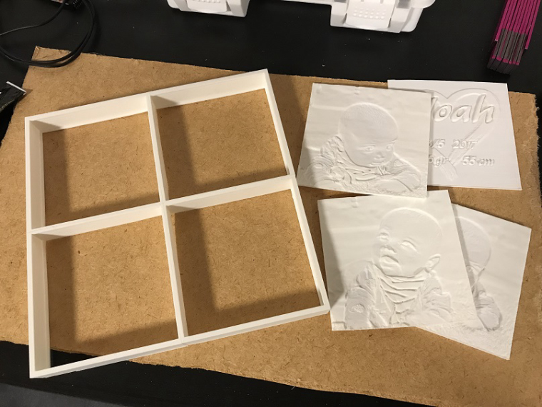
Correct, these are 3D printed lithophanes (https://en.wikipedia.org/wiki/Lithophane). I used http://3dp.rocks/lithophane/ to convert jpg files to STL files for printing.
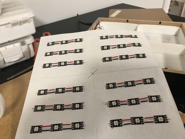
-
RE: What did you build today (Pictures) ?
I built a lithophane lamp for my grandson. The electronics is basically only a pro mini and 36 neopixels. Sadly this version is not mysensorized but maybe I'll do that in version 2
-
RE: mysensors.json file structure
@archiijs I use the NppFTP plugin, it supports both ftp and sftp.
-
RE: mysensors.json file structure
@sindrome73 It's not used unless you use Home Assistant as a controller for mysensors.
@Richard-van-der-Plas It's a JSON file, so you can use any editor that understands json to edit it. No need to use nano or vi.
I personally use notepad++ to remote edit files on my server, it has a nice json plugin to pretty print json files. You could also use an online editor, e.g https://jsonformatter.org/ or something.
-
RE: π¬ Advanced Gateway Options
@Strixx Sorry, I don't remember and I have since then stopped using the LEDs. Couldn't get the inverse feature to work and I realized having LED indicators were not all that useful anyway in the end. If the gateway works, I will see it on MQTT traffic anyway.
-
RE: RGB LED strip
@moskovskiy82 I'll see if I'll have time to work on it this week, I'll post an update when I have something.
-
RE: RGB LED strip
@moskovskiy82 said in RGB LED strip:
And it worked. Except that fading/RELAX don't work out for me. Instead just get a flashing of white light. So i thought you might know some other parts must be adjusted as my arduino knowledge is not there yer
That's the alarm program you are seeing. Perhaps it doesn't decode the incoming messages properly - I'll have to take a second look at the code.
-
RE: RGB LED strip
@bgunnarb Thanks. As program space is limited, I chose not to put too much effort in input data validation, instead relying on the controller to not submit incorrect values. Maybe a quick range check would not waste so many bytes though.
Right now I am however experiencing some strange behavior - I can turn the the lamp on and off and I can dim it, but I cannot change the color of the strip. Also, the RELAX program does not work but the ALARM program works fine. So there are some other bugs that need to be ironed out
-
RE: RGB LED strip
@xypzo said in RGB LED strip:
@maghac said in RGB LED strip:
your connections, perhaps you're connecting to the wrong pin on the arduino
Then green keeps on, so it should be a pin 6 problem, but i can't find it. Maybe I try a 10kohm resistor between gate and ground... Or IRFZ instead of IRLZ transistors.
BTW, bought a LD362A ufo which works great with my controller, but i still want to win this battle!
You could try to use a different pin. Can't remember off the top of my head which pins are PWM capable though.
I've had a couple of cheap arduino clones where some of the pins were not correctly soldered.
-
RE: How to send MQTT message from controller to Node?
@siod Your mysensors gateway will handle this for you (assuming you have a MQTT gw, which I think you do since you can receive data from your mysensors nodes).
Just send the correct MQTT message and the gateway will route it to the node. You then need to handle the message in the receive() function in your sketch.
Have a look at https://forum.mysensors.org/topic/6765/rgb-led-strip, where I describe how I built my RGB lamp. It both sends and receives messages.
-
RE: π¬ Motion Sensor
@siod said in Motion Sensor:
a
You have a HC-SR501 sensor? I had that same question before and then I realized that the HC-SR501 actually has a 3.3 V regulator and if you bypass it you can run it on 3.3V.
-
RE: RGB LED strip
@xypzo Double check your connections, perhaps you're connecting to the wrong pin on the arduino? If you swap red and green, what happens then?
-
RE: RGB LED strip
@mick said in RGB LED strip:
@maghac Thanks for the reply, mate. The light looks great mounted up - very impressed!
Thanks! The "relax" program is actually quite nice since it changes colours so slowly so it takes a while before you notice it. A great way to impress your dinner guests
-
RE: RGB LED strip
@mick No, I have a separate 12V cable and a transformer from a regular wall outlet.
-
RE: RGB LED strip
@DrJeff That's the Newbie PCB by @sundberg84 (https://www.mysensors.org/hardware/newbie-pcb)
-
RE: RGB LED strip
Yes, after googling it I could see it was related to setting the timers. There is maybe another way to fix it and still keep the correct timer functions for other functionalities to be intact (e.g so that @moskovskiy82 can still use the DHT22), but I haven't investigated further. In any case, I believe it's easier to split separate functions to separate physical units instead of trying to put as much functionality into one single unit as possible.
In my case, the unit is mounted in a not-so-well-ventilated enclosure in the ceiling, so I doubt that I would get a correct temperature reading anyway
-
RE: RGB LED strip
@moskovskiy82 Thanks!
To be absolutely honest I'm not exactly sure what the TCCR0A statement does I had problems with flickering LEDs so I googled it and someone on the arduino.cc forums had the same problem and fixed it by putting that line in the code.
Using other pins for the LEDs should be fine, as long as they are PWM pins of course. Just change the #define statements accordingly.
-
RE: RGB LED strip
@OliverDog HA will not send VAR1 or VAR2 unless you implement some specific functionality to do this. I set up switches in HA to send the correct MQTT message to the mysensors gateway in order to activate the alarm and relax modes. Here's my switch.yaml file:
- platform: tellstick - platform: mqtt name: "Alarm" command_topic: "mysensors-in/3/1/1/0/25" payload_on: "1" payload_off: "0" optimistic: false qos: 0 retain: false - platform: mqtt name: "Relax" command_topic: "mysensors-in/3/1/1/0/25" payload_on: "2" payload_off: "0" optimistic: false qos: 0 retain: false
-
RE: RGB LED strip
@OliverDog, thanks!
The V_VAR1 message is used to set the speed of the fading (e.g the time between stepping the RGB values towards the value received with the V_RGB message). Not sure why it doesn't work for you, but maybe it's related to the fact that you don't have the real RGB leds?
You may be interested to know that I have implemented a new version of this sketch. The problem with the old one is that it did the fading in a loop which meant that no new commands were processed during the fade. The new version implements it differently so that messages can be received while the light is fading in a sort of multitasking fashion. This opened up the possibility to implement "programs" that control the LED strip in the background while the device is still receiving messages (e.g during a slow fade to green I can tell it to turn off or to fade to blue instead, without having to wait for the current fade to stop). I have implemented two such programs - one is a sort of an alarm mode (blink white on/off) and the other is a relax program (very slow fade between various pastel colours). To enable the programs, you send a V_VAR2 message with a number: 0: normal (e.g fixed to one colour), 1: alarm and 2: relax.
Since V_VAR2 is message type 25, this is the corresponding MQTT message to enable the relax program:
mosquitto_pub -t mysensors-in/2/1/1/0/25 -m 2
Code is below. I intend to update it further (i.e the "party" program is missing! ) and then I'll post the new versions here.
Have fun!
/** * This program is free software; you can redistribute it and/or * modify it under the terms of the GNU General Public License * version 2 as published by the Free Software Foundation. * * LED STRIP sketch for Mysensors ******************************* * * REVISION HISTORY * 1.0 * Based on the example sketch in mysensors * 1.1 * fadespeed parameter (send as V_VAR1 message) * HomeAssistant compatible (send status to ack) * 1.2 * OTA support * 1.3 * Power-on self test * 1.4 * Bug fix * 1.5 * Other default values * 1.6 * Repeater feature * 1.7 * Multitasking. Alarm, Relax and normal modes. */ #define MY_OTA_FIRMWARE_FEATURE #define MY_REPEATER_FEATURE #define MY_NODE_ID AUTO #define MY_RADIO_NRF24 #define MY_DEBUG #include <MySensors.h> #define CHILD_ID_LIGHT 1 #define SN "LED Strip" #define SV "1.7" MyMessage lightMsg(CHILD_ID_LIGHT, V_LIGHT); MyMessage rgbMsg(CHILD_ID_LIGHT, V_RGB); MyMessage dimmerMsg(CHILD_ID_LIGHT, V_DIMMER); int current_r = 255; int current_g = 255; int current_b = 255; int target_r = 255; int target_g = 255; int target_b = 255; int save_r; int save_g; int save_b; float delta_r = 0.0; float delta_g = 0.0; float delta_b = 0.0; char rgbstring[] = "ffffff"; int on_off_status = 0; int dimmerlevel = 100; int fadespeed = 20; unsigned long last_update = 0; int tick_length = 10; int fade_step = 0; int program_timer; int program_cycle; #define REDPIN 6 #define GREENPIN 5 #define BLUEPIN 3 #define LIGHT_NORMAL 0 #define LIGHT_FADING 1 #define PROGRAM_NORMAL 0 #define PROGRAM_ALARM 1 #define PROGRAM_RELAX 2 int light_mode = LIGHT_NORMAL; int program_mode = PROGRAM_NORMAL; #define RELAX_SPEED 50 #define MAX_CYCLES_RELAX 7 const int program_param_RELAX[MAX_CYCLES_RELAX][3] = { {255, 32, 0}, {255, 32, 16}, {255, 16, 32}, {255, 128, 0}, {255, 32, 00}, {255, 32, 32}, {255, 0, 32} }; void setup() { // Fix the PWM timer. Without this the LEDs will flicker. TCCR0A = _BV(COM0A1) | _BV(COM0B1) | _BV(WGM00); // Output pins pinMode(REDPIN, OUTPUT); pinMode(GREENPIN, OUTPUT); pinMode(BLUEPIN, OUTPUT); } void presentation() { // Send the Sketch Version Information to the Gateway sendSketchInfo(SN, SV); present(CHILD_ID_LIGHT, S_RGB_LIGHT); } void selftest() { on_off_status = 1; current_r = 255; current_g = 0; current_b = 0; set_hw_status(); wait(100); current_r = 0; current_g = 255; set_hw_status(); wait(100); current_g = 0; current_b = 255; set_hw_status(); wait(100); current_r = 255; current_g = 255; set_hw_status(); wait(100); on_off_status = 0; } void loop() { static bool first_message_sent = false; if ( first_message_sent == false ) { selftest(); set_hw_status(); send_status(1, 1, 1); first_message_sent = true; } unsigned long now = millis(); if (now - last_update > tick_length) { last_update = now; if (light_mode == LIGHT_FADING) { calc_fade(); } if (program_mode > PROGRAM_NORMAL) { handle_program(); } } set_hw_status(); } void receive(const MyMessage &message) { int val; if (message.type == V_RGB) { Serial.print( "V_RGB: " ); Serial.println(message.data); long number = (long) strtol( message.data, NULL, 16); // Save old value strcpy(rgbstring, message.data); // Split it up into r, g, b values int r = number >> 16; int g = number >> 8 & 0xFF; int b = number & 0xFF; init_fade(fadespeed, r, g, b); send_status(0, 0, 1); } else if (message.type == V_LIGHT || message.type == V_STATUS) { Serial.print( "V_LIGHT: " ); Serial.println(message.data); val = atoi(message.data); if (val == 0 or val == 1) { on_off_status = val; send_status(1, 0, 0); } } else if (message.type == V_DIMMER || message.type == V_PERCENTAGE) { Serial.print( "V_DIMMER: " ); Serial.println(message.data); val = atoi(message.data); if (val >= 0 and val <=100) { dimmerlevel = val; send_status(0, 1, 0); } } else if (message.type == V_VAR1 ) { Serial.print( "V_VAR1: " ); Serial.println(message.data); val = atoi(message.data); if (val >= 0 and val <= 2000) { fadespeed = val; } } else if (message.type == V_VAR2 ) { Serial.print( "V_VAR2: " ); Serial.println(message.data); val = atoi(message.data); if (val == PROGRAM_NORMAL) { stop_program(); } else if (val == PROGRAM_ALARM || val == PROGRAM_RELAX) { init_program(val); } } else { Serial.println( "Invalid command received..." ); return; } } void set_rgb(int r, int g, int b) { analogWrite(REDPIN, r); analogWrite(GREENPIN, g); analogWrite(BLUEPIN, b); } void init_program(int program) { program_mode = program; program_cycle = 0; save_rgb(); if (program == PROGRAM_ALARM) { light_mode = LIGHT_NORMAL; current_r = 255; current_g = 255; current_b = 255; program_timer = 50; } else if (program == PROGRAM_RELAX) { program_timer = 300; init_fade(fadespeed, program_param_RELAX[program_cycle][0], program_param_RELAX[program_cycle][1], program_param_RELAX[program_cycle][2]); } } void handle_program() { program_timer--; if (program_mode == PROGRAM_ALARM) { if (program_timer == 0) { program_timer = 50; if (program_cycle == 0) { program_cycle = 1; current_r = 0; current_g = 0; current_b = 0; } else { program_cycle = 0; current_r = 255; current_g = 255; current_b = 255; } } } else if (program_mode == PROGRAM_RELAX) { if (light_mode == LIGHT_NORMAL) { program_cycle = (program_cycle+1) % MAX_CYCLES_RELAX; Serial.print("Next cycle step "); Serial.println(program_cycle); init_fade(fadespeed * RELAX_SPEED, program_param_RELAX[program_cycle][0], program_param_RELAX[program_cycle][1], program_param_RELAX[program_cycle][2]); } } } void stop_program() { restore_rgb(); light_mode = LIGHT_NORMAL; program_mode = PROGRAM_NORMAL; } void save_rgb() { save_r = current_r; save_g = current_g; save_b = current_b; } void restore_rgb() { current_r = save_r; current_g = save_g; current_b = save_b; } void init_fade(int t, int r, int g, int b) { Serial.print( "Init fade" ); light_mode = LIGHT_FADING; target_r = r; target_g = g; target_b = b; fade_step = t; delta_r = (target_r - current_r) / float(fade_step); delta_g = (target_g - current_g) / float(fade_step); delta_b = (target_b - current_b) / float(fade_step); } void calc_fade() { if (fade_step > 0) { fade_step--; current_r = target_r - delta_r * fade_step; current_g = target_g - delta_g * fade_step; current_b = target_b - delta_b * fade_step; } else { Serial.println( "Normal mode" ); light_mode = LIGHT_NORMAL; } } void set_hw_status() { int r = on_off_status * (int)(current_r * dimmerlevel/100.0); int g = on_off_status * (int)(current_g * dimmerlevel/100.0); int b = on_off_status * (int)(current_b * dimmerlevel/100.0); set_rgb(r, g, b); } void send_status(int send_on_off_status, int send_dimmerlevel, int send_rgbstring) { if (send_rgbstring) send(rgbMsg.set(rgbstring)); if (send_on_off_status) send(lightMsg.set(on_off_status)); if (send_dimmerlevel) send(dimmerMsg.set(dimmerlevel)); }
-
RE: π¬ Motion Sensor
So, I notice that the HC-SR501 has a 7133-1 voltage regulator on-board which I guess means that the logic is actually driven with 3.3V and not 5V.
Is it possible to bypass the regulator and power the sensor directly with the 3.3V I am using to power my nano with?
-
RE: Node reboot issue
So, now I have the same problem with a 5V pro clone.
With normal bootloader:
- the board gets stuck in a loop with flashing LED when i try to reboot it.
With MYSBootloader (1.3.0-beta.4 or 1.3.0-beta.3):
- unable to upload a new sketch using the FTDI cable
- node doesn't seem to get recognized properly by the GW or the controller. I see it's contiously sending "mysensors-out/10/255/4/0/0 FFFFFFFFFFFFFE400102" messages on MQTT, which I think is when it's checking for a new firmware, but nothing on the serial monitor. This makes it impossible to upload a new sketch OTA.
Any ideas on how to troubleshoot?
-
RE: PIR am312
@sundberg84 Did you get it working? I have exactly the same problem.
I added a 10K pullup resistor but still no luck.
-
RE: π¬ Easy/Newbie PCB for MySensors
A completely unrelated question: what is that header called that @jens-persson used on the MySX connector (see the pic that I reposted above)? I soldered the longer, jumper-style, headers instead so I can connect dupont wires.
Are there any benefits to using this other type of header? (And what does the corresponding male connector look like)?
-
RE: π¬ Easy/Newbie PCB for MySensors
@sundberg84 Ok, it doesn't hurt since capacitors in parallel are simply just added (if I remember my electronics classes correctly).
So the end result is that you have a 14.7 uF cap on the radio.
-
RE: π¬ Easy/Newbie PCB for MySensors
@sundberg84 Ok, I see. I do have those caps on my (so far) only 5V mysensor node, somewhere I read that you need them but I wasn't sure why - thanks for the explanation.
But I suppose there is no reason to add them unless you are actually using the voltage regulator to power the radio? I noticed that @jens-persson added the smaller cap on the pics he posted earlier, but those nodes were battery powered.
-
RE: π¬ Easy/Newbie PCB for MySensors
@sundberg84 Aha, good to know. Can't hurt to add it I suppose.
But I was actually wondering about the other one - to the left and above where the 5V->3.3V regulator would sit.
-
RE: π¬ Easy/Newbie PCB for MySensors
@jens-persson What's the 0.1 uF capacitor next to the battery terminals for?
-
RE: RGB LED strip
I'd thought I'd share a pic now that the led strip has been mounted. Unfortunately the iphone camera doesn't have enough dynamic range to capture the light correctly - it looks a lot better in reality!
Through some HomeAssistant/tellstick magic I can also turn it on and off using a normal 433Mhz remote instead of having to send MQTT messages from the command line. This increased the WAF considerably
-
RE: RGB LED strip
@AWI Looks good, I'll see if I can incorporate this in my solution. Thanks!
-
RE: Node reboot issue
@slt1 Thanks, I'll give it a try next time. Now the node is actually mounted in a place where it's difficult to physically reach it (which is why I wanted to enable OTA updates of course).
The only difference between your entry and mine is the extended_fuses line, isn't it?
Whenever I use your settings (extended_fuses=0x06), avrdude gives me a warning and instructs me to change the value.
-
RE: π¬ FOTA (Wireless Programming)
@gohan Good question
I was afraid it would get stuck in a neverending loop and I would have to cycle power to the board, but actually OTA programming with mycontroller works fine.
The problem is that OTA uploades takes around 10 mins, which is annoying if I want to test something while I have the node on my desk, before placing it somewhere in my house. So while I anyway have it on the desk, I'd like to use the FTDI cable.
Anyway, things seem to work fine now
-
RE: π¬ FOTA (Wireless Programming)
I am having problems flashing a new bootloader on a 5V 16Mhz Pro Mini board. Or rather. the flashing is fine, it's just that I cannot upload a new sketch via FTDI afterwards.
Here are my custom entries from boards.txt:
## Arduino Pro or Pro Mini (3V3 & 5V, 16 MHz) w/ ATmega328 MYSBootloader ## ------------------------------------------------- proMYSBL.name=ATmega328 16Mhz MYSBootloader 1.3 beta proMYSBL.upload.tool=avrdude proMYSBL.upload.protocol=arduino proMYSBL.upload.maximum_size=30720 proMYSBL.upload.maximum_data_size=2048 proMYSBL.upload.speed=115200 proMYSBL.bootloader.tool=avrdude proMYSBL.bootloader.low_fuses=0xF7 proMYSBL.bootloader.high_fuses=0xDA proMYSBL.bootloader.extended_fuses=0xfe proMYSBL.bootloader.unlock_bits=0x3F proMYSBL.bootloader.lock_bits=0x0F proMYSBL.bootloader.file=MySensors/MYSBootloader.hex proMYSBL.build.mcu=atmega328p proMYSBL.build.f_cpu=16000000L proMYSBL.build.board=AVR_UNO proMYSBL.build.core=arduino proMYSBL.build.variant=standard ## Arduino Pro or Pro Mini (3V3 & 5V, 16 MHz) w/ ATmega328 MYSBootloader ## ------------------------------------------------- proMYSBL16.name=ATmega328 16Mhz MYSBootloader 1.3 beta DEV proMYSBL16.upload.tool=avrdude proMYSBL16.upload.protocol=arduino proMYSBL16.upload.maximum_size=30720 proMYSBL16.upload.maximum_data_size=2048 proMYSBL16.upload.speed=57600 proMYSBL16.bootloader.tool=avrdude proMYSBL16.bootloader.low_fuses=0xF7 proMYSBL16.bootloader.high_fuses=0xDA proMYSBL16.bootloader.extended_fuses=0xFD proMYSBL16.bootloader.unlock_bits=0x3F proMYSBL16.bootloader.lock_bits=0x0F proMYSBL16.bootloader.file=MySensors/MYSBootloader_16MHz.hex proMYSBL16.build.mcu=atmega328p proMYSBL16.build.f_cpu=16000000L proMYSBL16.build.board=AVR_UNO proMYSBL16.build.core=arduino proMYSBL16.build.variant=standard ## Arduino Pro or Pro Mini (3V3 & 5V, 8 MHz) w/ ATmega328 MYSBootloader ## ------------------------------------------------- proMYSBL8.name=ATmega328 8Mhz MYSBootloader 1.3 beta DEV proMYSBL8.upload.tool=avrdude proMYSBL8.upload.protocol=arduino proMYSBL8.upload.maximum_size=30720 proMYSBL8.upload.maximum_data_size=2048 proMYSBL8.upload.speed=57600 proMYSBL8.bootloader.tool=avrdude proMYSBL8.bootloader.low_fuses=0xE2 proMYSBL8.bootloader.high_fuses=0xD2 proMYSBL8.bootloader.extended_fuses=0xFE proMYSBL8.bootloader.unlock_bits=0x3F proMYSBL8.bootloader.lock_bits=0x3F proMYSBL8.bootloader.file=MySensors/MYSBootloader_8MHz.hex proMYSBL8.build.mcu=atmega328p proMYSBL8.build.f_cpu=8000000L proMYSBL8.build.board=AVR_UNO proMYSBL8.build.core=arduino proMYSBL8.build.variant=standard
MYSBootloader.hex is from the master branch of MYSBootloader 1.3.0-beta.3, the other two are from the development branch.
Doesn't matter which one I use, I can never get my 5V 16MHz boards to accept a new sketch via FTDI cable. I have to go back to the standard Pro Mini bootloader.
-
RE: Node reboot issue
Here are my custome entries from boards.txt:
## Arduino Pro or Pro Mini (3V3 & 5V, 16 MHz) w/ ATmega328 MYSBootloader ## ------------------------------------------------- proMYSBL.name=ATmega328 16Mhz MYSBootloader 1.3 beta proMYSBL.upload.tool=avrdude proMYSBL.upload.protocol=arduino proMYSBL.upload.maximum_size=30720 proMYSBL.upload.maximum_data_size=2048 proMYSBL.upload.speed=115200 proMYSBL.bootloader.tool=avrdude proMYSBL.bootloader.low_fuses=0xF7 proMYSBL.bootloader.high_fuses=0xDA proMYSBL.bootloader.extended_fuses=0xfe proMYSBL.bootloader.unlock_bits=0x3F proMYSBL.bootloader.lock_bits=0x0F proMYSBL.bootloader.file=MySensors/MYSBootloader.hex proMYSBL.build.mcu=atmega328p proMYSBL.build.f_cpu=16000000L proMYSBL.build.board=AVR_UNO proMYSBL.build.core=arduino proMYSBL.build.variant=standard ## Arduino Pro or Pro Mini (3V3 & 5V, 16 MHz) w/ ATmega328 MYSBootloader ## ------------------------------------------------- proMYSBL16.name=ATmega328 16Mhz MYSBootloader 1.3 beta DEV proMYSBL16.upload.tool=avrdude proMYSBL16.upload.protocol=arduino proMYSBL16.upload.maximum_size=30720 proMYSBL16.upload.maximum_data_size=2048 proMYSBL16.upload.speed=57600 proMYSBL16.bootloader.tool=avrdude proMYSBL16.bootloader.low_fuses=0xF7 proMYSBL16.bootloader.high_fuses=0xDA proMYSBL16.bootloader.extended_fuses=0xFD proMYSBL16.bootloader.unlock_bits=0x3F proMYSBL16.bootloader.lock_bits=0x0F proMYSBL16.bootloader.file=MySensors/MYSBootloader_16MHz.hex proMYSBL16.build.mcu=atmega328p proMYSBL16.build.f_cpu=16000000L proMYSBL16.build.board=AVR_UNO proMYSBL16.build.core=arduino proMYSBL16.build.variant=standard ## Arduino Pro or Pro Mini (3V3 & 5V, 8 MHz) w/ ATmega328 MYSBootloader ## ------------------------------------------------- proMYSBL8.name=ATmega328 8Mhz MYSBootloader 1.3 beta DEV proMYSBL8.upload.tool=avrdude proMYSBL8.upload.protocol=arduino proMYSBL8.upload.maximum_size=30720 proMYSBL8.upload.maximum_data_size=2048 proMYSBL8.upload.speed=57600 proMYSBL8.bootloader.tool=avrdude proMYSBL8.bootloader.low_fuses=0xE2 proMYSBL8.bootloader.high_fuses=0xD2 proMYSBL8.bootloader.extended_fuses=0xFE proMYSBL8.bootloader.unlock_bits=0x3F proMYSBL8.bootloader.lock_bits=0x3F proMYSBL8.bootloader.file=MySensors/MYSBootloader_8MHz.hex proMYSBL8.build.mcu=atmega328p proMYSBL8.build.f_cpu=8000000L proMYSBL8.build.board=AVR_UNO proMYSBL8.build.core=arduino proMYSBL8.build.variant=standard
MYSBootloader.hex is from the master branch of MYSBootloader 1.3.0-beta.3, the other two are from the development branch.
Doesn't matter which one I use, I can never get my 5V 16MHz boards to accept a new sketch via FTDI cable. I have to go back to the standard bootloader.
Just realized I should probably post this in the Wireless Programming thread instead.
-
RE: Node reboot issue
@slt1 Thanks for the tip - I grabbed the files from the development branch - was that the one you were using? I found three versions of the .hex file - 1Mhz, 8Mhz and 16 Mhz.
Now I am unable to upload a sketch after flashing the MYSBootloader. It only works if I go back to the normal Pro Mino bootloader.
-
RE: Node reboot issue
I have exactly the same problem, although I actually have the MYSBootloader installed.
This is also a 5V pro mini.
I'll check my boards.txt file later, maybe I have incorrect settings that don't work with 5V 16 Mhz units.
-
RE: π¬ FOTA (Wireless Programming)
@gohan Thanks. I seem to have the same issue and I'm also using a 5V pro mini, although I actually am using the MYSBootloader.
-
RE: π¬ FOTA (Wireless Programming)
I just enabled OTA on a non-sleeping node - it doesn't call smartSleep() and the loop function is mostly empty (except for sending one initial message). I do have a receive() function since I need to respond to incoming messages.
How can I properly enable OTA in this kind of node? Sending the "New firmware" command in MyController sends the message which gets caught by receive() and just gives me an error message since it's not one of the message types I expect. Telling the node to reboot sends it into some sort of endless loop which I cannot break unless I kill power to the board.
-
RE: RGB LED strip
I noticed that the indents in the sketch are a bit off, I guess there's a mix of spaces and tabs in the file I blame the crappy editor in the Arduino IDE.
As a side note, has anyone managed to set up a Arduino development environment based on Notepad++ or some other editor? I know about platformio.org but I never managed to make friends with Atom so I haven't looked into it.
-
RE: RGB LED strip
@sundberg84 Thanks.
Yes, I've noticed that some of them are a bit unreliable when fed with 12V. Maybe I will put a separate regulator to drive the board with 5V instead.
-
RE: RGB LED strip
@LastSamurai Thanks!
I started looking into it but realized it's a bit complex since you probably need to consider the characteristics of the MOSFETs as well. Also, when playing with it I've realized that fading between colours actually looks linear (e.g moving from ff8080 to 00ff80 is actually quite smooth), which means you need to consider the overall intensity too.
Another interesting situation is when the user sets colour 808080 and intensity 100% compared to colour ffffff and intensity 50%. In my sketch this ends up as the same value.
-
RGB LED strip
I built a RGB LED strip controllable via mysensor, based on a 12V RGB LED strip and three IRF540 MOSFETs. The arduino is a 5V pro mini clone that I feed with 12V on the RAW pin.
I followed the guide on https://learn.adafruit.com/rgb-led-strips/usage for wiring the MOSFETS and the LED strip. I used the Newbie PCB by @sundberg84 for holding the arduino and the radio, but put the MOSFETs on a separate prototyping board (maybe next time I'll try to solder them to the prototyping area of the Newbie PCB).
I implemented a fading feature in the sketch, so it can fade slowly between colors or on/off. The speed is controlled by sending a V_VAR1 message with the speed (typical value could be around 200-300 for a nice effect). Speed = 0 means fading is off.
Here is the code:
/** * This program is free software; you can redistribute it and/or * modify it under the terms of the GNU General Public License * version 2 as published by the Free Software Foundation. * * LED STRIP sketch for Mysensors ******************************* * * REVISION HISTORY * 1.0 * Based on the example sketch in mysensors * 1.1 * fadespeed parameter (send as V_VAR1 message) * HomeAssistant compatible (send status to ack) */ #define MY_OTA_FIRMWARE_FEATURE #define MY_NODE_ID AUTO #define MY_RADIO_NRF24 #include <MySensors.h> #define CHILD_ID_LIGHT 1 #define SN "LED Strip" #define SV "1.1" MyMessage lightMsg(CHILD_ID_LIGHT, V_LIGHT); MyMessage rgbMsg(CHILD_ID_LIGHT, V_RGB); MyMessage dimmerMsg(CHILD_ID_LIGHT, V_DIMMER); byte red = 255; byte green = 255; byte blue = 255; byte r0 = 255; byte g0 = 255; byte b0 = 255; char rgbstring[] = "ffffff"; int on_off_status = 0; int dimmerlevel = 100; int fadespeed = 0; #define REDPIN 6 #define GREENPIN 5 #define BLUEPIN 3 void setup() { // Fix the PWM timer. Without this the LEDs will flicker. TCCR0A = _BV(COM0A1) | _BV(COM0B1) | _BV(WGM00); // Output pins pinMode(REDPIN, OUTPUT); pinMode(GREENPIN, OUTPUT); pinMode(BLUEPIN, OUTPUT); } void presentation() { // Send the Sketch Version Information to the Gateway sendSketchInfo(SN, SV); present(CHILD_ID_LIGHT, S_RGB_LIGHT); } void loop() { static bool first_message_sent = false; if ( first_message_sent == false ) { Serial.println( "Sending initial state..." ); set_hw_status(); send_status(); first_message_sent = true; } } void receive(const MyMessage &message) { int val; if (message.type == V_RGB) { Serial.println( "V_RGB command: " ); Serial.println(message.data); long number = (long) strtol( message.data, NULL, 16); // Save old value strcpy(rgbstring, message.data); // Split it up into r, g, b values red = number >> 16; green = number >> 8 & 0xFF; blue = number & 0xFF; send_status(); set_hw_status(); } else if (message.type == V_LIGHT || message.type == V_STATUS) { Serial.println( "V_LIGHT command: " ); Serial.println(message.data); val = atoi(message.data); if (val == 0 or val == 1) { on_off_status = val; send_status(); set_hw_status(); } } else if (message.type == V_DIMMER || message.type == V_PERCENTAGE) { Serial.print( "V_DIMMER command: " ); Serial.println(message.data); val = atoi(message.data); if (val >= 0 and val <=100) { dimmerlevel = val; send_status(); set_hw_status(); } } else if (message.type == V_VAR1 ) { Serial.print( "V_VAR1 command: " ); Serial.println(message.data); val = atoi(message.data); if (val >= 0 and val <= 2000) { fadespeed = val; } } else { Serial.println( "Invalid command received..." ); return; } } void set_rgb(int r, int g, int b) { analogWrite(REDPIN, r); analogWrite(GREENPIN, g); analogWrite(BLUEPIN, b); } void set_hw_status() { int r = on_off_status * (int)(red * dimmerlevel/100.0); int g = on_off_status * (int)(green * dimmerlevel/100.0); int b = on_off_status * (int)(blue * dimmerlevel/100.0); if (fadespeed >0) { float dr = (r - r0) / float(fadespeed); float db = (b - b0) / float(fadespeed); float dg = (g - g0) / float(fadespeed); for (int x = 0; x < fadespeed; x++) { set_rgb(r0 + dr*x, g0 + dg*x, b0 + db*x); delay(100); } } set_rgb(r, g, b); r0 = r; b0 = b; g0 = g; } void send_status() { send(rgbMsg.set(rgbstring)); send(lightMsg.set(on_off_status)); send(dimmerMsg.set(dimmerlevel)); }
I have a MQTT gateway and I can turn the strip on, set the color to pink and fade speed to 500 by the following commands:
mosquitto_pub -t mysensors-in/240/1/1/0/40 -m ff6060 mosquitto_pub -t mysensors-in/240/1/1/0/24 -m 500 mosquitto_pub -t mysensors-in/240/1/1/0/2 -m 1
A couple of pics:
-
RE: Mains voltage current sensor?
The sonoff pow looks interesting actually. 10 USD is a really good price.
-
RE: Mains voltage current sensor?
Exactly, I don't want to modify the appliances in any way
If I monitor the current drawn by the appliance I can detect both when it starts and when it finishes. With a countdown timer I need to start it myself and if I forget to start it I will not get a reminder when it's done.
-
RE: Mains voltage current sensor?
@HenryWhite That would work for the washing machine, but not for the dishwasher I guess as it doesn't move a lot
-
Mains voltage current sensor?
Any advice on sensing current in mains voltage (240V) circuits?
What I'm trying to do is to monitor the dishwasher and washing machines, so I can sense when they're done and alert someone to go empty them.
-
RE: π¬ Easy/Newbie PCB for MySensors
@sundberg84 Makes sense. I spent a few hours troubleshooting my node and the problem turned out to be the DS18B20 sensor (actually, I had 3 bad ones, so I guess I had a bad batch), having a test board would have saved me some headache
I'm using the 100x65x35 mm plastic boxes linked in the store, I'll check if there is enough room for headers too.
-
RE: π¬ Easy/Newbie PCB for MySensors
Agree, very easy to start using. Upgraded one of my old "cable spaghetti" temperature sensor nodes to this board, looks much neater now, and actually fits a lot better in the box too.
I soldered the arduino and the radio directly on the board, but then I realized that maybe it would be better to use female headers so I can replace them if I wanted. How are people generally using the boards?
-
RE: π¬ FOTA (Wireless Programming)
I installed mycontroller.org for this purpose (OTA updates).
I have a MQTT gateway running on a NodeMCU, which connects to my MQTT server (mosquitto running on a ubuntu server) via wifi. This setup works very well, and I don't have to keep anything running on my desktop machine (which is a windows 10 box) while the OTA updates are being pushed out (which takes ages, since they are running on battery and only wake up once every few hours).
-
RE: π¬ Easy/Newbie PCB for MySensors
@sundberg84 Would be great, I'll send you a PM!
-
RE: π¬ Easy/Newbie PCB for MySensors
Any comments on delivery times from itead, pcbway or seeed? Which one is fastest/easiest to deal with (I'm located in Sweden)?
-
RE: π¬ Battery Powered Sensors
@ileneken3 Good idea, i think I'll design it that way. I also had a closer look on eBay and found another sensor that runs on 3.3v.
-
RE: π¬ Battery Powered Sensors
What would be the best approach if I wanted a battery powered node using a 5V sensor? I want to build a secret knock sensor but I want it to be battery powered.
I was thinking about using 3xAA batteries (3x1.6 would be 4.8V max) and a 5V step-up converter and then power the sensor and the arduino (on the raw pin, since it's a 3.3V arduino). The radio would be powered from the VCC on the arduino.
-
RE: Presentation fails for one sensor but works for another
@Yveaux That's possible. When I apply the workaround above, it works on the second try, which is after a 1000ms delay.
I'll try your suggestion and see if it helps.
-
RE: Presentation fails for one sensor but works for another
@xydix No, nothing at all, just the radio and a DS18b20, powered by 2xAA batteries.
-
RE: Presentation fails for one sensor but works for another
I worked around it by checking the return value of present() to see if the presentation was successful or not, and retrying if it wasn't.
void presentation() { // Send the sketch version information to the gateway and Controller sendSketchInfo("Temperature Sensor", "1.1"); // Fetch the number of attached temperature sensors numSensors = sensors.getDeviceCount(); // Present all sensors to controller bool presented; for (int i=0; i<numSensors && i<MAX_ATTACHED_DS18B20; i++) { presented = false; while (!presented) { Serial.println("Presenting temp sensor"); presented = present(i, S_TEMP); if (!presented) { Serial.println("Presentation failed - retrying"); sleep(1000); } } } Serial.println("Presenting battery sensor"); presented = false; while (!presented) { presented = present(BATT_SENSOR_ID, S_MULTIMETER); if (!presented) { Serial.println("Presentation failed - retrying"); sleep(1000); } } }
Here's the log with the above change:
0 MCO:BGN:INIT NODE,CP=RNONA--,VER=2.1.1 4 MCO:BGN:BFR 65 TSM:INIT 65 TSF:WUR:MS=0 73 TSM:INIT:TSP OK 75 TSF:SID:OK,ID=233 77 TSM:FPAR 114 TSF:MSG:SEND,233-233-255-255,s=255,c=3,t=7,pt=0,l=0,sg=0,ft=0,st=OK: 2123 !TSM:FPAR:NO REPLY 2125 TSM:FPAR 2162 TSF:MSG:SEND,233-233-255-255,s=255,c=3,t=7,pt=0,l=0,sg=0,ft=0,st=OK: 2967 TSF:MSG:READ,0-0-233,s=255,c=3,t=8,pt=1,l=1,sg=0:0 2973 TSF:MSG:FPAR OK,ID=0,D=1 4171 TSM:FPAR:OK 4171 TSM:ID 4173 TSM:ID:OK 4175 TSM:UPL 4179 TSF:MSG:SEND,233-233-0-0,s=255,c=3,t=24,pt=1,l=1,sg=0,ft=0,st=OK:1 4292 TSF:MSG:READ,0-0-233,s=255,c=3,t=25,pt=1,l=1,sg=0:1 4298 TSF:MSG:PONG RECV,HP=1 4302 TSM:UPL:OK 4304 TSM:READY:ID=233,PAR=0,DIS=1 4311 TSF:MSG:SEND,233-233-0-0,s=255,c=4,t=0,pt=6,l=10,sg=0,ft=0,st=OK:FFFFFFFFFFFFFFFF0300 4321 TSF:MSG:SEND,233-233-0-0,s=255,c=3,t=15,pt=6,l=2,sg=0,ft=0,st=OK:0100 4608 TSF:MSG:READ,0-0-233,s=255,c=3,t=15,pt=6,l=2,sg=0:0100 4616 TSF:MSG:SEND,233-233-0-0,s=255,c=0,t=17,pt=0,l=5,sg=0,ft=0,st=OK:2.1.1 4626 TSF:MSG:SEND,233-233-0-0,s=255,c=3,t=6,pt=1,l=1,sg=0,ft=0,st=OK:0 5052 TSF:MSG:READ,0-0-233,s=255,c=3,t=6,pt=0,l=6,sg=0:Metric 5058 TSF:MSG:ACK REQ 5064 TSF:MSG:SEND,233-233-0-0,s=255,c=3,t=6,pt=0,l=6,sg=0,ft=0,st=OK:Metric 5074 TSF:MSG:SEND,233-233-0-0,s=255,c=3,t=11,pt=0,l=18,sg=0,ft=0,st=OK:Temperature Sensor 5087 TSF:MSG:SEND,233-233-0-0,s=255,c=3,t=12,pt=0,l=3,sg=0,ft=0,st=OK:1.1 Presenting temp sensor 5130 !TSF:MSG:SEND,233-233-0-0,s=0,c=0,t=6,pt=0,l=0,sg=0,ft=0,st=NACK: Presentation failed - retrying 5138 MCO:SLP:MS=1000,SMS=0,I1=255,M1=255,I2=255,M2=255 5146 MCO:SLP:TPD 5148 MCO:SLP:WUP=-1 Presenting temp sensor 5152 TSF:MSG:SEND,233-233-0-0,s=0,c=0,t=6,pt=0,l=0,sg=0,ft=1,st=OK: Presenting battery sensor 5163 TSF:MSG:SEND,233-233-0-0,s=100,c=0,t=30,pt=0,l=0,sg=0,ft=0,st=OK: 5171 MCO:REG:REQ 5175 TSF:MSG:SEND,233-233-0-0,s=255,c=3,t=26,pt=1,l=1,sg=0,ft=0,st=OK:2 5500 TSF:MSG:READ,0-0-233,s=255,c=3,t=27,pt=1,l=1,sg=0:1 5507 MCO:PIM:NODE REG=1 5509 MCO:BGN:STP 5511 MCO:BGN:INIT OK,TSP=1 5517 TSF:MSG:SEND,233-233-0-0,s=100,c=1,t=38,pt=7,l=5,sg=0,ft=0,st=OK:3.32999990 5527 MCO:SLP:MS=750,SMS=0,I1=255,M1=255,I2=255,M2=255 5533 MCO:SLP:TPD 5535 MCO:SLP:WUP=-1 5570 TSF:MSG:SEND,233-233-0-0,s=0,c=1,t=0,pt=7,l=5,sg=0,ft=0,st=OK:25.5 5578 MCO:SLP:MS=600000,SMS=1,I1=255,M1=255,I2=255,M2=255 5586 TSF:MSG:SEND,233-233-0-0,s=255,c=3,t=22,pt=5,l=4,sg=0,ft=0,st=OK:75 6096 MCO:SLP:TPD
-
Presentation fails for one sensor but works for another
Hi, I have a node that measures temperature and also reports battery level. For some reason it fails to present the temp sensor properly but is able to present the battery sensor. What could possibly cause this?
Here is my sketch:
/** * Report temperature from attached DS18B20(s) on pin ONE_WIRE_BUS. * Sleep SLEEP_TIME (millisecs) between each reading. * Also report battery level using the Vcc lib. */ #define MY_OTA_FIRMWARE_FEATURE #define MY_NODE_ID AUTO // Enable debug prints to serial monitor #define MY_DEBUG // Enable and select radio type attached #define MY_RADIO_NRF24 //#define MY_RADIO_RFM69 #include <Vcc.h> #include <SPI.h> #include <MySensors.h> #include <DallasTemperature.h> #include <OneWire.h> #define COMPARE_TEMP 1 // Send temperature only if changed? 1 = Yes 0 = No #define ONE_WIRE_BUS 3 // Pin where dallase sensor is connected #define MAX_ATTACHED_DS18B20 16 #define SLEEP_TIME 600000 // Report every 10 mins //#define SLEEP_TIME 60000 // Report every 1 min // Battery measurement const float VccCorrection = 1.0/1.0; // Measured Vcc by multimeter divided by reported Vcc Vcc vcc(VccCorrection); float oldBatteryVolts = 0.0; #define BATT_SENSOR_ID 100 // Initialize battery message MyMessage battmsg(BATT_SENSOR_ID,V_VOLTAGE); // One wire/temp OneWire oneWire(ONE_WIRE_BUS); // Setup a oneWire instance to communicate with any OneWire devices (not just Maxim/Dallas temperature ICs) DallasTemperature sensors(&oneWire); // Pass the oneWire reference to Dallas Temperature. float lastTemperature[MAX_ATTACHED_DS18B20]; int numSensors=0; bool receivedConfig = false; bool metric = true; // Initialize temperature message MyMessage msg(0,V_TEMP); void before() { // Startup up the OneWire library sensors.begin(); } void setup() { // requestTemperatures() will not block current thread sensors.setWaitForConversion(false); } void presentation() { // Send the sketch version information to the gateway and Controller sendSketchInfo("Temperature Sensor", "1.1"); // Fetch the number of attached temperature sensors numSensors = sensors.getDeviceCount(); // Present all sensors to controller for (int i=0; i<numSensors && i<MAX_ATTACHED_DS18B20; i++) { Serial.println("Presenting temp sensor"); present(i, S_TEMP); } Serial.println("Presenting battery sensor"); present(BATT_SENSOR_ID, S_MULTIMETER); } void loop() { // Check battery first float batteryVolts = round(vcc.Read_Volts()*100.0)/100.0; if (oldBatteryVolts != batteryVolts) { send(battmsg.set(batteryVolts, V_VOLTAGE)); oldBatteryVolts = batteryVolts; } // Fetch temperatures from Dallas sensors sensors.requestTemperatures(); // query conversion time and sleep until conversion completed int16_t conversionTime = sensors.millisToWaitForConversion(sensors.getResolution()); // sleep() call can be replaced by wait() call if node need to process incoming messages (or if node is repeater) sleep(conversionTime); // Read temperatures and send them to controller for (int i=0; i<numSensors && i<MAX_ATTACHED_DS18B20; i++) { // Fetch and round temperature to one decimal float temperature = static_cast<float>(static_cast<int>(sensors.getTempCByIndex(i) * 10.)) / 10.; // Only send data if temperature has changed and no error #if COMPARE_TEMP == 1 if (lastTemperature[i] != temperature && temperature != -127.00 && temperature != 85.00) { #else if (temperature != -127.00 && temperature != 85.00) { #endif // Send in the new temperature send(msg.setSensor(i).set(temperature,1)); // Save new temperatures for next compare lastTemperature[i]=temperature; } } smartSleep(SLEEP_TIME); }
And here's the serial log when it starts:
0 MCO:BGN:INIT NODE,CP=RNONA--,VER=2.1.1 4 MCO:BGN:BFR 65 TSM:INIT 65 TSF:WUR:MS=0 73 TSM:INIT:TSP OK 75 TSF:SID:OK,ID=233 77 TSM:FPAR 114 TSF:MSG:SEND,233-233-255-255,s=255,c=3,t=7,pt=0,l=0,sg=0,ft=0,st=OK: 2123 !TSM:FPAR:NO REPLY 2125 TSM:FPAR 2162 TSF:MSG:SEND,233-233-255-255,s=255,c=3,t=7,pt=0,l=0,sg=0,ft=0,st=OK: 3092 TSF:MSG:READ,0-0-233,s=255,c=3,t=8,pt=1,l=1,sg=0:0 3098 TSF:MSG:FPAR OK,ID=0,D=1 4171 TSM:FPAR:OK 4171 TSM:ID 4173 TSM:ID:OK 4175 TSM:UPL 4182 TSF:MSG:SEND,233-233-0-0,s=255,c=3,t=24,pt=1,l=1,sg=0,ft=0,st=OK:1 4292 TSF:MSG:READ,0-0-233,s=255,c=3,t=25,pt=1,l=1,sg=0:1 4298 TSF:MSG:PONG RECV,HP=1 4302 TSM:UPL:OK 4304 TSM:READY:ID=233,PAR=0,DIS=1 4311 TSF:MSG:SEND,233-233-0-0,s=255,c=4,t=0,pt=6,l=10,sg=0,ft=0,st=OK:FFFFFFFFFFFFFFFF0300 4321 TSF:MSG:SEND,233-233-0-0,s=255,c=3,t=15,pt=6,l=2,sg=0,ft=0,st=OK:0100 4608 TSF:MSG:READ,0-0-233,s=255,c=3,t=15,pt=6,l=2,sg=0:0100 4616 TSF:MSG:SEND,233-233-0-0,s=255,c=0,t=17,pt=0,l=5,sg=0,ft=0,st=OK:2.1.1 4626 TSF:MSG:SEND,233-233-0-0,s=255,c=3,t=6,pt=1,l=1,sg=0,ft=0,st=OK:0 5048 TSF:MSG:READ,0-0-233,s=255,c=3,t=6,pt=0,l=6,sg=0:Metric 5056 TSF:MSG:ACK REQ 5060 TSF:MSG:SEND,233-233-0-0,s=255,c=3,t=6,pt=0,l=6,sg=0,ft=0,st=OK:Metric 5070 TSF:MSG:SEND,233-233-0-0,s=255,c=3,t=11,pt=0,l=18,sg=0,ft=0,st=OK:Temperature Sensor 5083 TSF:MSG:SEND,233-233-0-0,s=255,c=3,t=12,pt=0,l=3,sg=0,ft=0,st=OK:1.1 Presenting temp sensor 5126 !TSF:MSG:SEND,233-233-0-0,s=0,c=0,t=6,pt=0,l=0,sg=0,ft=0,st=NACK: Presenting battery sensor 5136 TSF:MSG:SEND,233-233-0-0,s=100,c=0,t=30,pt=0,l=0,sg=0,ft=1,st=OK: 5144 MCO:REG:REQ 5181 !TSF:MSG:SEND,233-233-0-0,s=255,c=3,t=26,pt=1,l=1,sg=0,ft=0,st=NACK:2 5861 TSF:MSG:READ,0-0-233,s=255,c=3,t=6,pt=0,l=6,sg=0:Metric 7190 TSF:MSG:SEND,233-233-0-0,s=255,c=3,t=26,pt=1,l=1,sg=0,ft=1,st=OK:2 7266 TSF:MSG:READ,0-0-233,s=255,c=3,t=27,pt=1,l=1,sg=0:1 7272 MCO:PIM:NODE REG=1 7274 MCO:BGN:STP 7276 MCO:BGN:INIT OK,TSP=1 7282 TSF:MSG:SEND,233-233-0-0,s=100,c=1,t=38,pt=7,l=5,sg=0,ft=0,st=OK:3.30999990 7292 MCO:SLP:MS=750,SMS=0,I1=255,M1=255,I2=255,M2=255 7299 MCO:SLP:TPD 7301 MCO:SLP:WUP=-1 7333 TSF:MSG:SEND,233-233-0-0,s=0,c=1,t=0,pt=7,l=5,sg=0,ft=0,st=OK:24.5 7342 MCO:SLP:MS=600000,SMS=1,I1=255,M1=255,I2=255,M2=255 7350 TSF:MSG:SEND,233-233-0-0,s=255,c=3,t=22,pt=5,l=4,sg=0,ft=0,st=OK:74 7698 TSF:MSG:READ,0-0-233,s=255,c=3,t=6,pt=0,l=1,sg=0:M 7847 TSF:MSG:READ,0-0-233,s=255,c=3,t=6,pt=0,l=1,sg=0:M 7858 MCO:SLP:TPD
As you can see, the presentation for sensor id 0 fails - this is the temp sensor. Sending a value for the same sensor works fine though.
-
Random FPAR failures - gateway radio error
Hi,
I experienced some random failures over the last couple of weeks. Certain sensors would lose the connection to the gateway, while others continued to work fine. It turned out to be a problem with the NRF24 radio on the gateway, which seemed like it wasn't compatible with certain other NRF24 modules. Replacing it fixed the problem.Is it possible to have two gateways to implement some level or redundancy? I am using a MQTT gateway on a NodeMCU board - what happens if I add another one to my network?
-
RE: MQTT Client Gateway / Node Controller / OTA
Wow, I was actually able to get this to work now. Like you I also noticed that the nodes do not reboot automatically, but since you can execute a reboot from the MyController UI, it's not such a big problem. I also learnt that you need to use smartSleep() rather than sleep() in your sketch, otherwise the node won't process the incoming reboot request.
It also takes a while for the firmware to upload, but that's OK. Still saves a lot of time compared to manually uploading new sketches.
Next step is to try this on some "real" battery-operated nodes. Currently I'm only testing it on one test node which doesn't do anything except blink the LED.
-
RE: MQTT Client Gateway / Node Controller / OTA
@Samuel235 Great news! How does your final setup look like - how did you configure MyController? And what is the steps to follow when publishing an OTA update to the nodes?
Maybe the reboot issue can be solved by manually sending a message to the node to reboot it? Assuming there is such a functionality in the protocol of course.
-
RE: Portable Power Meter
@gohan sounds interesting, thanks for the tip.
I suppose there is a way to send a mysensors message over wifi? Would be silly to have to connect a NRF24 to talk to the gateway(which is anyway connecting with wifi).
-
RE: MQTT Client Gateway / Node Controller / OTA
I suppose this is on your own LAN, so there are no firewalls or anything that could block the MQTT traffic? Can you see anything in the mosquitto log?
-
RE: MQTT Client Gateway / Node Controller / OTA
Mine doesn't reconnect. Here's the serial monitor on startup:
0;255;3;0;9;MCO:BGN:INIT GW,CP=RNNGE--,VER=2.1.1 0;255;3;0;9;TSF:LRT:OK 0;255;3;0;9;TSM:INIT 0;255;3;0;9;TSF:WUR:MS=0 scandone state: 0 -> 2 (b0) state: 2 -> 3 (0) state: 3 -> 5 (10) add 0 aid 14 cnt connected with hacker, channel 9 dhcp client start... 0;255;3;0;9;TSM:INIT:TSP OK 0;255;3;0;9;TSM:INIT:GW MODE 0;255;3;0;9;TSM:READY:ID=0,PAR=0,DIS=0 0;255;3;0;9;MCO:REG:NOT NEEDED f r0, scandone ....ip:192.168.1.215,mask:255.255.255.0,gw:192.168.1.1 .IP: 192.168.1.215 0;255;3;0;9;MCO:BGN:STP OTA init Ready IP address: 192.168.1.215 0;255;3;0;9;MCO:BGN:INIT OK,TSP=1 IP: 192.168.1.215 0;255;3;0;9;Attempting MQTT connection... 0;255;3;0;9;MQTT connected 0;255;3;0;9;Sending message on topic: mysensors-out/0/255/0/0/18 0;255;3;0;9;Message arrived on topic: mysensors-in/200/255/3/0/6 0;255;3;0;9;!TSF:RTE:200 UNKNOWN 0;255;3;0;9;!TSF:MSG:SEND,0-0-200-200,s=255,c=3,t=6,pt=0,l=1,sg=0,ft=0,st=NACK:M 0;255;3;0;9;Message arrived on topic: mysensors-in/254/255/3/0/6 0;255;3;0;9;!TSF:MSG:SEND,0-0-254-254,s=255,c=3,t=6,pt=0,l=1,sg=0,ft=0,st=NACK:M 0;255;3;0;9;Message arrived on topic: mysensors-in/222/255/3/0/6 0;255;3;0;9;!TSF:MSG:SEND,0-0-222-222,s=255,c=3,t=6,pt=0,l=1,sg=0,ft=0,st=NACK:M 0;255;3;0;9;Message arrived on topic: mysensors-in/222/255/3/0/1 0;255;3;0;9;!TSF:MSG:SEND,0-0-222-222,s=255,c=3,t=1,pt=0,l=10,sg=0,ft=0,st=NACK:1485810579 0;255;3;0;9;Message arrived on topic: mysensors-in/123/255/3/0/6 0;255;3;0;9;!TSF:MSG:SEND,0-0-123-123,s=255,c=3,t=6,pt=0,l=1,sg=0,ft=0,st=NACK:M 0;255;3;0;9;Message arrived on topic: mysensors-in/255/255/3/0/4 0;255;3;0;9;TSF:MSG:SEND,0-0-255-255,s=255,c=3,t=4,pt=0,l=3,sg=0,ft=0,st=OK:234 0;255;3;0;9;Message arrived on topic: mysensors-in/227/255/3/0/6 0;255;3;0;9;!TSF:MSG:SEND,0-0-227-227,s=255,c=3,t=6,pt=0,l=1,sg=0,ft=0,st=NACK:M 0;255;3;0;9;Message arrived on topic: mysensors-in/227/1/1/0/24 0;255;3;0;9;!TSF:MSG:SEND,0-0-227-227,s=1,c=1,t=24,pt=0,l=3,sg=0,ft=0,st=NACK:102 0;255;3;0;9;Message arrived on topic: mysensors-in/233/255/3/0/6 0;255;3;0;9;!TSF:MSG:SEND,0-0-233-233,s=255,c=3,t=6,pt=0,l=1,sg=0,ft=0,st=NACK:M 0;255;3;0;9;Message arrived on topic: mysensors-in/234/255/3/0/6 0;255;3;0;9;!TSF:MSG:SEND,0-0-234-234,s=255,c=3,t=6,pt=0,l=1,sg=0,ft=0,st=NACK:M 0;255;3;0;9;TSF:MSG:READ,227-227-0,s=1,c=1,t=17,pt=5,l=4,sg=0:7160 0;255;3;0;9;Sending message on topic: mysensors-out/227/1/1/0/17 0;255;3;0;9;TSF:MSG:READ,227-227-0,s=1,c=1,t=24,pt=5,l=4,sg=0:530 0;255;3;0;9;Sending message on topic: mysensors-out/227/1/1/0/24 0;255;3;0;9;TSF:MSG:READ,227-227-0,s=1,c=1,t=18,pt=7,l=5,sg=0:0.5300 0;255;3;0;9;Sending message on topic: mysensors-out/227/1/1/0/18 pm open,type:2 0 0;255;3;0;9;TSF:MSG:READ,227-227-0,s=1,c=1,t=17,pt=5,l=4,sg=0:7175 0;255;3;0;9;Sending message on topic: mysensors-out/227/1/1/0/17 0;255;3;0;9;TSF:MSG:READ,227-227-0,s=1,c=1,t=24,pt=5,l=4,sg=0:570 0;255;3;0;9;Sending message on topic: mysensors-out/227/1/1/0/24 0;255;3;0;9;TSF:MSG:READ,227-227-0,s=1,c=1,t=18,pt=7,l=5,sg=0:0.5700
After this, it's just continously getting data from sensor 227 (my power meter). My mosquitto broker is getting this:
mysensors-out/0/255/0/0/18 2.1.1 mysensors-out/227/1/1/0/17 7160 mysensors-out/227/1/1/0/24 530 mysensors-out/227/1/1/0/18 0.5300 mysensors-out/227/1/1/0/17 7175 mysensors-out/227/1/1/0/24 570 mysensors-out/227/1/1/0/18 0.5700 mysensors-out/227/1/1/0/17 7195
etc etc - it's just the one message on startup.
-
RE: MQTT Client Gateway / Node Controller / OTA
Type 18 is the heartbeat message type, I think this is the last element in your MQTT topic so it looks fine I think. Can you monitor the MQTT broker and see what messages are passing through it? (e.g if you can see something being sent by the sensors)
-
RE: MQTT Client Gateway / Node Controller / OTA
Not sure if mine did that, I can check later.
I'm using the latest Arduino IDE (1.8.1 or something like that)
-
RE: MQTT Client Gateway / Node Controller / OTA
Yes, when I program it with Arduino IDE I use the serial monitor like normal with other boards. Never had any problems with it.
If you go back to an older version, does it work then?
-
RE: MQTT Client Gateway / Node Controller / OTA
I am running a v2.1 MQTT Gateway on a NodeMCU (so it connects to the network with wifi) and it works fine.
It's a bit picky with the power supply but I think that's more a hardware than a software issue.
-
RE: π¬ MyController.org
Would it be possible to use this ONLY to manage OTA updates for a network of MySensors nodes using the MQTT protocol? I have a ESP8266 based MQTT gateway but I'm using a different controller.
-
RE: MQTT Client Gateway / Node Controller / OTA
Yes, I was hoping that since the only interface to the gateway is actually through MQTT, the controller wouldn't "own" it and MyController could also connect to it.
I didn't actually get as far as MyController since I never managed to burn the bootloader required for OTA updates and haven't had time to play with it more
-
RE: Portable Power Meter
Ok, but then the obvious follow-up question is how do i read the values using the z-wave protocol and get them across to the gateway?
-
Portable Power Meter
Hi,
I'd like to build something like this: http://www.clasohlson.com/se/ElenergimΓ€tare/36-4444This is a portable power meter, but instead of showing the results on the display, I'd like it to log to mysensors instead. Has anyone built something like this before? Any ideas on where to start?
-
RE: π¬ Power Meter Pulse Sensor
@martinhjelmare Yep, I figured I could do that. The absolute value is not so important actually, I'm more interested in the daily/weekly delta, which I hope Grafana can tell me.
-
RE: π¬ Power Meter Pulse Sensor
It appears to be the controller that stores the value. I deleted the sensor from HomeAssistant and restarted, when it came back in again it started from zero.
-
RE: π¬ Power Meter Pulse Sensor
@flopp I had to set pcReceived to true, upload the sketch, run it and then change back to false again and recompile/reupload. I can understand why it does it, since you don't want the pulse counter to reset to 0 if the sensor happens to restart (because you killed the power or whatever).
What I don't understand is how I can seed the value with the correct initial value.
Is it the controller (in my case HomeAssistant) or the gateway that is supplying the value?
-
RE: π¬ Battery Powered Sensors
@AWI It's possible that I missed something in the code. I am powering the arduino directly on VCC though and I'm not using a regulator.
Will have another look tonight.
-
RE: π¬ Battery Powered Sensors
I'll answer myself - no, the Vcc lib is not realiable I had a sensor that died yesterday and it reported 100% battery until the end...
-
RE: π¬ FOTA (Wireless Programming)
I'd like to try this on my Pro Mini clone, but unfortunately I find the instructions very confusing.
What are fuses and why do I need to change them? To what do I need to change them?
I cannot see "Arduino Mini pro MYSBootloader" in Boards.I am using Mysensors 2.1.
-
RE: π¬ Battery Powered Sensors
I've used the Vcc library to read the battery level without voltage divider or any other external components. Is this not a reliable way to measure?
-
RE: MQTT Client Gateway / Node Controller / OTA
@Jason-Brunk Ok, I'll have a look. Lika you say, maybe possible to use it only for OTA updates. I'm using HomeAssistant and I'm not ready to switch (especially to something which is version 0.0.3.Alpha2 )
-
RE: MQTT Client Gateway / Node Controller / OTA
@Jason-Brunk
Did you get anywhere with this? I am also looking for OTA updates using the MQTT client gateway. -
RE: π¬ Power Meter Pulse Sensor
As the sketch starts by requesting the latest pulse count (e.g starting kWh value) and does not send anything without having received it, how do I "seed" this value to my GW? I am using a MQTT GW, can I construct a MQTT special message containing the value, or how is it supposed to work?
-
RE: π¬ MYSController
Any news regarding OTA for MQTT gatways?
I have a MQTT GW running on a NodeMCU and I can upload new versions of the GW sketch to it using ArduinoOTA. It would be great to be able to also update the sensors connected to it without having to connect it to my computer.
-
RE: π¬ Advanced Gateway Options
Got the LEDs working now, after some issues relating to the weird GPIO mapping on the NodeMCU.
However, they are always on, and only blink off when receiving or transmitting. Is this intended? Can it be inverted (so they are off normally but only on when there is activity).
Also, under what circumstances will the ERR led blink?
-
RE: Sensor IDs, best practices?
Ok, so there's no risk that once an ID has been assigned, the node will get a different ID as long as I keep using AUTO? Even if I upload a new sketch (also using AUTO of course)?