Navigation

    • Register
    • Login
    • OpenHardware.io
    • Categories
    • Recent
    • Tags
    • Popular
    1. Home
    2. Nca78
    3. Best
    • Profile
    • Following
    • Followers
    • Topics
    • Posts
    • Best
    • Groups

    Best posts made by Nca78

    • Clean looking sensor node

      Hello,

      one of my big concerns with sensors is to have something good looking without my wife asking me what this ugly plastic box is. After failed searches for good looking and small enclosures, I decided to search for electronic items and only keep their boxes. I have tried with a tiny 333cm 2$ mp3 player and managed to fit a jmodule and sensors + cr2032 inside. But the plastic is still looking too cheap.
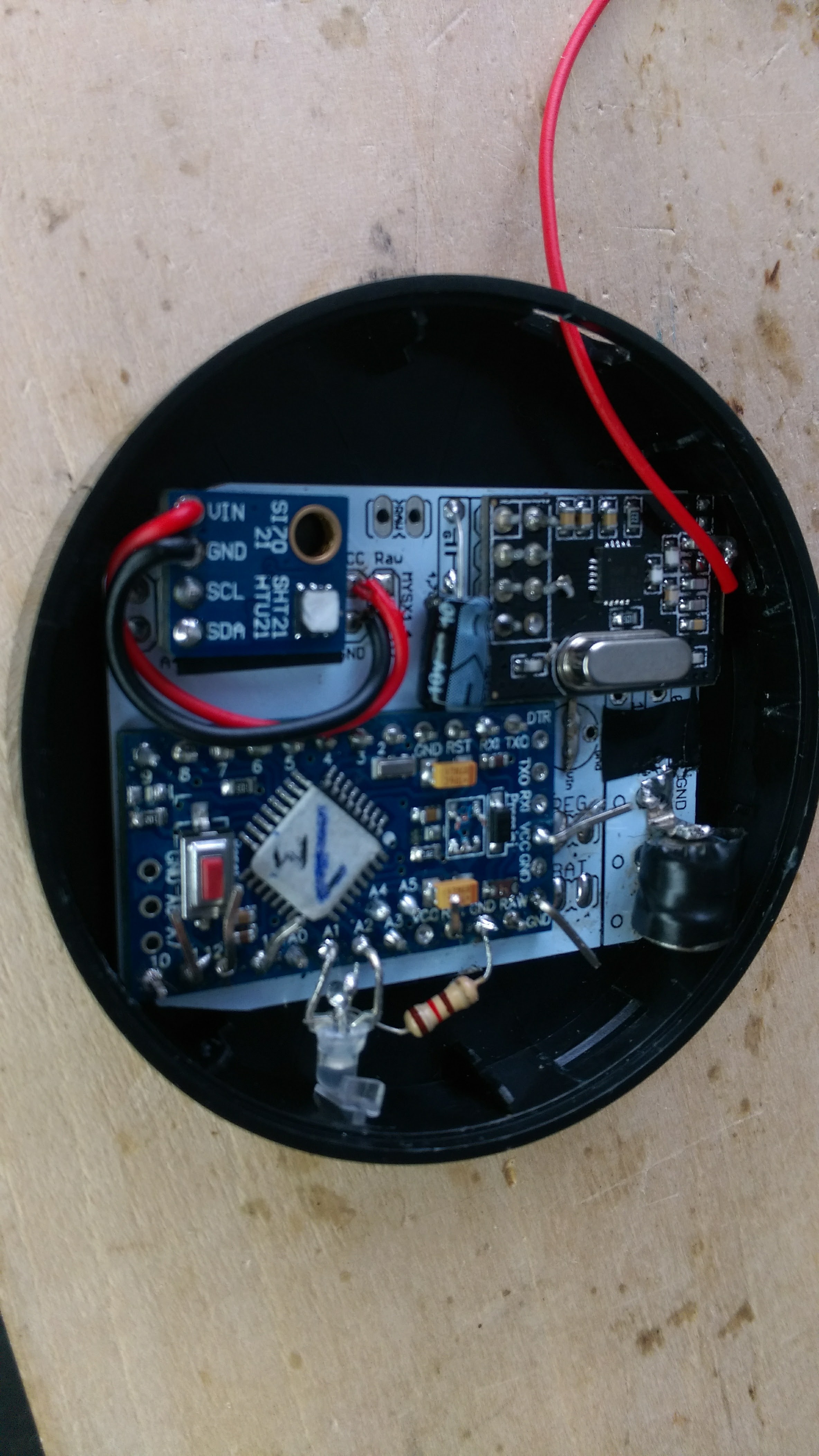
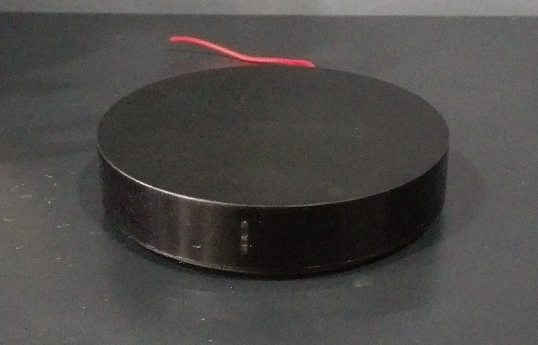
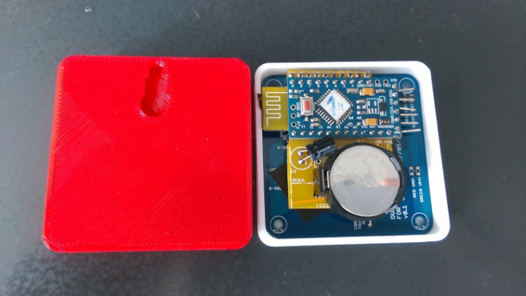
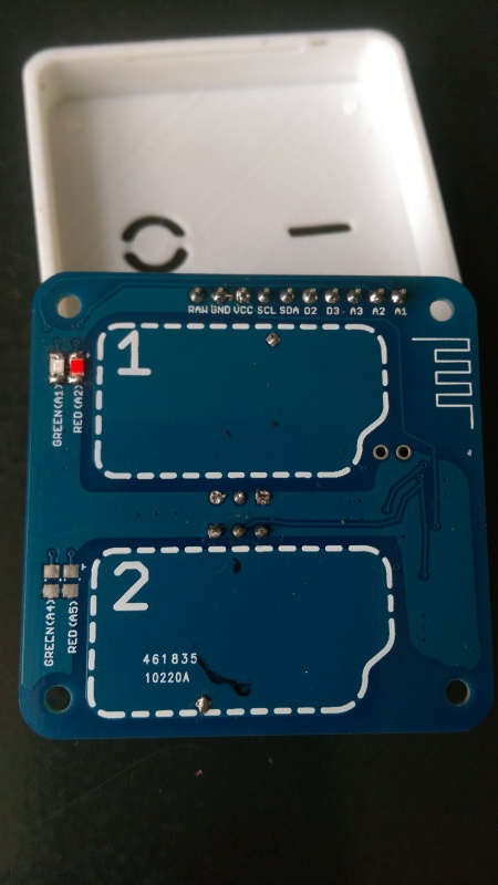
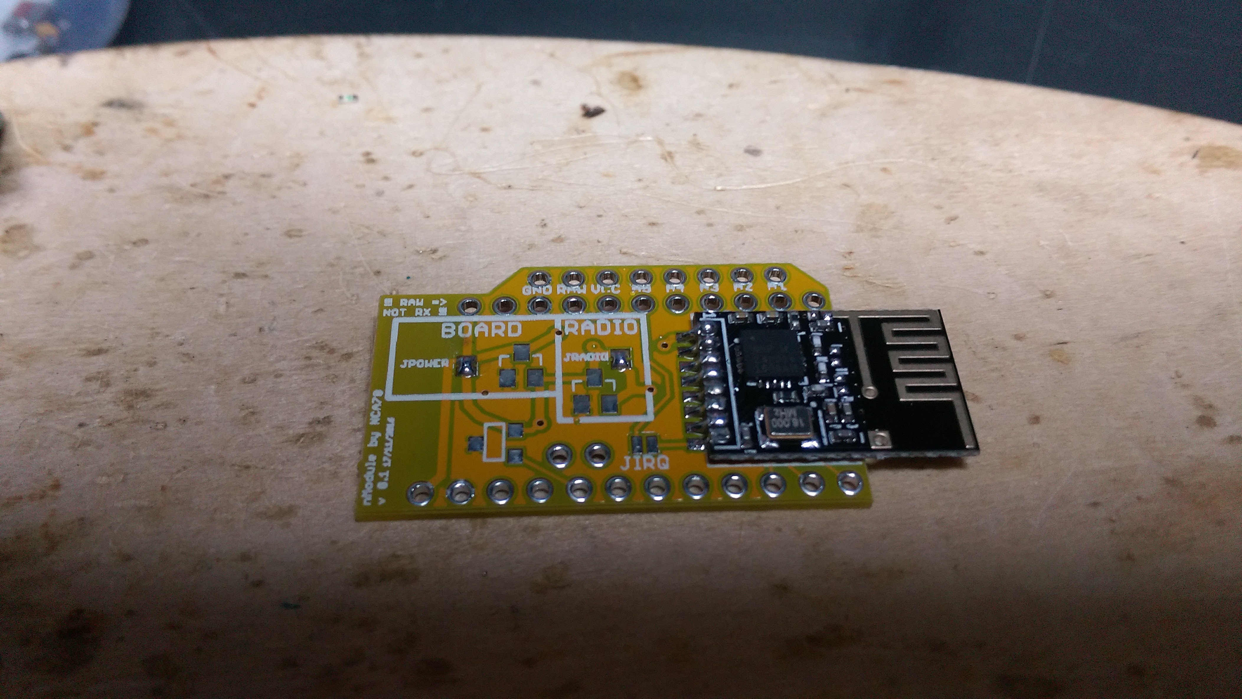
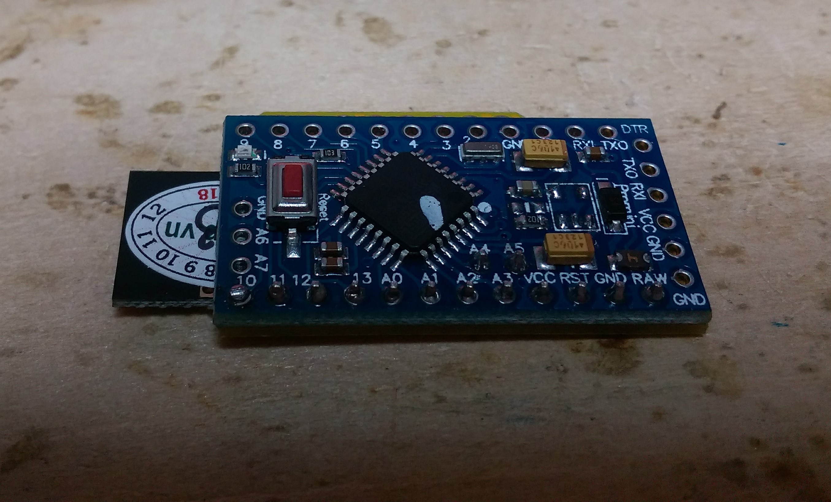
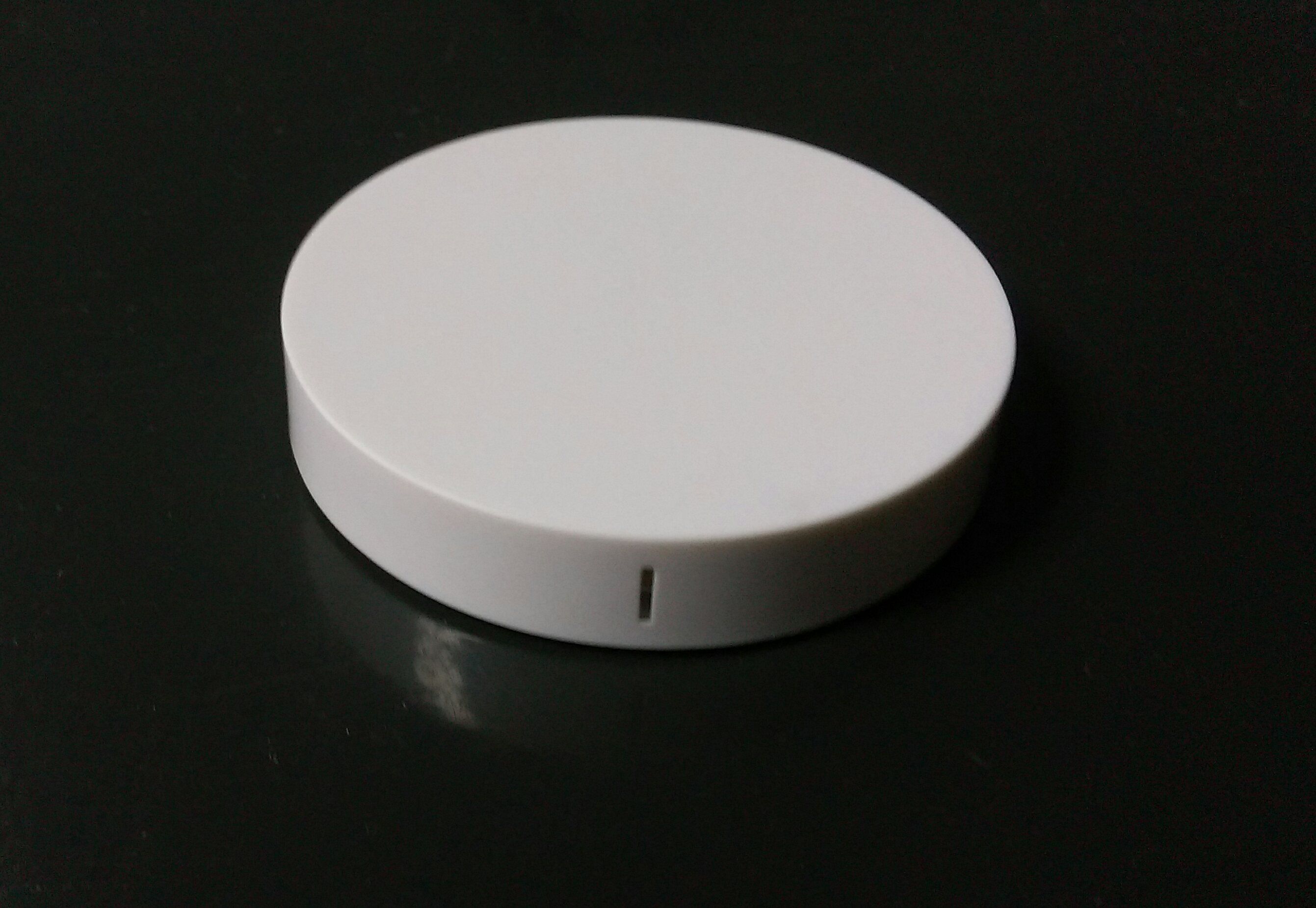
      Then I discovered those great looking wireless chargers and bought 2 different models, they are pretty bad at charging but they look really good. Only problem: they are flat. No way to put a jmodule inside so I went for an EasyPCB and removed the plastic stripes on the headers to make the pcb as flat as possible. I choosed the smaller (but thicker) black one as in the other the PCB + NRF24 was already too thick (because of the crystal).
      https://www.aliexpress.com/item/QI-Wireless-Charger-Charging-Pad-for-Samsung-Galaxy-S7-S6-edge-Note-5-Nokia-HTC-8X/32694769031.html
      https://www.aliexpress.com/item/Factory-price-Qi-Wireless-Charger-Charging-Pad-for-LG-V10-Other-Qi-Phone-Mmar25/32639543557.html

      To fit the pcb I had to remove the right part, and then cut the corners. Still, the antenna of the NRF 24 was too much so I had to cut it too ๐Ÿ˜„ I put a 10cm wire instead, soldered at the beginning of the cut pcb antenna and ... it works really well !
      Unfortunately I couldn't fit a CR2032 after putting the PCB, so I decided to experiment with alkaline button cells, the more convenient solution was to take tiny ones (LR41/AG3) and put them between power connectors of the PCB.
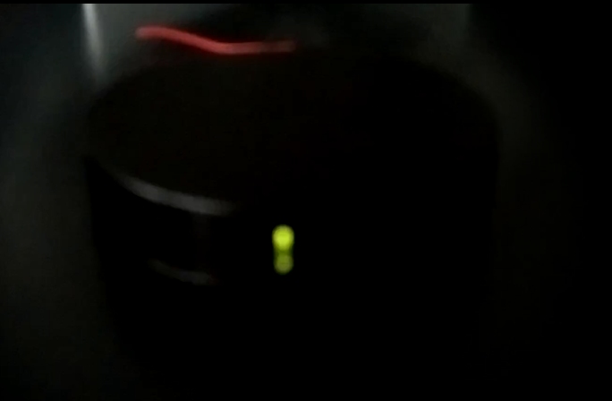
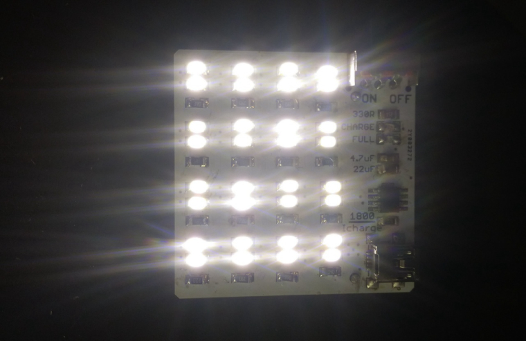
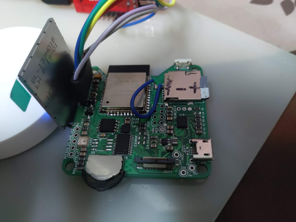
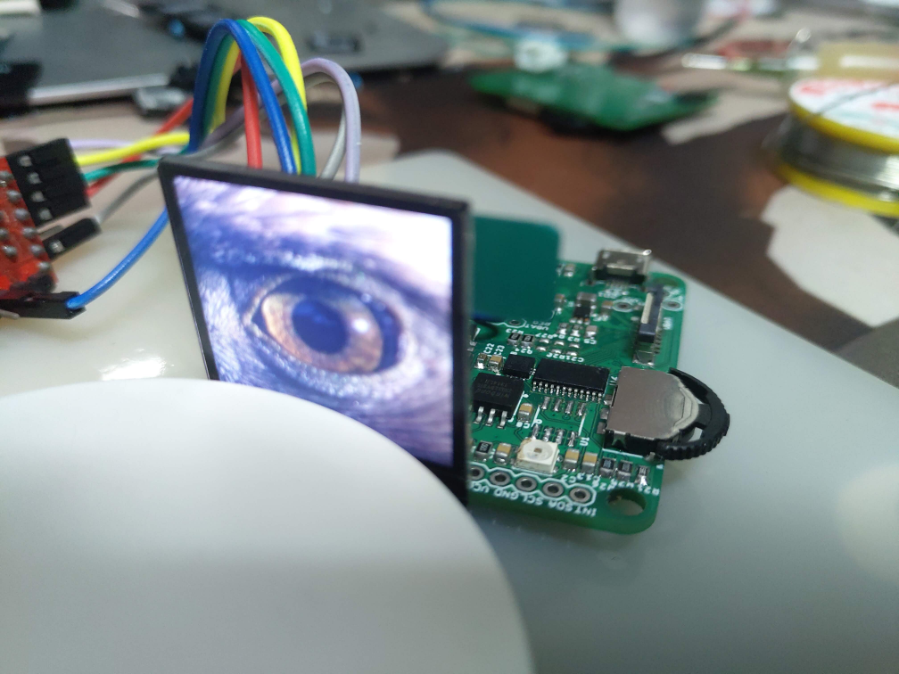
      I also added a bicolor led (green / red) aligned with the led window of the charger, it blinks at each sending loop, wether data is sent or not so I know it's still running. When battery level is high it blinks green, when it gets low it will blink red color so I know it's time to check if I have spare batteries. Also, voltage drop is smaller on red led so it's brighter, green led is dim even at full battery and would be invisible with low battery.

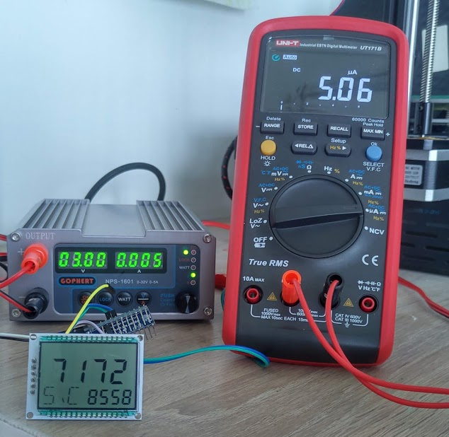
      I use a SHT21 sensor and at the moment I send every minute (if values changed) the temperature, humidity, battery level (%) and battery voltage (to have history). With the led blinking that's a lot to bear for LR41 batteries (rated between 25-30 mAh) but it's done on purpose, to see how fast they get empty.

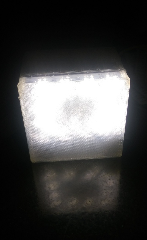
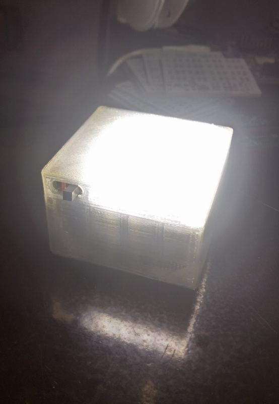
      The PCB ended up pretty atrocious as I did many trials and errors with it (and kept long pins 11,12,13,RST to program the board and have to bend them to fit inside the box) but fortunately when I close the box everything is hidden and the sensor really looks good. With the led flashing it really feels like a commercial sensor you could buy in a shop. I put the sensor not too far from the usb plug hole, but there are also a opening all around the bottom of the enclosure, so I have no visible difference in measure temperature/humidity when I open or close the box.
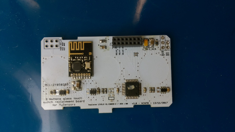
      Next step is a dedicated PCB to have a clean board and be able to fit bigger coin cell(s).

      Wow I'm typing too much ๐Ÿ˜„ Here are the pictures...
      0_1475766817875_IMAG0975.jpg
      0_1475767029388_IMAG0980.jpg
      0_1475766768119_sensor_light.jpg

      posted in Enclosures / 3D Printing
      Nca78
      Nca78
    • RE: Fewer home automation postings? What's behind it?

      Everyone is busy reading your NRF5 thread @NeverDie ๐Ÿ˜„

      posted in General Discussion
      Nca78
      Nca78
    • RE: What did you build today (Pictures) ?

      Today I (finally) finished a full working version of that old Livolo 3 buttons switch. I removed the RGB led on the central button as it's not visible, but the basic switch functionality with buttons/relays and blue/red status leds runs fine.
      It's running with MYSBootloader, it's really convenient to update without having to switch of the fuse and unmount everything.
      0_1515402234037_IMAG2135.jpg

      A (quick) video, touch sensibility is perfect now, I'm really happy with it !
      https://www.youtube.com/watch?v=G6yEdSyoMYw

      posted in General Discussion
      Nca78
      Nca78
    • RE: Fewer home automation postings? What's behind it?

      I have to agree with @skywatch and a few others here, MySensors is relatively easy to start with using the documentation, you wire your pro mini & radio for gateway and sensor and you're running your first sensor in no time.
      But as soon as you want to make things a bit more advanced, you face a lot of challenges that the doc on the website and suggested components make harder to solve :

      • PA/LNA radio that fail, need wrapping in foil to have decent performance etc etc I'm pretty sure this is the most frequent cause of failure for MySensors network.
      • examples with DHT sensors that are not convenient for battery usage => use of step up converters that create a whole set of new problems and unreliability
      • PIR example with SR501 that runs at 5V so you need to alter them to run at lower voltage (3.3V) that's still not so convenient and they become unstable (triggered by radio tx/rx)

      I'll make a list of suggestions to improve the docs, it will probably include writing a few more examples also, and some tutorials for a few things that are easy in fact easy to do but can seem hard from the outside like flashing bootloader on a pro mini or OTA update.

      Currently I have restarted to test my NModule "shields", I will improve and/or fix them and probably convert the most useful ones to MySX Connector.

      posted in General Discussion
      Nca78
      Nca78
    • RE: What did you build today (Pictures) ?

      Working on clearing up the backlog of unfinished NModule shields, today I finished to test the dual touch button shield, made a script to use it as on/off button or as dual button with short press = on and long press = off, as seen below as a dual scene controller.
      https://www.youtube.com/watch?v=064Jlx2eawI

      I made a box so it can be easily customized depending on what you use it for. Unfortunately internet is too bad at the moment in Vietnam to use Fusion 360 so I made it with 123D Design which is less convenient and it's not really high-end assembly ๐Ÿ˜„

      0_1512964810931_IMAG2085.jpg
      0_1512964835281_IMAG2084.jpg

      posted in General Discussion
      Nca78
      Nca78
    • RE: What did you build today (Pictures) ?

      Not related to MySensors but I also assembled a first version of a battery powered led light, it's small and cheap and I will assemble a bunch to put around my home when there are some power cuts in evening/night. I'm using 3020 leds and they emit a lot of light for their small size, even with low current so I expect to get around 2 hours of battery life with the cheap aliexpress 16340 batteries, and way more than needed with the 18650 cells salvaged from my old laptop battery.
      My first board with a li-ion charger and it is working well, now I'm waiting for the battery protection ics (cheap DW01 from AliExpress) to arrive as my batteries are not protected.

      2_1516277652209_IMAG2158.jpg 1_1516277652209_IMAG2159.jpg 0_1516277652206_IMAG2161.jpg

      posted in General Discussion
      Nca78
      Nca78
    • RE: What did you build today (Pictures) ?

      @dbemowsk said in What did you build today (Pictures) ?:

      The nice thing about owning a 3D printer is that I don't have to buy enclosures any more. I just have to buy rolls of plastic. The sky is the limit when you have a 3D printer. I do like that enclosure though.

      Can't agree more, made a quick box for the lights with "crystal" PLA. You need a lot of imagination to believe it's crystal, but it's nice for a light enclosure as it acts as diffuser.
      1_1516534061594_IMAG2164.jpg 0_1516534061592_IMAG2165.jpg

      posted in General Discussion
      Nca78
      Nca78
    • RE: What did you build today (Pictures) ?

      Today, a 5uA always on display with a PCF8553 LCD driver and a GDC1038 LCD from GoodDisplay. Power consumption varies with voltage but mostly with what segments are on/off, but at 3.3V with segments on to display data on all parts of display (2*4 digit numbers and 3 letters) it's always below 6uA.

      cbcf188c-16f4-4b62-be82-a6aaab2cbade-image.png

      Not sure why the Youtube video won't integrate as it should, but here it is for a more animated version:
      Arduino ultra low power LCD (5uA) โ€“ 00:21
      โ€” NicolasVietnam

      posted in General Discussion
      Nca78
      Nca78
    • RE: What did you build today (Pictures) ?

      Today I finished to fix failed soldering (too old solder paste made a mess ๐Ÿ˜ข ) on the "motherboard" of my air quality sensor.
      It's based on ESP32, uses a charging IC with power path so it can run on batteries for around a day or stay plugged without destroying the battery, step down from USB/battery to get VCC, storage on I2C EEPROM, flash and/or ยตSD card (depending on use case), one SK6812 mini RGB led as indicator, a small 240*240 IPS LCD (backlight driven directly by ESP32 pin in high drive capability mode), a 3 way switch for basic user interface + footprint for PAJ7620 gesture recognition module, accelerometer and I2C IO expander to manage the 3 way switch and interrupts from sensor modules.
      Sensor modules will be added on top, connected using an FPC connector. At the moment I made only one sensor PCB able to manage usual PM, CO2 and formaldehyde sensors. Only one sensor per sensor board where an attiny841 manages the UART sensor and convert it to I2C, it also manages the 5V step up to power the sensor.
      On the main board I also added an NRF24 footprint so with the same PCB I will be able to make a gateway with integrated battery backup.

      I'm pretty happy with the relatively well aligned components (no, I don't have OCD ๐Ÿ˜„ ) , too bad I had to unsolder, clean and re-solder each component as it now looks botched up. But at least everything (except a missing connection on ยตSD card, hence the blue wire) is working,
      475bc52b-5bba-450f-aaa0-74eac94a1fb3-image.png

      LCD test showing jpgs from SD card
      c6334b2c-acf5-480f-aca3-c7ad5f191def-image.png

      posted in General Discussion
      Nca78
      Nca78
    • RE: ๐Ÿ’ฌ jModule

      @EddyG said:

      Any news on the new board? I am really interested.

      I'm testing a first version right now ๐Ÿ™‚
      It's running fine but there are some annoying defaults.
      I'm making improvements to the PCB now and I will publish on openhardware.io in the coming weeks.

      I'm using SMD NRF 24 with antenna outside for better reception. Radio capacitor is SMD also but big size (1206) so easy to solder.
      0_1483065250380_onlyradio.jpg

      This is what the assembled board will look like, it takes a bit more surface than jModule but as you can see it's really flat, around 7mm and less than 6mm if you remove the big reset button on the pro mini.
      0_1483065357725_IMAG1205 (2).jpg

      posted in OpenHardware.io
      Nca78
      Nca78
    • RE: Clean looking sensor node

      I just received the white version and it's gorgeous ! Ordering bunch now to put everywhere in the house ๐Ÿ˜„ 0_1480503727105_IMAG1095_1.jpg

      posted in Enclosures / 3D Printing
      Nca78
      Nca78
    • RE: Recommendation for PCB fab?

      It seems there's a fast + good (enough) + cheap options now, AllPCB asks 5$ for 10 boards up to 100*100mm, it's limited to 1.6mm, green or white color (take the green, quality of the white silkscreen is not good, not fitting between pads of an atmega328 for example).
      Doesn't sound like a great offer now, but there are some insane things :

      • the "top speed" option is included meaning your board are done in 2-3days after order
      • there is free shipping with HK Post
      • there is free shipping ... with DHL ๐Ÿ˜ฎ

      Result is boards received 6 days after placing orders, very impressive !
      And good point I order 10 but for the biggest bord (98*98mm) I received 12, and for the smallest I received... 34 while with another small board I received around 20.

      So if you want to test your boards quickly and don't mind the 1.6mm thickness in green color, this is the perfect offer. Every option that you will select (color, thickness, panelization,...) will make the price increase quickly, but it's a good way to test functionality of your board quickly then order fancy colors/thickness etc from another fab when your board is completely designed.

      posted in General Discussion
      Nca78
      Nca78
    • RE: ๐Ÿ’ฌ Livolo 3 buttons US/AU switch adapter

      https://youtu.be/0z4vhWA3xJ8

      posted in OpenHardware.io
      Nca78
      Nca78
    • RE: What did you build today (Pictures) ?

      @sundberg84 said in What did you build today (Pictures) ?:

      And want to make a tip about smd component organisation...

      I think we should make another topic for this kind of tips ? We could discuss pros and cons and give reference to online shops to buy items, your boxes are quite nice for DIP components and small breakout boards, where are they from ?

      For SMDs components I went for the lab supplies on AliExpress, I started to sort my SMD chips using 5ml tubes and 3D printed holders, I need to print more holders to sort by categories as it's a bit messy at the moment. I put a bigger sticker on the side of tubes with more details as top sticker is pretty small ๐Ÿ˜„ Same holders can also holder bigger tubes for bigger stuff like here mini/micro USB plugs.
      0_1514559330846_IMAG2118.jpg

      For resistors, capacitors, inductances, ... I went for lab tube boxes. I use smaller tubes (1.5 or 2ml) but they can hold probably thousands of 0603 or 0402 and even hundreds of the 0805 and 1206 resistors. I use different colors to differentiate size (and later precision/voltage/... when I'll have more boxes) and put bigger stickers on the lid of the box with information for each color.
      0_1514559354052_IMAG2119.jpg

      posted in General Discussion
      Nca78
      Nca78
    • RE: Safe In-Wall AC to DC Transformers??

      I confirm about the fake ones. I just received a batch of fake ones from GREATWALL shop on aliexpress (seller with good reputation and used for many items on the MySensors shop...) and I'm filing a dispute right now, as the seller acknowledge they are different but pretend it's because HiLink is replacing their factory. Makes no sense if you replace your factory to set up a new line to build different modules ๐Ÿ™‚ This seller is also selling the Tenstar TP-0x modules pretending they "replace" the HLK so I suppose the one I received are tenstar modules disguised as HLK.

      They are obviously fakes and lower quality, as can be seen from the pins (thinner, and with no blocking mecanism so pins go inside the module when pushed), obvious lower quality with the gray material filling and very different looking plastic.
      I'll see how the dispute goes and after it's closed/solved I'll open one.

      0_1473300677126_HLK1.jpg
      0_1473302054227_HLK2.jpg

      posted in Hardware
      Nca78
      Nca78
    • RE: What did you build today (Pictures) ?

      I printed a small box and put my first "22" board in action on my entrance door. So far so good it's reporting the status reliably, and looking really tiny. A big difference with my first sensor 2 years ago in a big generic project box.
      Just need to clean the glue left from previous sensor now ๐Ÿ™‚

      0_1523359333638_IMG_20180410_171653.jpg

      0_1523362545558_IMG_20180410_191112.jpg

      posted in General Discussion
      Nca78
      Nca78
    • RE: pro mini programming

      I vote for the 3.3V all the time rule. I have a jumper on my ftdi adapter but I don't touch it anymore, too dangerous when you forget to put it back.

      posted in Hardware
      Nca78
      Nca78
    • RE: 8Bit or 32Bit processors

      @NeverDie it depends on your application.
      For example ATSAMD20E18A-AU is just over 2$, same price than atmega328 if you buy from a "reputable" source.
      But it has many more capabilities that will save you external components: easier/faster design, lower power consumption, easier coding etc etc.

      I had a quick look at the datasheet and see many potential interesting uses for me :

      • it can manage dozens of touch channels meaning I could use a much more simple design for the board in Livolo wall switch. And with 8uA in sleep mode with capacitive touch enabled it's saving power too
      • it has 6 serial communication interfaces so it can have 2 high speed serial coms and manage A6 GSM module in debug mode, something I can't do with atmega328 but only with a mega2560 which is much more expensive
      • integrated RTC so no need for it on my ADXL shield for example. And in sleep mode with RTC active it's using less current than atmega328 with watchdog timer activated for regular wake up.

      Even if you buy atmega328 around 1$ on aliexpress you can quickly make your missing $ back in many use cases.
      I'm seriously thinking about using it now ๐Ÿ™‚

      posted in Hardware
      Nca78
      Nca78
    • Additional sleep methods with array of pins as parameters ?

      Hello,

      is there any plan to add new sleep methods that would take an array of pins instead of the 2 interrupt pins ?
      Use cases would be :

      • have more than 2 interrupts on atmega and more flexibility on pin numbers, this would use pin change interrupts
      • be able to make battery powered sensors on NRF51 as hardware is still bugged even in the last versions of the chip. So it's either LPCOMP (but that limits to one interrupt pin only and only on pins 1-8) or PORT mode with pin sense which has a similar behavior than pin change on atmega (one interrupt for all activated pins).

      So it looks like a good opportunity to kill two birds with one stone: have an "official" implementation of pin change interrupt for atmega, and unblock nrf51 users and probably also nrf52 users who need many interrupts.
      Of course this need some "preparation" of the data so that it's easier for user to know what pin generated the interrupt. I'm not sure what is the best solution for this, app_gpiote.c from nrf5 SDK returns 2 masks for low=>high and high=>low pins but it doesn't seem to be so newbie-friendly.

      If core team and/or @d00616 (for nrf5 part) think it's a good idea and we agree on how it's best to implement it I'm ok to prepare some pull requests.

      posted in Feature Requests
      Nca78
      Nca78
    • RE: ๐Ÿ’ฌ NModule

      Christmas in June ! ๐Ÿ˜„

      0_1496635055360_IMAG1734.jpg

      posted in OpenHardware.io
      Nca78
      Nca78
    • RE: Alternatives for nRF24L01+ ?

      @NeverDie said in Alternatives for nRF24L01+ ?:

      That said, I'm not at all sure the CDEbyte is any better than the cheaper alternative, which includes an antenna: https://www.aliexpress.com/item/5pcs-Free-Shipping-Special-promotions-1100-meter-long-distance-NRF24L01-PA-LNA-wireless-modules-1100meters-with/1037554818.html?spm=a2g0s.9042311.0.0.3qUb1A

      I never got good resuts with similar pa/lna modules. Some work, some don't, some do only after tinkering.
      With the one from CDEByte it just gave instant coverage to all my nodes, no tinkering necessary and nothing like what @manutremo is describing above. My nodes which had problem to report from the other side of my appartment became 100% reliable.

      posted in General Discussion
      Nca78
      Nca78
    • RE: ESP8266 questions before buying

      I vote for the Wemos D1 Mini too, if you take the real one from Wemos and not the clones.
      If you buy from Wemos (they have a shop on aliexpress) you are sure to get a good quality board with the last version of ESP8266 (4Mb + better antenna) while the clones and probably all the NodeMCU you find on aliexpress/ebay are made as cheap as possible by various suppliers and you can't be sure of what you really get.

      And for battery powered sensors, arduino + radio is the only viable solution for long battery life.

      posted in Hardware
      Nca78
      Nca78
    • RE: ๐Ÿ’ฌ Aeos : a NRF52 versatile, up to 9in1, device

      @scalz have you seen this module ?
      PCB antenna + IPEX, and with 52832 we're sure it's not a clone...
      At this price I can directly dump my atsamds and nrf modules ๐Ÿ˜ฎ
      http://www.ebay.com/itm/nRF52832-E73-2G4M04S-Low-Power-2-4GHz-SMD-Wireless-Module-with-PCB-IPX-Antenna-/192237288810

      posted in OpenHardware.io
      Nca78
      Nca78
    • RE: What did you build today (Pictures) ?

      Today I soldered a tiny MYSX board to recycle my EasyPCBs in door sensors as compact as possible. I can also use the "vertical" CR2032 holders I had no use for and make some space in my drawers.
      It can use a normal or a NO/NC reed switch (for SMD allergies ๐Ÿ˜„ ) or a SMD ultra low power hall sensor and it has a footprint for a reserve capacitor to support the CR2032.
      I guess this board will be of interest for @sundberg84 ๐Ÿ˜‰

      2_1516276346915_IMAG2152_1.jpg 1_1516276346913_IMAG2151_1.jpg 0_1516276346910_IMAG2150.jpg

      PS: sorry for the ugly soldering, my old 936 clone soldering station is in "zombie" mode and it's all I have until the new soldering iron arrives.

      posted in General Discussion
      Nca78
      Nca78
    • RE: head's up: LGT8F328P is allegedly a chinese clone of the atmega328p

      Looks like the same chip than in the Wemos XI.
      I didn't manage to get a decent sleeping consumption with it so I gave up. Didn't try too much to be honest, I didn't see the interest in wasting time to pay the board 1$ instead of 2.
      It's far from a perfect clone, it has enough differences to need a different arduino core.

      posted in Hardware
      Nca78
      Nca78
    • RE: ๐Ÿ’ฌ Micro (nano) ampere meter (double)

      @rvendrame said in ๐Ÿ’ฌ Micro (nano) ampere meter (double):

      @Nca78 , my HX711 board looks like yours. I'm a bit confused on how to connect the J1 pins to the load / power. Can you share how did you connected it? Thx!

      Soldering is a bit messy and not helping much to understand, so I did a (gorgeous) drawing. I think I'll frame that in my living room ๐Ÿ˜„
      0_1499396932760_HX711.png

      And in case you want to increase the data rate
      0_1499397497585_hx711_2.jpg

      posted in OpenHardware.io
      Nca78
      Nca78
    • RE: 6/8 Buttons battery remote node

      You can :

      • use another IC that is not so cheap about external interrupts (ex: nrf5)
      • connect each button to pin 3 through a diode so your board will wake up, then check each input pin to know which button is pressed
      • use pin change interrupt, it works but you need to write your own sleep method as it's not in the options of the MySensors sleep
      • use an extender ic (for example sx150x but there are cheaper and easier to solder options) or a touch ic (for example mpr121) and use their interrupt pin to wake up your board, then retrieve data through I2C
      posted in General Discussion
      Nca78
      Nca78
    • RE: Favorite hand solderable radio chip?

      @monte said in Favorite hand solderable radio chip?:

      @NeverDie stencil would help, for sure. But I am talking bare minimum. You tin the pads a little, so they are like bumps, then apply gel flux, put the IC aligned to the pins and reflow it with hot-air gun. That may be not the best practice, but it works, if you need to solder few IC's.

      I confirm it works, if you don't put too much solder. I do like this with TSOP style packages too, because it's way easier than using a soldering iron.

      posted in Hardware
      Nca78
      Nca78
    • RE: ๐Ÿ’ฌ NModule

      @sundberg84 I'm working on it ๐Ÿ™‚

      posted in OpenHardware.io
      Nca78
      Nca78
    • RE: What did you build today (Pictures) ?

      I made a working version of my test board with PCF85176 LCD driver, finally reaching some decently low current consumption for an always on display. There are still some possible gains to make with lower driver voltage, and with a more recent driver that should allow to go as low as 5uA.

      alt text

      posted in General Discussion
      Nca78
      Nca78
    • RE: ๐Ÿ’ฌ TI CC2640 BLE Plug-in module for MSP430 LaunchPad

      This is looking a lot like advertising for your modules to me...

      posted in OpenHardware.io
      Nca78
      Nca78
    • RE: Mi-Light controller for Mysensors

      Hello, few months have passed and I finally had a look at the code from @Jason-Brunk
      I made a MiLightBulb class with methods to set on/off, set brightness level, set color and set animation. It still needs improvements as brightness is not working, some colors are a bit off and I didn't test animation yet but it's starting to take shape and I can use it from RGB light control in domoticz.

      I have connected 2 nrf24 also, using pins 7&8 for the one sending MiLight messages instead of 9&10 and it running fine as expected, no use to call begin() all the time: much more reactive.
      I'll publish the code as soon as I have time to finish and clean up.

      posted in My Project
      Nca78
      Nca78
    • RE: BlackBox: binary, lightweight communication protocol handler source code generator.

      @sirguy-cheblin said in BlackBox: binary, lightweight communication protocol handler source code generator.:

      @gohan do you use MQTT? well. forget it.
      With BlackBox you can build your own, fit to only your project needs.

      What's the advantage of leaving an interoperable protocol like MQTT for your own protocol ?
      And how is it relevant in a MySensors environment ?

      posted in My Project
      Nca78
      Nca78
    • RE: Are folks here happy with Domoticz?

      I've been using Domoticz for a while, because it was the most obvious system to use with my RFXTRX433 and my 433MHz modules.
      I agree with what has been said: very easy to setup, nice graphs/history but limitations in UI are very frustrating. There's a nice API too, but I'm not feeling like reprogramming the full UI to have something that I enjoy.
      I'm getting frustrated with the programming of events too, for very basic scenarios it's fine, but the way it works can quickly make it a mess. For example if you switch a light in a script it will re-trigger scripts based on light switching and you have no way to know if it was triggered by user action or by script, so you you have to start using global variables (declared in another part of the UI) to keep that information etc etc

      So, I'll start my controller shopping season too relatively soon I think ๐Ÿ™‚

      posted in Domoticz
      Nca78
      Nca78
    • RE: Battery power (cr2032) on 2.0?

      Hello,
      I have door/window sensors working with CR2032 cells with good results.
      Problem with those batteries is they can only provide a very low current, they have a relatively high internal resistance, so the more current you draw from them, the more energy you waste through this internal resistance, and the more the voltage drops. You need to use a few tricks to compensate, and then it's all fine.

      I do the following things to have good results and from what I see until now, good battery life:

      • use pro mini 3.3V / 8 MHz, put 1MHz bootloader so you can set BOD at 1.8V. No regulator/step up or anything similar, it would kill the battery.
      • put a 200uF capacitor in parallel with your battery. If you have a temp/humidity sensor sending with long intervals you could be fine with 100uF but it's not the case if I open/close a few times my door/windows.
      • never have 2 data sending actions without a sleep in the middle. I use a 250ms sleep between sending in the presentation() method, and 100ms in the code (when I send battery level after status, it's not all the time)
      • use branded cells and not the cheap chinese stuff from aliexpress/ebay, there is really a difference !
      posted in Hardware
      Nca78
      Nca78
    • RE: ๐Ÿ’ฌ ESP-LINK ESP8266 WeMos D1 Mini Adapter Board

      @NeverDie said:

      @kalle said:

      I have bought all my Wemos D1 (30 pcs) from the original seller to get sure they work and they do.

      https://de.aliexpress.com/store/1331105

      I would do the same, except the original seller doesn't ship by ePacket delivery. I'm guessing less expensive clones are probably fine for experimenting with, but for an install that needs to last for years and not fail I imagine Wemos (aka "the original seller") maybe has more reason to care about quality control and not cut corners since it's their branded name on the line.

      I'm curious to know: what is it you're doing that requires 30 D1 Mini's?

      Obviously when looking at the clones up there, Wemos is the one cutting the corners... of the PCB ๐Ÿ˜‰
      Bought mines from Wemos too, ESP8266 board tend to be very unstable without a good power supply and I prefer paying 1โ‚ฌ more than waste hours if not days trying to solve a problem that's due to a cheap component. A bad experience with a nodemcu board has vaccinated me...

      posted in OpenHardware.io
      Nca78
      Nca78
    • RE: gw.sleep on battery powered magnet door switch

      @Nicklas-Starkel said:

      @siod , I had the same problem.
      I actually ordered a original NRF 24 mini and this seemed to solve some of my problems.
      i think another problem I'm having is that my batteries has a huge self discharge (old 3.7v 18650)

      On a side note.. I'm with @sling .
      Loose the pullups and set them LOWยด.
      I have a 1MOhm resistor between VCC and PIN 2 and PIN 3 (also 2 switches).
      Using the pullup HIGH draws around 130uA versus LOW it draws between 7 to 10uA!

      That's the best solution with a normal reed switch.
      But the best way is to use a "double" reed switch, with both normally opened and normally closed contacts. I use that connected between GND and pin 2 & 3 and set only the unconnected pin to high (so, with pullup). Current will flow only a very short time through the pullup while the node is waking up from sleep, then first thing I do is set connected input low. So nearly 100% of the time input is not connected and current through the reed switch is 0.
      I've put a test node on my entrance door, it's been running for over 3 months on a CR2032 cell and has lost only 0.02V meaning it will last at least 2 years, maybe 3.

      /**
       * The MySensors Arduino library handles the wireless radio link and protocol
       * between your home built sensors/actuators and HA controller of choice.
       * The sensors forms a self healing radio network with optional repeaters. Each
       * repeater and gateway builds a routing tables in EEPROM which keeps track of the
       * network topology allowing messages to be routed to nodes.
       *
       * Created by Henrik Ekblad <henrik.ekblad@mysensors.org>
       * Copyright (C) 2013-2015 Sensnology AB
       * Full contributor list: https://github.com/mysensors/Arduino/graphs/contributors
       *
       * Documentation: http://www.mysensors.org
       * Support Forum: http://forum.mysensors.org
       *
       * This program is free software; you can redistribute it and/or
       * modify it under the terms of the GNU General Public License
       * version 2 as published by the Free Software Foundation.
       *
       *******************************
       *
       * DESCRIPTION
       *
       * Interrupt driven binary switch example with dual interrupts
       * Author: Patrick 'Anticimex' Fallberg
       * Connect one button or door/window reed switch between 
       * digitial I/O pin 3 (BUTTON_PIN below) and GND and the other
       * one in similar fashion on digital I/O pin 2.
       * This example is designed to fit Arduino Nano/Pro Mini
       * 
       * NCA78: Updated to work with one dual normally open/normally closed reed switch on both interrupt pins.
      
       */
      
      
      // Enable debug prints
      //#define MY_DEBUG 
      
      // Enable and select radio type attached
      #define MY_RADIO_NRF24
      
      #include <SPI.h>
      #include <MyConfig.h>
      #include <MySensors.h>
      #include <SystemStatus.h>
      #define SKETCH_NAME "NCA Door Sensor"
      #define SKETCH_MAJOR_VER "0"
      #define SKETCH_MINOR_VER "7"
      
      #define PRIMARY_CHILD_ID 3
      
      #define PRIMARY_BUTTON_PIN 2   // Arduino Digital I/O pin for button/reed switch
      #define SECONDARY_BUTTON_PIN 3 // Arduino Digital I/O pin for button/reed switch
      
      #if (PRIMARY_BUTTON_PIN < 2 || PRIMARY_BUTTON_PIN > 3)
      #error PRIMARY_BUTTON_PIN must be either 2 or 3 for interrupts to work
      #endif
      #if (SECONDARY_BUTTON_PIN < 2 || SECONDARY_BUTTON_PIN > 3)
      #error SECONDARY_BUTTON_PIN must be either 2 or 3 for interrupts to work
      #endif
      #if (PRIMARY_BUTTON_PIN == SECONDARY_BUTTON_PIN)
      #error PRIMARY_BUTTON_PIN and BUTTON_PIN2 cannot be the same
      #endif
      #if (PRIMARY_CHILD_ID == SECONDARY_CHILD_ID)
      #error PRIMARY_CHILD_ID and SECONDARY_CHILD_ID cannot be the same
      #endif
      
      #define MY_PARENT_NODE_ID 0
       
      
      // Change to V_LIGHT if you use S_LIGHT in presentation below
      MyMessage msg(PRIMARY_CHILD_ID, V_TRIPPED);
      //MyMessage msg2(SECONDARY_CHILD_ID, V_TRIPPED);
      
      
      // Parameters for VCC measurement
      const int VccMin        = 2000;  // Minimum expected Vcc level, in Volts. At 2V the cell should be dead
      const int VccMax        = 2900;  // Maximum expected Vcc level, in Volts.
      SystemStatus vcc();
      int LastBatteryPercent = 200; // so we are sure to send the battery level at first check
      bool isEven = false; // to check+send battery level only for each open+close cycles
      
      bool revertValue = false;  // to change this put a jumper on D4/D7 and it is tested at startup
      
      
      // This is the activated pin, on which the interrupt is set
      byte connectedPin = PRIMARY_BUTTON_PIN;
      byte connectedPinAtLastSending = 0; // Initialized at 0 so we will always send the first time
      
      void setup()  
      {  
        // First thing to do: change clock prescaling to 8 to change from 8MHz to 1MHz
        //  of course not necessary if you already have updated fuses and bootloader...
        #ifndef MY_DEBUG           // only if we are not in debug mode, so we can keep the fast baudrate in debug
          clock_prescale_set (clock_div_8);   
        #endif


      }
      
      void presentation() {
        sleep(250); // sleep to let capacitor recharge a bit
        // Send the sketch version information to the gateway and Controller
        sendSketchInfo(SKETCH_NAME, SKETCH_MAJOR_VER "." SKETCH_MINOR_VER);
        sleep(250); // sleep to let capacitor recharge a bit
        // Register binary input sensor to sensor_node (they will be created as child devices)
        present(PRIMARY_CHILD_ID, S_DOOR);
        sleep(250); // sleep to let capacitor recharge a bit
      }
      
      // Loop will iterate on changes on the BUTTON_PINs
      void loop() 
      {
        // Short delay to allow buttons to properly settle
        sleep(5);
      
        deActivatePin(PRIMARY_BUTTON_PIN);
        deActivatePin(SECONDARY_BUTTON_PIN);
      
        // Check if the previously connected pin is now connected. We do that because it's the most likely to be unconnected now
        //  so it's the best way not to lose any current
        byte newConnectedPin = GetNonConnectedPin();
        if (checkPinIsConnected(connectedPin)) {
          // If pin is still connected we set back the value to connected pin
          newConnectedPin = connectedPin;
          #ifdef MY_DEBUG
            Serial.println("Connected pin is connected !");
          #endif
          
        }
        connectedPin = newConnectedPin;
        // If connected pin is different that the one during the last sending of status, we send again
        #ifdef MY_DEBUG
          Serial.print("Connected pin = ");
          Serial.println(connectedPin);
          Serial.print("New Connected pin = ");
          Serial.println(newConnectedPin);
        #endif
        
        if (connectedPin != connectedPinAtLastSending) {
           // Value has changed from last transmission, send the updated value
           send(msg.set(connectedPin==PRIMARY_BUTTON_PIN ? (revertValue ? 0 : 1) : (revertValue ? 1 : 0)));
           connectedPinAtLastSending = connectedPin;
           isEven = !isEven;
        }
        
        if (isEven) {  // send only every two changes for a full open + close cycle
          int currentBatteryPercent = SystemStatus().getVCCPercent(VccMin, VccMax);
          if (currentBatteryPercent != LastBatteryPercent) {
              sleep(100); // sleep 100ms (+65ms wake up time) to let capacitor recharge a bit
              LastBatteryPercent = currentBatteryPercent;
              sendBatteryLevel(currentBatteryPercent);
          }
        }
      
        #ifdef MY_DEBUG
          Serial.print("Preparing to sleep, pin ");
          Serial.println(GetNonConnectedPin());
          wait(50);
        #endif
      
        // Activate the non connected pin before setting up interrupt
        activatePin(GetNonConnectedPin());    
        // Sleep until something happens with the door sensor
        sleep(GetNonConnectedPin()-2, CHANGE);
      } 
      
      void activatePin(byte pin) {
        // Set pin as input
        pinMode(pin, INPUT);
        // Activate internal pull up
        digitalWrite(pin, HIGH);
      }
      
      void deActivatePin(byte pin) {
        // Set back pin as output, low
        pinMode(pin, OUTPUT);
        digitalWrite(pin, LOW);
      }
      
      // Will check if pin is grounded (returns true) or not
      boolean checkPinIsConnected(byte pin) {
        activatePin(pin);
      
        // Read value
        byte valPin = digitalRead(pin);
        deActivatePin(pin);
      
        #ifdef MY_DEBUG
          Serial.print("checkPinIsConnected pin = ");
          Serial.print(pin);
          Serial.print(", value = ");
          Serial.println(valPin);
        #endif
        
        return valPin != HIGH;
      }
      
      // Returns the pin that is not connected
      byte GetNonConnectedPin() {
        return (connectedPin == PRIMARY_BUTTON_PIN) ? SECONDARY_BUTTON_PIN : PRIMARY_BUTTON_PIN;
      }


      https://www.aliexpress.com/item/20pcs-lot-3-pin-Reed-Switch-2-5X14MM-GLASS-Green-3-pin-Normally-Open-and-Normally/32507762756.html?spm=2114.13010608.0.0.4LJb9I

      posted in My Project
      Nca78
      Nca78
    • RE: Switchcases?

      You can also use this solution. It's not extremely cheap but it's all already done, you can reprogram the ESP8266 inside to put a MySensors gateway sketch.

      https://www.itead.cc/smart-home/smart-socket-eu.html

      posted in Hardware
      Nca78
      Nca78
    • RE: ๐Ÿ’ฌ ESP-LINK ESP8266 WeMos D1 Mini Adapter Board

      Just received mine and it's great as it's really thin now. They have moved the USB plug on the same slide than the components and every other component is thinner than that.
      Not sure about the reception quality with the ceramic antenna but it could be a good improvement too.

      The problem is when you want to use the 16Mb. It's not supported by Arsuinonso you have to cheat. And it's not even supported by the read/write flash functions so you have to cheat also. In both cases you don't have full functionality for the 16Mb using Arduino...

      posted in OpenHardware.io
      Nca78
      Nca78
    • RE: coin-cell (CR2032) powered temperature sensor

      Hello,

      there are a few improvements you can do to make your CR2032 nodes last longer:

      • add a capacitor of 100-200ยตF in parallel with your battery. Ceramic is better, but I have no problem with nodes using electrolytic capacitors. This will help when there is a peak power consumption from the radio. If you do not put one, voltage will drop quickly and that's probably what is triggering reboot loop on one of your nodes: maybe radio is less efficient and needs to resend more messages. Or maybe your BOD is not updated so it resets when voltage drops at 2.7V...
      • in your code, add a sleep command between message sending to give time for your cell to rest, and for the capacitor to recharge. Do it also at the beginning of presentation method and between each message sending in presentation.
      • use a better sensor that can accept a lower voltage, they are more expensive that DS18 but they can work down to 2V and use much less current: BMP180/280 if you want to measure only temperature (with barometer as extra), SI7021 for temp/hum, BME280 for temp/hum more expensive but better.
      • do not use voltage divider at all, you don't need one as you can just get Vcc from the A0 pin (with it I have some change of voltage related to temperature but not as wild as you seem to get. Maybe it's related to the DS18 measurement also ?)

      With these changes and a si7021 breakout board from which I removed the voltage regulator (it's not consuming much, but without it is even better), I can send every minute, flash a led and I hardly see any drop in voltage after a few weeks of running.

      posted in My Project
      Nca78
      Nca78
    • RE: dht11 CR2032 longevity

      @fhenryco said:
      CR2032 .... step up regulator

      Save your time, the answer is no ๐Ÿ˜‰
      You cannot use a step-up converter with a button cell, it will die in days at best.
      You need to :

      • use a sensor that will accept low voltage, for example si7021/sht21 or BME280
      • remove voltage regulator and led on the pro mini (and use 8Mhz / 3.3v one)
      • update bootloader/fuses so the BOD (which will reset arduino under a minimum voltage) is set lower, typically to 1.8V instead of 2.7V by default. For that you can use another arduino as a programmer, there are many tutorials around
      • add a capacitor (100-200ยตF typically) parallel to the battery to help it during radio transfers
      • in your script, go to sleep between consecutive data sending to let the capacitor recharge
      posted in Hardware
      Nca78
      Nca78
    • RE: ๐Ÿ’ฌ MyMultisensors

      @particle said:

      Thank you so much, so I will buy 16V for 1u capacitor or more, and 6.3V for others.

      No, it's the opposite ๐Ÿ˜„
      The higher the voltage rating, the more leakage/losses you will have. It's not important for small capacitors, but for reserve capacitors like 100ยตF it's better to take as low as possible, basically 2x the voltage used on your board.
      Honestly it's not a big issue if you use 16V instead of 6V, but with a board as optimized for battery life as this one, it would be sad not to optimize the capacitors also ๐Ÿ˜‰

      posted in OpenHardware.io
      Nca78
      Nca78
    • RE: nRF5 action!

      Just discovered this, bought with no wifi (no need for it) and usb adapter. It's using a SAMD21E17 (so 16k/128k) but should be enough for playing a bit and I love the stackable usb adapter that you need to buy only once for all your boards.
      http://www.wino-board.com/store/en/basic-modules/16-winoboard.html

      posted in My Project
      Nca78
      Nca78
    • RE: dht11 CR2032 longevity

      And no, no problems with AA/AAA regarding internal resistance. You can draw a lot of power from them without problem, so you don't need a capacitor for that. Just keep the capacitor for the radio.

      posted in Hardware
      Nca78
      Nca78
    • RE: ๐Ÿ’ฌ Easy/Newbie PCB for MySensors

      @dbemowsk in fact current is leaking through the regulator when its input is floating, you can check the "reverse leakage current" value on the data sheet of the linear regulator used on your promini boards then decide if you can accept it or not, depending on your circuit.

      posted in OpenHardware.io
      Nca78
      Nca78
    • RE: nRF5 action!

      @NeverDie said in Minimalist SAMD21 TQFP32 Pro Mini:

      @Nca78

      Both the price and size are certainly nice. I think d00616 would probably point out that it lacks a 32Khz crystal, but since I lack experience with the nRF5's, I don't know how significant that is or isn't. Anyone know?

      Right, it sucks for low power at it needs recalibration every 4 seconds to stay accurate enough, generating 10uA extra consumption. But I'm not sure if this is needed for bluetooth only (because it has to wake up regularly and listen during a precise time window), or also for "nrf24" mode because in that mode we don't need to be precise or regular listenin.

      posted in My Project
      Nca78
      Nca78
    • RE: What's the best PIR sensor?

      I have received:

      • AM312 based complete PIR sensors, basic sensor with Vcc, GND and output. Claimed consumption on datasheet 20ยตA.
      • AM612 PIR sensors (sensors only). This include all the circuitry in the metal cap, so you only have to add basic components like caps and resistors to set parameters: sensibility, trigger duration. Claimed consumption on datasheet: 15uA.

      I'll try to test them this week to first see if the claims are true (or at least, not too optimistic ๐Ÿ˜„ ) on power consumption, then I'll make some basic sensors to check range and stability for a while.

      posted in Hardware
      Nca78
      Nca78
    • RE: ๐Ÿ’ฌ NModule Two buttons capacitive touch switch shield

      @NeverDie said in ๐Ÿ’ฌ NModule Two buttons capacitive touch switch shield:

      The atmega328p datasheet seems to imply that there's some sort of inherent capacitive touch capability made possible via Atmel's QTouch library. It might (?) be that you can forgo the extra capacitive touch chips. Maybe somebody reading this knows? Just mentioning, as I haven't delved into it at all.

      Yes it can manage touch sensors but it needs to be actively monitoring them and there's no way it will match the 2-3ยตA consumption of the TTP223.

      posted in OpenHardware.io
      Nca78
      Nca78
    • RE: nRF5 action!

      @NeverDie said in nRF5 Bluetooth action!:

      I am curious: how are the rest of you handling this issue?

      Not many solutions, I soldered wires directly to the modules too, I used thin&cheap wires from aliexpress. They are very convenient for this, easy to solder and very soft so not having any constraint on the solder joints when you manipulate them. Then I put module on the side of board with double sided tape and soldered other ends of the wires to a connector.
      0_1501138745943_nrf52_1.jpg
      Then I flip everything and only look at the beautiful side of things ๐Ÿ˜„
      0_1501138753206_nrf52_2.jpg

      posted in My Project
      Nca78
      Nca78
    • RE: A good locking switch/button for "oldschool" mysensor-device control

      Just made a MySensors PCB for the "VHOME" touch switch/remote from Aliexpress ๐Ÿ˜„

      0_1494580128951_vhome.png

      posted in Hardware
      Nca78
      Nca78
    • RE: ๐Ÿ’ฌ BlackCircle Sensor - High "WAF" Temp/Hum. sensor

      @gohan said in ๐Ÿ’ฌ BlackCircle Sensor - High "WAF" Temp/Hum. sensor:

      We need to create a sticker like "WAF Compliant" or similar to put on projects ๐Ÿ˜„

      I put a WAF tag on openhardware.io, try it ๐Ÿ˜„

      posted in OpenHardware.io
      Nca78
      Nca78
    • RE: nRF5 action!

      If supplied with less than 3.6V you can do it with ADC, 1.2V voltage reference and 1/3 prescaling.
      But I've only looked at the theory yet.

      Rules are Vdd+0.3V max at the pin, and max 2.4V as input of ADC (after prescaling)

      posted in My Project
      Nca78
      Nca78
    • RE: PIR am312

      @NeverDie said in PIR am312:

      I just love these Ford vs. Chevy debates. ๐Ÿ™‚

      We are French, we only have Peugeot vs Citroรซn debates, or Renault vs Peugeot ๐Ÿ˜„

      Else @scalz misunderstood what we were talking about, he was just talking about changing the "on" duration of the sensor by software (as it's fixed on the am312). No the sensitivity.

      About the photoresistor in the doc is connected to the OEN pin (Output ENable) of the AM612 (one more pin the am312 doesn't have), so that with the reference design it will only trigger and switch on the light when it's dark.

      posted in Hardware
      Nca78
      Nca78
    • RE: ๐Ÿ’ฌ NModule PIR sensor shield

      So I made a test for the basic functionality of this shield (with 2s ontime and max sensitivity) and it works, but as I said in the other thread even with the SR501 lens it seems to have similar problem than the am312: some "blind" areas where it doesn't detect movement.

      @NeverDie you will tell me when you receive the shield if the PIR fits better than on the PCB I made, as I fixed the footprint on the version that I uploaded on OpenHardware.io following discovery of PDF with exact measurements. It was a bit difficult to put in place on mine ๐Ÿ™‚

      0_1496750394180_IMAG1743.jpg

      posted in OpenHardware.io
      Nca78
      Nca78
    • RE: nRF5 action!

      @NeverDie if I'm not wrong you managed to connect the Ebyte module to your MySensors network, no ?
      I did it anyway and it received data.
      Radio is internally connected inside the nrf52 chip so I don't see how a module could have a different mapping ?

      posted in My Project
      Nca78
      Nca78
    • RE: Wemos XI

      @gohan said in Wemos XI:

      So is this board really not good for battery powered sensors?

      IMHO not at the moment and I don't think it will change soon as doc from wemos or the chip manufacturer are still very poor.
      I fail to see the interest of the this board compared to a pro mini clone, except saving 0.5$. There's no obvious way to make it really low power and you have a different pinout so you can't use any of the existing PCBs.

      posted in Hardware
      Nca78
      Nca78
    • RE: ๐Ÿ’ฌ Livolo 3 buttons US/AU switch adapter

      Not too bad ! I will still improve a bit the button at the bottom (behind the radio) because it's not perfect, but it's still usable as you can see in the video ๐Ÿ™‚
      https://youtu.be/1LaFgjvSPj4

      posted in OpenHardware.io
      Nca78
      Nca78
    • RE: nRF5 action!

      @NeverDie I think it's ok only if you keep those only for yourself, and/or make an enclosure hiding this plug.
      Because if you give to someone like a friend and an USB plug is visible one day or another they'll plug it and fry the board with 5V ๐Ÿ™‚

      posted in My Project
      Nca78
      Nca78
    • RE: Anyone using a low-voltage motor controller?

      @NeverDie how low is the voltage ?
      L9110 can go down to 2.5V and is ultra cheap on ali, else there are also plenty of DRV8833 (min 2.7V) breakout boards it seems ?

      posted in Hardware
      Nca78
      Nca78
    • RE: ๐Ÿ’ฌ Battery powered glass touch switch

      @bilbolodz said in ๐Ÿ’ฌ Battery powered glass touch switch:

      I've NOT played with CR2032 but with CR123 all is working fine. Of course there is HUGE difference between these batteries but maybe it's worth to try? OTA it's used not very common.

      Max continuous discharge current with CR2032 is around 3mA, it's around 20mA for CR123A I think.
      With CR2032 you need a reserve capacitor to avoid voltage drops during TX/RX, it's helping for sending a few messages but no more.

      [Edit]
      Yes CR123A is a completely different thing, as it's not even the same chemistry.
      You can even discharge it at 0.5 or 1A without significant capacity loss...
      http://lygte-info.dk/review/batteries2012/Panasonic Lithium Industrial CR123A UK.html

      posted in OpenHardware.io
      Nca78
      Nca78
    • RE: nRF5 action!

      @neverdie said in nRF5 Bluetooth action!:

      @nca78 said in nRF5 Bluetooth action!:

      @neverdie said in nRF5 Bluetooth action!:

      @nca78

      Nice!

      I'll be very interested to know how the range compares. At least so far, in my own comparisons, smaller has meant less range. Not necessarily a deal killer though, as you only need range that's "good enough," and you can compensate with a better antenna on the gateway.

      Yes I'll try to test next week to have an idea of the range, if it's "good enough" to be usable at least with a central pa/lna gateway or if it's better to stick with bigger PCB antennas.
      nrf51822-04 is small enough but this one has a better chip and 11 I/Os available, that's precious for a multisensor board.

      Any update?

      Also, what is the size of the pads? The only info I've found is what appears on the aliexpress website, which only seems to express the distance (center to center) between the pads. I just received some of these modules, so I'd like to maybe do a prototype PCB using my CNC machine. ๐Ÿ˜‰

      BTW, I notice that the price went up from $3.20/module to $4/module. ๐Ÿ˜ž And something tells me it will probably go higher still.

      Sorry I was busy with other things. Now my switch seems to work I will quickly finish other atmega projects and make the switch to nrf5x.
      For pad sizes, I believe from the pictures below it's 1mm width (grid size is obviously 0.5mm)
      0_1515471216483_16bdfa3e-0236-4b92-9707-35859a11802c-image.png

      posted in My Project
      Nca78
      Nca78
    • RE: Safe In-Wall AC to DC Transformers??

      @matz said in Safe In-Wall AC to DC Transformers??:

      Hi

      I understood that the HLK-PM01 can not be directly used out of the box, and that we need to solder it to a pcb with Varistor etc. but i may be wrong

      I dont have the skills to do that for something potentially dangerous. I need something that can be used out of the box and connect it directly to a wemos mini d1

      But from the pictures, it doesn't look like this is safer than an HLK... much more like the opposite.

      They didn't even bother to make slots to increase creepage, while high voltage and low voltage sides are clearly way too close. You can compare with layout on the HLK here, there's way more distance between the too sides of the board, but still they added a wide slot under the optocoupler (on the side, next to R6) to increase creepage.
      http://lygte-info.dk/pic/USB PS/P01 Hi-Link HLK-PM01/DSC_1454a.jpg

      There's also no filling in the enclosure for extra isolation, to even the heat generated and to protect components from environmental pollution. It should be ok for dust because opening is small but not at all for humidity...

      If you look at the product description of the exact same power supply (without the box) on AliExpress you can see they advise much more extra components than for the HLK: input fuse and at the output: RC filter, extra ceramic capacitor for high frequency noise, TVS diode and Y2 safety capacitor.
      https://www.aliexpress.com/store/product/1PCS-SANMIN-AC220V-to-DC3-3V-600MA-3W-Power-supply-Isolated-switching-power-supply-module-220V/923896_32799372973.html

      If you don't trust an HLK with extra safety (fuse + MOV) in your wall you shouldn't trust that thing. It doesn't seem to have much consideration for high/low voltage sides isolation and it's just been put in a plastic box like it is a complete and safe power supply, while the safety components advised by the original maker were not added...

      posted in Hardware
      Nca78
      Nca78
    • RE: ๐Ÿ’ฌ Aeos : a NRF52 versatile, up to 9in1, device

      @NeverDie said in ๐Ÿ’ฌ Aeos : a NRF52 versatile, up to 9in1, device:

      @Nca78

      One quick thing: I've started a PCB layout for this module. From the looks of the pictures on the e-bay listing, I'm assuming pins 0, 1, 2, 42, and 43 are all Ground.
      Is that your interpretation also?

      It's what's written in the datasheet ๐Ÿ˜‰
      0_1499826898882_E73-2G4M04S_Datasheet_EN_v1.1.pdf

      posted in OpenHardware.io
      Nca78
      Nca78
    • RE: nRF5 action!

      @korttoma did you check here ?
      https://forum.mysensors.org/topic/6705/mysensors-nrf5-platform

      For programming the best solution is probably the NRF52 DK, it's not very expensive (30โ‚ฌ) and you avoid all the problems related to license of the fake JLINKs (and bricking of the device if you happen to accept the invitation to update the outdated firmware on it), as it includes official licence for programming all nrf5 chips.
      https://www.arrow.com/en/products/nrf52-dk/nordic-semiconductor

      posted in My Project
      Nca78
      Nca78
    • RE: Easy/Newbie PCB for MySensors

      @sundberg84 said in Easy/Newbie PCB for MySensors:

      @helvetian - just so you dont miss this. A Atmega328 (Pro mini if you are using EasyPCB) can be run without a booster by reprogramming the fuses/bootloader. This is more advanced but possible. Then you can run the pro mini with a 8mhz or 1mhz internal clock down to the radio minimum 1.9v. This is a better option compared to boosters but harder to achieve.

      No it is not "hard". You just need to copy files in a directory, edit a text file and flash ISP sketch on a nano or uno bard. Easier than dealing with unreliable boosters ๐Ÿ˜›

      posted in Hardware
      Nca78
      Nca78
    • RE: ๐Ÿ’ฌ MyMultisensors

      @Carywin hello.

      By default the BOD is set at 2.7V so the atmega will enter a boot loop when reaching this voltage.

      You need to update the fuses to set BOD at 1.8V or remove it (but it's better to keep one, o
      In some rare case it could write data in the wrong place and mess with the bootloader code).
      It's also necessary to update fuses if you want to use internal oscillator, it is less precise but you just need to use a lower baud rate when transferring sketches or debugging and you will be fine.
      I also suggest you run at 1MHz as long as you have no heavy computing to do. From it humble experience with CR batteries I always have better battery life at 1MHz compared to 8MHz.

      Look for tutorials about updating bootloader, there's a topic somewhere here called "various optiboot bootloader's" with prรฉcompilรฉs bootloaders at different frequencies.
      You just need to put the file in the right directory after updating you boards.txt file and you can write bootloader from arduino interface. Fuses will be updated at the same time.

      To write bootloader don't worry about a programmer, just go the easy way with Arduino ISP sketch (in examples menu) on a nano, connect as explained in the many tutorials on the web (but use 3.3V for VCC to protect your radio), select "Arduino as ISP" as programmer and you're good to go ๐Ÿ™‚

      posted in OpenHardware.io
      Nca78
      Nca78
    • RE: nRF5 action!

      For those interested, only 2.55$ for the CDEByte NRF52832 modules ๐Ÿ˜ฎ

      https://www.aliexpress.com/store/product/nRF52832-2-4GHz-Wireless-rf-Module-CDSENET-E73-2G4M04S-SPI-SMD-rf-Receiver-transmitter-Bluetooth-Module/2798183_32819293925.html

      [edit] Limited to 2 / customer, but you can buy 2 more in the other CDEByte store here ๐Ÿ™‚
      https://www.aliexpress.com/store/product/CDEBYTE-E73-2G4M04S-BLE-4-2-5-0-long-distance-100m-2-4GHz-SMD-ARM-Core/2077046_32820692238.html

      posted in My Project
      Nca78
      Nca78
    • RE: Best options for a low current display for a battery operated node?

      Hello, I have been looking at that too and if you want a graphic screen you need to go for something similar to 5110, some other models seem to use a bit less but I've never tested to be sure about that.
      In order to save power I was thinking about coupling it with a PIR sensor, if no movement for X minutes then screen is turned off, if too dark screen is turned off. Then with either accelerometer or proximity detector you detect when user wants to see the screen and switch it + backlight.

      If you just want to display simple information then you need to use a LCD driver and a segment LCD screen. I bought a few and I have some controller chips, I'm designing a PCB with a bunch of things I bought and never tested and it includes 3 different LCDs, small and not many segments, the idea is to just display temp/hum. It seems you can go down to 20-30uA, turned off at night when it can't be seen, you can get down to a level which allows good battery life with a CR2450.

      posted in Hardware
      Nca78
      Nca78
    • RE: ๐Ÿ’ฌ NRF52 Recessed Vibration+Contact sensor for door/window

      @korttoma said in ๐Ÿ’ฌ NRF52 Recessed Vibration+Contact sensor for door/window:

      Or do you have some other design that would fit my purpose (small one-button scene controller)?

      Hello Tomas, I have bought one of those. They are over 20mm diameter so not as small as the one from @scalz but still pretty small and they have a physical button + a led (and an unpopulated footprint for an accelerometer, too).
      This is the one I bought but there are many seller, I hope with a better price as when I bought it, I paid less than 4โ‚ฌ and shipping included. I have received mine but not tested programming it yet, if you want me to confirm there's no problem to reprogram it I'll can check it during the week.
      https://www.aliexpress.com/item/2V-3-3V-NRF51822-Bluetooth-4-0-Wireless-Module-For-iBeacon-Base-Station-Intelligent-Control-System/32824004498.html

      posted in OpenHardware.io
      Nca78
      Nca78
    • RE: nRF5 action!

      @scalz said in nRF5 Bluetooth action!:

      well, you should choose a better module than funky design modules.. just my opinion, for saving?? 2bucks!

      Well I was about to complain about my limited choice on Arrow (others ask 75$ shipping ๐Ÿ˜ฎ ), but after checking (again) I see that Arrow now has the Fanstel modules, so I have no reason to complain anymore ๐Ÿ˜„
      Too bad the BT832F is not in stock, but BT832 at 4.6$ is great, with the XE version in the gateway to compensate the lower range.

      posted in My Project
      Nca78
      Nca78
    • RE: Best options for a low current display for a battery operated node?

      LCD driver is soldered and responding on I2C bus, now I need to make a lib to display something as there's none available, interesting challenge ๐Ÿ˜„

      0_1529410093535_IMG_20180619_183101.jpg

      posted in Hardware
      Nca78
      Nca78
    • RE: ๐Ÿ’ฌ Livolo 3 buttons US/AU switch adapter

      I assembled a new board and quickly tested on a switch. There's a software bug that prevents the relays to switch and I'm out of SMD leds, so it was a bit difficult to test efficiently, but I could check on domoticz if buttons were activated, good news is it works for the 3 buttons so I can keep this design.
      I put the SK6812 on central button and it can run but unfortunately it's too thick so light is not visible when glass cover is on ๐Ÿ˜ž Meaning I'll have to make a new version with SK6812mini which is thinner (less than 1mm against 1.6), or use a RGB side led which is not a convenient solution as atmega is missing pins and PWM capabilities. So I guess I'll try the mini version first to try to keep the component count as low as possible.

      Tomorrow I'll steak some leds from another project and make more tests for touch to make sure the problem on third button is solved.

      (meanwhile the old version PCB is great for one button switches, I installed one 2 months ago and it's been running perfectly, 100% instant response by touch or via controller).

      posted in OpenHardware.io
      Nca78
      Nca78
    • RE: nRF5 action!

      @nca78 said in nRF5 Bluetooth action!:

      So I tried your code with a more recent version of the chip and I have a power consumption around 1mA.
      This is not surprising because in fact issue 39 seems to not be completely fixed, if I believe this link:
      https://devzone.nordicsemi.com/f/nordic-q-a/577/current-consumption-when-using-rtc-ppi-and-gpiote#post-id-18533

      "The third revision hardware of the nRF51 has a solution for the GPIOTE OUT tasks, which has very low current consumption (<1uA). The third revision nRF51 hardware will be released in a few days. The third revision hardware still does not have a solution for the GPIOTE IN events, they still consume high current, so for low current applications, use the GPIOTE PORT event instead or the app_button libary."

      From what I see it was never fixed.

      Took time but after failure trying to make a version by myself I decided to include app_gpiote library from SDK in my script and it works, it's using around 1uA more than LPCOMP (I measure 5.5 uA with my multimeter) but it can use any pin and in theory any number of pins without increasing power consumption.
      The behavior is similar to pin change interrupt on ATMega328, you have one interrupt for all the pins you are watching, so you have to check which pin generated the interrupt but app_gpiote is preparing the work for you.
      I have this consumption with a similar script than @Neverdie for LPCOMP: using MySensors with MY_CORE_ONLY, preparing the interrupt then calling the sleep(ms) function from MySensors library, and it works as expected changing status of led immediately when I change status of pin, and waking up at the end of the interval if I don't.
      I'll do more tests tomorrow including a full MySensors script, and post the info here. It needs a bunch of files from SDK and adding a (weak) attribute to GPIOTE_IRQHandler() in sandeepmistry's code so it can be overridden in the script.

      posted in My Project
      Nca78
      Nca78
    • RE: Best options for a low current display for a battery operated node?

      So I made a first test with the embryo of my library, and I realize:

      • the soldering was not so good in the end, ic is not perfectly aligned and there are 2 segments connected together. And much worse CLK pin was somehow shorted to VDD meaning the clock was "locked" and display not refreshed (it was only varying voltage once when I sent new data, pretty bad...)
      • I have to be more careful when applying rules from datasheet, as pullups on the I2C have too high values and it makes the driver use much more current than expected. I made test quickly with a uno so at 5V supply which is obviously not great, with 10K pullups on the board + 50k pullups on the uno power consumption is 120uA. Without the 10K pullups on the board it goes up to 180uA. And if I disconnect the SDA/SCL lines it goes up a bit over 200uA. So it seems driver is wasting energy driving those pins high. I will solder lower values pullups tomorrow (respecting rules from datasheet this time ๐Ÿ™‚ ), use a 3.3V arduino and and see if it goes better.
      posted in Hardware
      Nca78
      Nca78
    • RE: ๐Ÿ’ฌ Easy/Newbie PCB for MySensors

      I have moved the discussion about the alignment here :
      https://forum.mysensors.org/topic/9060/mysx-connector-alignment

      posted in OpenHardware.io
      Nca78
      Nca78
    • RE: nRF5 action!

      @korttoma said in nRF5 Bluetooth action!:

      @nca78 still not getting anywhere with this. Would you mind ziping your sketch folder, then I should have all the correct files (right?). If I still have issues to compile I must be missing some library or are using the wrong version of something.

      Sure, but unfortunately I cannot upload a zip file here, please send me your email by private message.

      Ok here is a google drive link, it should be easier:
      https://drive.google.com/open?id=1IhLIx0nHd5KZR9dJ9qA0-_SMGmjEpbKj

      posted in My Project
      Nca78
      Nca78
    • RE: Is the 32-bit ATSAML10 the ATMEGA328P killer that we've been waiting for?

      @neverdie said in Is the 32-bit ATSAML10 the ATMEGA328P killer that we've been waiting for?:

      The marketing material calls the <100na mode "sleep", but I'm noticing now that the datasheet calls it "OFF". So, now I'm not sure that any of the memory is retained during that mode. I'm guessing now that memory isn't retained, and if so, then I'd regard it as less interesting than the nRF52 chips. โ˜น

      Oh well. Anything else on the horizon look interesting?

      But "Standby with Full SRAM Retention (0.5 ฮผA) with 5.3 ฮผs wake-up time" whic.h is still extremely low. It seems if you want to wake up with interrupt you need to keep the "switchable power domain" (PDSW) on, so power consumption is a bit over 1uA. Still pretty good.

      0_1535055747338_c040fedc-c6ec-4024-b926-cc045eda5db0-image.png

      posted in Hardware
      Nca78
      Nca78
    • RE: ๐Ÿ’ฌ MySensors NRF5 Platform

      @alowhum you can start with this:
      https://forum.mysensors.org/topic/6705/mysensors-nrf5-platform/1
      and
      https://forum.mysensors.org/topic/7869/start-with-nrf5-is-very-simple/1

      But you should also check the NRF5 information on Nordic website.
      In short it's 3.3V max (so no 5V peripherals directly), you need to program through the 2 SWD pins (SWDCLK and SWDIO) and you have different options for that, for debugging use a FTDI adapter and connect it to the pins you have assigned as TX/RX.

      posted in OpenHardware.io
      Nca78
      Nca78
    • RE: nRF5 action!

      @gohan said in nRF5 action!:

      I think we should open a dedicated thread about smd

      We had the same idea at the same time.
      I moved the related posts here => https://forum.mysensors.org/topic/9412/smd-reflow-oven-pid

      Not sure the title is the best, feel free to suggest a better one in the other thread ๐Ÿ™‚

      posted in My Project
      Nca78
      Nca78
    • RE: BBC Micro:bit and MySensors - a great match!

      @alowhum said in BBC Micro:bit and MySensors - a great match!:

      I don't know how an I2C interrupt device can trigger an interupt (to save battery). Is that even possible?

      No it's not, accelerometers (and other sensors that need to generate interrupts) have interrupt pins that you can connect to digital input(s).
      It's on P0.28 (INT 1) and P0.27 (INT 2) for accelerometer (see page 5) :
      https://github.com/bbcmicrobit/hardware/blob/master/SCH_BBC-Microbit_V1.3B.pdf

      posted in Hardware
      Nca78
      Nca78
    • RE: ๐Ÿ’ฌ Smart switch

      @gohan said in ๐Ÿ’ฌ Smart switch:

      To me it seems there is not much safety clearance between the high voltage section and low voltage one.

      I agree 100% with this.
      You have to separate completely the low voltage and main voltage parts of your circuit, with a minimum creepage and clearance between low voltage and main voltage traces, slots where possible. Also maintain a minimum distance between phase and neutral in your main voltage part, they are way too close, and don't cross (or even follow like your 5V trace, this will be awful in terms of noise !) low voltage and main voltage tracks on opposite sides of the PCB.
      In short, you should have 4mm distance between a main voltage trace and any other trace. I have a feeling you can't make it with a DIP version of atmega and that huge relay, because of the limited space inside your switch box, so you should change components or give up on this board before something bad happens.
      In addition to using an SMD version of atmega, a way to save some space if you're using this for light and not heavy load is to use a SSR like Omron g3mb-202p : you can trigger it directly from atmega without any additional components and it has a very narrow footprint.

      Also, right angles in traces is pretty bad for noise, never use 90ยฐ angle and make 2 x 45ยฐ angles instead.

      posted in OpenHardware.io
      Nca78
      Nca78
    • RE: Best sensor for falling alert

      @dbemowsk said in Best sensor for falling alert:

      @nca78 said in Best sensor for falling alert:

      There are accelerometers with built-in free fall detection, you should use one of those.

      The MPU-6050 has built in free fall detection using an interrupt.

      I didn't know that, I'm not familiar with it.
      But except if there's an interest in using the gyroscope, IMHO it's a bit of an overkill, while a LIS3DH will use 50-100 times less current for free fall detection (between 6 and 11ยตA), ADXL345 over 10 times less (40ยตA)

      @mrhutchinsonmn you might be interested in this paper, which discusses a method to detect free fall with ADXL345. There are some interesting aspects including checking the orientation of sensor from static acceleration after a possible fall. I guess that's what you wanted to do initially with the tilt switch, but it's possible to get it from an accelerometer too and combine both free fall and orientation detection in one sensor.
      https://www.analog.com/en/analog-dialogue/articles/detecting-falls-3-axis-digital-accelerometer.html

      posted in My Project
      Nca78
      Nca78
    • RE: Everything nRF52840

      @scalz said in Everything nRF52840:

      Our plan (another team member might be interested, he played with cc135x too) is to use MySensors lib (or a part). The main reason : MySensors API is compatible with lot of controllers.

      Yes that's the big advantage of MySensors, having something you can use on many controllers. So even if the RF stack/network is completely different it's still nice to have a gateway that pretends to be a MySensors gateway to the controller.

      posted in Hardware
      Nca78
      Nca78
    • RE: ๐Ÿ’ฌ EASY PIR multisensors box

      I think they buy it for cheaper than my 10 parts at 0.95$. But except for that I agree with @scalz : they paid some guy to watch the market for new sensors, order this one and test it, another one to design a PCB, test/solder some prototypes and test again, take some photographs of the final product, make the online form & PDF documentation, get it produced and stocked.
      Not huge sums but I don't think they will sell x0 000 units like the cheap ass breakout boards on AliExpress/Ebay, so they have to get back the investment and make a decent margin, too.

      posted in OpenHardware.io
      Nca78
      Nca78
    • RE: PMS7003 dust sensor battery powered

      Hello @rozpruwacz, no there is no better solution...
      All the precision lies with the regularity of the air flow and you need to make sure the fan speed is stabilized. But probably you can measure before that, make some tests.
      Also, 80mA is the peak consumption when it lights up the led, but in real life I have less than that as peak (a bit over 60mA), and only for a short time, while most of the time it's way lower. So you can at least cut you average in half, and probably fan speed will be stable (or at least, stable enough for a decent precision) before the 30s seconds so you can save more.
      But to use that sensor on battery you have no choice but to use a good 18650 or 26650 if you want it to survive for at least a month at 1 measurement/mn.

      posted in My Project
      Nca78
      Nca78
    • RE: RF Nano = Nano + NRF24, for just $3,50 on Aliexpress

      @alowhum said in RF Nano = Nano + NRF24, for just $3,50 on Aliexpress:

      The RF-Nano has this as a comment:

      Good to know but really easy to do even for newbies.
      There's also this comment:
      Works good, I'm using with mysensors library #define MY_RF24_CE_PIN 10 #define MY_RF24_CS_PIN 9

      posted in Hardware
      Nca78
      Nca78
    • RE: ๐Ÿ’ฌ BEEP base v3

      @neverdie said in ๐Ÿ’ฌ BEEP base v3:

      I'm a bit confused as to why it has the shape that it does.. What is it that you are hoping it will do?

      Google is your friend ๐Ÿ˜‰
      https://www.kickstarter.com/projects/beepnl/beep-base-a-measurement-system-to-assist-beekeepers

      posted in OpenHardware.io
      Nca78
      Nca78
    • RE: Which are the *best* NRF24L01+ modules?

      @ncollins is of good advice here. NRF24 are infamous for their bad range, but with good SMD modules (not the cheapest versions with a blob !) and a cdebyte pa+lna module (using external "stick" antenna) for the gateway I have a full reliable coverage in a 100m2 apartment. Despite being in a high rise with a lot of WiFi networks polluting the 2.4GHz band.
      0_1572675373379_Screenshot_20191102-130808.png

      posted in Hardware
      Nca78
      Nca78
    • RE: ๐Ÿ’ฌ Micro (nano) ampere meter (double)

      @metceyn said in ๐Ÿ’ฌ Micro (nano) ampere meter (double):

      @mfalkvidd If you have something related to this project, can you share it? (circuit schema or something)

      Hello, I will try to work again on this project in the coming days, I have made one years ago but reused (then broke !) the screen so it's not fonctional now. I will use another screen and make a functional one again as I will need it for some project.

      posted in OpenHardware.io
      Nca78
      Nca78
    • RE: Everything nRF52840

      @NeverDie I think you are missing the point about the battery. Dave Jones was right as the energy produced by the watch over several years was similar to the one from a coin cell. And before those years pass we all know what happens to electronic devices: they get replaced. So the problem of battery change they pretended to fix was not a real "problem" as the product life is shorter than the battery life. It had very limited functionality and only manual synchronization with the smartphone, and a very basic app.

      It's probably a similar thing with the new version, solar panel increases the available power but it's still in the uA range and functionalities are very limited, the "full color" lcd has no backlight, GPS use must be limited to a few mins per day, same for heart rate monitoring etc. So in the end a watch with similar functions and a li-ion battery would be smaller, half the price and only need a charge every 6 months. 2h of charge twice a year is far from a constraint... In addition the battery powered watch would allow you to run constant heart rate monitoring, have long GPS sessions like 2 hours of running etc etc if you accept to charge more often.

      It's not as bad as before but it still feels like they made the watch because they needed a product to use the technology, and cut down the functionalities until power consumption was low enough to fit the technology. While it should be the opposite, technology should have been improved until it was able to power a smartwatch with "normal" functionalities.

      I'm pretty sure many users of the new version will end up removing the watch from their wrist to expose it to the sun, and that it will last way longer than the charging time of a typical smartwatch ๐Ÿ˜„

      posted in Hardware
      Nca78
      Nca78
    • RE: ๐Ÿ’ฌ MySensors Contest 2017

      I did my best ... too bad there's no prize for the heaviest flood on openhardware.io ๐Ÿ˜„

      0_1496260008262_flood.png

      posted in Announcements
      Nca78
      Nca78
    • RE: Favorite hand solderable radio chip?

      @monte said in Favorite hand solderable radio chip?:

      @NeverDie so is it directly compatible with nordic's protocol? Can it be used as drop-in replacement for nrf24?

      From MyConfig.h (obviously the assumed vendor is wrong ๐Ÿ™‚ )
      There are some settings also to fix the ACK that is reversed compared to NRF24.

      /**

      • @defgroup RF24SettingGrpPub RF24
      • @ingroup TransportSettingGrpPub
      • @brief These options are specific to the RF24 family of wireless transport modules.
      • The following chips are supported by this driver:
      • | Vendor | Chip
      • |--------------------------|----------
      • | Nordic Semiconductor | nRF24L01
      • | | nRF24L01+
      • | Beken Corporation | BK2401
      • | | BK2421
      • | | BK2491
      • | Hope Microelectronics | RFM70
      • | | RFM73
      • | Panchip Microelectronics | XN297
      • | Silicon Labs(?) | SI24R1
      • @{
      posted in Hardware
      Nca78
      Nca78
    • RE: ๐Ÿ’ฌ Door, Window and Push-button Sensor

      @pepson said in ๐Ÿ’ฌ Door, Window and Push-button Sensor:

      @skywatch
      Yes but i dont know how do it.... ๐Ÿ˜ž
      I dont know programing.

      Not an excuse, it's time for you to learn ๐Ÿ™‚

      posted in Announcements
      Nca78
      Nca78
    • RE: Raspberry Pi3 alternative?

      @bjacobse said in Raspberry Pi3 alternative?:

      @nca78
      I think you must have misunderstood the concept. I did not use a ethernet splitter and extra cable mess...
      I use my router as IP supplier, 1 ethernet cable to my RPI, so I have cable to my domoticz, the RPI gets IP via cable, and if the I'm not able to ping gateway (router) then there is no power as the gateway is down.
      the ONLY extra thing I have purchased is a the powerbank ๐Ÿ™‚

      Indeed I misunderstood, it makes much more sense like that ๐Ÿ™‚

      @zboblamont said in Raspberry Pi3 alternative?:

      Perhaps French, German and Dutch supplies are more reliable, but here in Romania, "Vorsprung durch fuckup" prevails

      Same here in Vietnam... That's why I'll also have a wifi gateway with battery backup soon.

      posted in Controllers
      Nca78
      Nca78
    • RE: Where does it all go?

      Hello,
      first install the library, the more simple is to use the library manager of Arduino. See link on API & Download page for more information if you have a problem at that step.

      When MySensors library is installed, go to the MySensors GitHub and download the "MySensorsArduinoExamples" project, after download copy the content of the libraries forlder into the libraries folder of your arduino software.
      https://github.com/mysensors

      posted in General Discussion
      Nca78
      Nca78
    • RE: Battery door sensor doesn't wake for the 1st time after approx 12 hours of sleep...

      Hello,

      it could be partially related to your code, you need to wait a few milliseconds at the beginning of the loop to let the contact settle at it can bounce a little bit.
      Why it would happen only after long delay I don't know, maybe a side effect with capacitance of your resistor, or mechanical effect with the "bouncing" in the reed switch when it stayed longer in the same position.
      But what I'm sure about is you need to wait a bit at the beginning of the loop to have a reliable result when you call digitalRead.

      posted in Troubleshooting
      Nca78
      Nca78
    • RE: Sensor sleep causing problems

      Hello,

      I would do something much more simple

      At the beginning of the sketch :

      bool buzzerState = false;
      

      Then at the end of your sketch where you currently have the sleep() :

      if (AlarmModeIsActive) {
      buzzerState = not(buzzerState);  // invert state of buzzer
      digitalWrite(BUZZERPIN, buzzerState);
      sleep(BUZZER_PIN, CHANGE, 2000);  // Sleep but put interrupt on the button so we don't have to wait for a reaction when pushing the button
      }
      else {
        // here do normal sleep for your node
       sleep(30000);
      }
      

      Of course don't forget to reset buzzer state and set buzzer pin to low when button is pressed.

      posted in Development
      Nca78
      Nca78
    • RE: First IOT Project - Remote Temp Sensor

      Hello,

      I think the best is you get familiar with MySensors first, and you can follow @dbemowsk suggestions for that, to make breakboard versions of sensors and learn the basics with NRF24 radios.

      For battery powered sensors the best is to keep using radio modules (and not wifi, way too power hungry), i2c sensors for temperature/humidity like si7021/htu21/bme280 (they can run at much lower voltage and use way less current than DS18, DH11/22 etc) and to use PCBs available on openhardware.io to avoid all the wires and have something more compact. It will require the use of a soldering iron, but a decent one is not expensive and if you're never done it before, learning to solder is pretty easy.

      For PCBs you can have a look at EasyPCB which is very convenient to start experimenting when you are fed up with the wires. Lot of people including myself learnt a lot using it, and you will easily get some help if you have a problem using it:
      https://www.openhardware.io/view/4/EasyNewbie-PCB-for-MySensors

      Else for more compact sensors I made NModule and a bunch of shields for building many sensors but it's still a bit fresh and missing examples + a bit harder to solder because of the SMD version of the NRF24 radio I am using:
      https://www.openhardware.io/view/364/NModule

      But first, start as suggested with breadboard/jumpers version to experiment, here: https://www.mysensors.org/build

      posted in General Discussion
      Nca78
      Nca78
    • RE: Can't detect Interrupt on Arduino Mini Pro or can't wake MySensor ?

      @ghislain your node is waking up. To understand the log, select the "Build" menu item on this website, and chose "Log Parser" in the left column, then you can paste the log and get some full text descriptions of what is happening.

      Do not use debouncer if you are using sleep, instead at the beginning of the loop() method (so it will be called just after the sleep() ends) use a wait(value in ms) command that is long enough to allow the bouncing of the button to finish. Then you can just read the value of the input.

      You also have a problem with your sleep function, you are setting only interrupt 0 (the one that triggers the wake up in your log) but interrupt 1 is not set so the second button will not work.

      @dbemowsk said in Can't detect Interrupt on Arduino Mini Pro or can't wake MySensor ?:

      @ghislain Am I missing something? I don't see anything having to do with an interrupt, just 2 debouncers.

      It's called by the sleep function of MySensors that he calls at the end of his script.

      posted in Troubleshooting
      Nca78
      Nca78
    • RE: How can I implement this?

      Hello, you can probably get some inspiration from this project made by students ๐Ÿ˜‰

      GLiP Project - Demo โ€“ 02:22
      โ€” Harken33

      posted in Development
      Nca78
      Nca78