Sensebender with LED pulse count from openenergymonitor.org
-
How do you have it hooked up and post your sketch that you are using to test it.
Cheers
Al -
Thanks for your reply.
I took the sketch here:
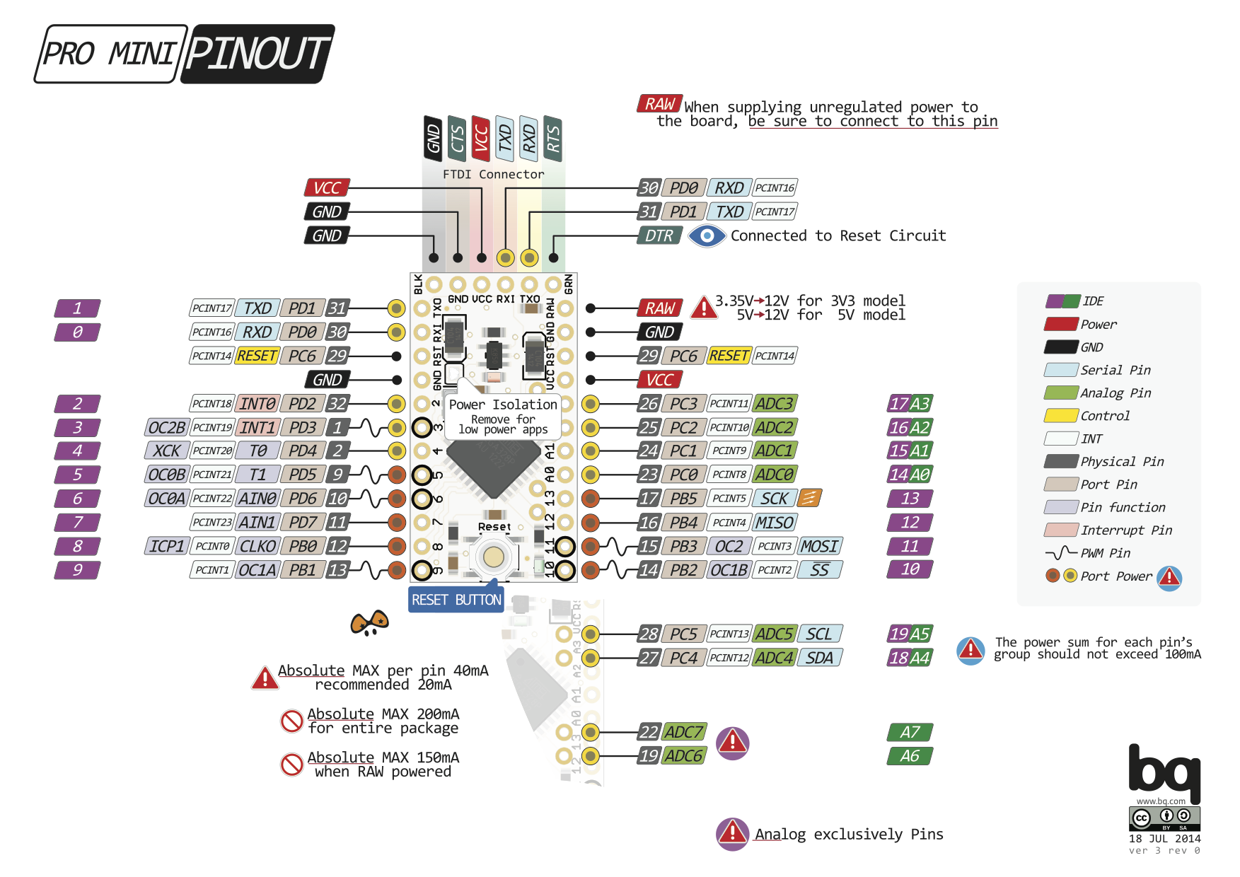
http://www.mysensors.org/build/pulse_power/** * The MySensors Arduino library handles the wireless radio link and protocol * between your home built sensors/actuators and HA controller of choice. * The sensors forms a self healing radio network with optional repeaters. Each * repeater and gateway builds a routing tables in EEPROM which keeps track of the * network topology allowing messages to be routed to nodes. * * Created by Henrik Ekblad <henrik.ekblad@mysensors.org> * Copyright (C) 2013-2015 Sensnology AB * Full contributor list: https://github.com/mysensors/Arduino/graphs/contributors * * Documentation: http://www.mysensors.org * Support Forum: http://forum.mysensors.org * * This program is free software; you can redistribute it and/or * modify it under the terms of the GNU General Public License * version 2 as published by the Free Software Foundation. * ******************************* * * REVISION HISTORY * Version 1.0 - Henrik EKblad * * DESCRIPTION * This sketch provides an example how to implement a distance sensor using HC-SR04 * Use this sensor to measure KWH and Watt of your house meeter * You need to set the correct pulsefactor of your meeter (blinks per KWH). * The sensor starts by fetching current KWH value from gateway. * Reports both KWH and Watt back to gateway. * * Unfortunately millis() won't increment when the Arduino is in * sleepmode. So we cannot make this sensor sleep if we also want * to calculate/report watt-number. * http://www.mysensors.org/build/pulse_power */ #include <SPI.h> #include <MySensor.h> #define DIGITAL_INPUT_SENSOR 3 // The digital input you attached your light sensor. (Only 2 and 3 generates interrupt!) #define PULSE_FACTOR 1000 // Nummber of blinks per KWH of your meeter #define SLEEP_MODE false // Watt-value can only be reported when sleep mode is false. #define MAX_WATT 10000 // Max watt value to report. This filetrs outliers. #define INTERRUPT DIGITAL_INPUT_SENSOR-2 // Usually the interrupt = pin -2 (on uno/nano anyway) #define CHILD_ID 4 // Id of the sensor child unsigned long SEND_FREQUENCY = 20000; // Minimum time between send (in milliseconds). We don't wnat to spam the gateway. MySensor gw; double ppwh = ((double)PULSE_FACTOR)/1000; // Pulses per watt hour boolean pcReceived = false; volatile unsigned long pulseCount = 0; volatile unsigned long lastBlink = 0; volatile unsigned long watt = 0; unsigned long oldPulseCount = 0; unsigned long oldWatt = 0; double oldKwh; unsigned long lastSend; MyMessage wattMsg(CHILD_ID,V_WATT); MyMessage kwhMsg(CHILD_ID,V_KWH); MyMessage pcMsg(CHILD_ID,V_VAR1); void setup() { gw.begin(incomingMessage); // Send the sketch version information to the gateway and Controller gw.sendSketchInfo("Energy Meter", "1.0"); // Register this device as power sensor gw.present(CHILD_ID, S_POWER); // Fetch last known pulse count value from gw gw.request(CHILD_ID, V_VAR1); attachInterrupt(INTERRUPT, onPulse, RISING); lastSend=millis(); } void loop() { gw.process(); unsigned long now = millis(); // Only send values at a maximum frequency or woken up from sleep bool sendTime = now - lastSend > SEND_FREQUENCY; if (pcReceived && (SLEEP_MODE || sendTime)) { // New watt value has been calculated if (!SLEEP_MODE && watt != oldWatt) { // Check that we dont get unresonable large watt value. // could hapen when long wraps or false interrupt triggered if (watt<((unsigned long)MAX_WATT)) { gw.send(wattMsg.set(watt)); // Send watt value to gw } Serial.print("Watt:"); Serial.println(watt); oldWatt = watt; } // Pulse cout has changed if (pulseCount != oldPulseCount) { gw.send(pcMsg.set(pulseCount)); // Send pulse count value to gw double kwh = ((double)pulseCount/((double)PULSE_FACTOR)); oldPulseCount = pulseCount; if (kwh != oldKwh) { gw.send(kwhMsg.set(kwh, 4)); // Send kwh value to gw oldKwh = kwh; } } lastSend = now; } else if (sendTime && !pcReceived) { // No count received. Try requesting it again gw.request(CHILD_ID, V_VAR1); lastSend=now; } if (SLEEP_MODE) { gw.sleep(SEND_FREQUENCY); } } void incomingMessage(const MyMessage &message) { if (message.type==V_VAR1) { pulseCount = oldPulseCount = message.getLong(); Serial.print("Received last pulse count from gw:"); Serial.println(pulseCount); pcReceived = true; } } void onPulse() { if (!SLEEP_MODE) { unsigned long newBlink = micros(); unsigned long interval = newBlink-lastBlink; if (interval<10000L) { // Sometimes we get interrupt on RISING return; } watt = (3600000000.0 /interval) / ppwh; lastBlink = newBlink; } pulseCount++; }The LED has the following diagram:
LED (RJ45) Sensebender
Pin 2 = VCC -> VCC
Pin 5 = GND -> GND
Pin 6 = IRQ1 -> D3 -
Thanks for your reply.
I took the sketch here:
http://www.mysensors.org/build/pulse_power/** * The MySensors Arduino library handles the wireless radio link and protocol * between your home built sensors/actuators and HA controller of choice. * The sensors forms a self healing radio network with optional repeaters. Each * repeater and gateway builds a routing tables in EEPROM which keeps track of the * network topology allowing messages to be routed to nodes. * * Created by Henrik Ekblad <henrik.ekblad@mysensors.org> * Copyright (C) 2013-2015 Sensnology AB * Full contributor list: https://github.com/mysensors/Arduino/graphs/contributors * * Documentation: http://www.mysensors.org * Support Forum: http://forum.mysensors.org * * This program is free software; you can redistribute it and/or * modify it under the terms of the GNU General Public License * version 2 as published by the Free Software Foundation. * ******************************* * * REVISION HISTORY * Version 1.0 - Henrik EKblad * * DESCRIPTION * This sketch provides an example how to implement a distance sensor using HC-SR04 * Use this sensor to measure KWH and Watt of your house meeter * You need to set the correct pulsefactor of your meeter (blinks per KWH). * The sensor starts by fetching current KWH value from gateway. * Reports both KWH and Watt back to gateway. * * Unfortunately millis() won't increment when the Arduino is in * sleepmode. So we cannot make this sensor sleep if we also want * to calculate/report watt-number. * http://www.mysensors.org/build/pulse_power */ #include <SPI.h> #include <MySensor.h> #define DIGITAL_INPUT_SENSOR 3 // The digital input you attached your light sensor. (Only 2 and 3 generates interrupt!) #define PULSE_FACTOR 1000 // Nummber of blinks per KWH of your meeter #define SLEEP_MODE false // Watt-value can only be reported when sleep mode is false. #define MAX_WATT 10000 // Max watt value to report. This filetrs outliers. #define INTERRUPT DIGITAL_INPUT_SENSOR-2 // Usually the interrupt = pin -2 (on uno/nano anyway) #define CHILD_ID 4 // Id of the sensor child unsigned long SEND_FREQUENCY = 20000; // Minimum time between send (in milliseconds). We don't wnat to spam the gateway. MySensor gw; double ppwh = ((double)PULSE_FACTOR)/1000; // Pulses per watt hour boolean pcReceived = false; volatile unsigned long pulseCount = 0; volatile unsigned long lastBlink = 0; volatile unsigned long watt = 0; unsigned long oldPulseCount = 0; unsigned long oldWatt = 0; double oldKwh; unsigned long lastSend; MyMessage wattMsg(CHILD_ID,V_WATT); MyMessage kwhMsg(CHILD_ID,V_KWH); MyMessage pcMsg(CHILD_ID,V_VAR1); void setup() { gw.begin(incomingMessage); // Send the sketch version information to the gateway and Controller gw.sendSketchInfo("Energy Meter", "1.0"); // Register this device as power sensor gw.present(CHILD_ID, S_POWER); // Fetch last known pulse count value from gw gw.request(CHILD_ID, V_VAR1); attachInterrupt(INTERRUPT, onPulse, RISING); lastSend=millis(); } void loop() { gw.process(); unsigned long now = millis(); // Only send values at a maximum frequency or woken up from sleep bool sendTime = now - lastSend > SEND_FREQUENCY; if (pcReceived && (SLEEP_MODE || sendTime)) { // New watt value has been calculated if (!SLEEP_MODE && watt != oldWatt) { // Check that we dont get unresonable large watt value. // could hapen when long wraps or false interrupt triggered if (watt<((unsigned long)MAX_WATT)) { gw.send(wattMsg.set(watt)); // Send watt value to gw } Serial.print("Watt:"); Serial.println(watt); oldWatt = watt; } // Pulse cout has changed if (pulseCount != oldPulseCount) { gw.send(pcMsg.set(pulseCount)); // Send pulse count value to gw double kwh = ((double)pulseCount/((double)PULSE_FACTOR)); oldPulseCount = pulseCount; if (kwh != oldKwh) { gw.send(kwhMsg.set(kwh, 4)); // Send kwh value to gw oldKwh = kwh; } } lastSend = now; } else if (sendTime && !pcReceived) { // No count received. Try requesting it again gw.request(CHILD_ID, V_VAR1); lastSend=now; } if (SLEEP_MODE) { gw.sleep(SEND_FREQUENCY); } } void incomingMessage(const MyMessage &message) { if (message.type==V_VAR1) { pulseCount = oldPulseCount = message.getLong(); Serial.print("Received last pulse count from gw:"); Serial.println(pulseCount); pcReceived = true; } } void onPulse() { if (!SLEEP_MODE) { unsigned long newBlink = micros(); unsigned long interval = newBlink-lastBlink; if (interval<10000L) { // Sometimes we get interrupt on RISING return; } watt = (3600000000.0 /interval) / ppwh; lastBlink = newBlink; } pulseCount++; }The LED has the following diagram:
LED (RJ45) Sensebender
Pin 2 = VCC -> VCC
Pin 5 = GND -> GND
Pin 6 = IRQ1 -> D3 -
Thanks.
The pulse sensor has got a separate green LED to indicate when a pulse is received - it is not blinking in my case. PrintIn does not show much unfortunately though the sensor is powered up with 3.3V. I need to figure out the pull-up/down resistor value. -
Thanks.
The pulse sensor has got a separate green LED to indicate when a pulse is received - it is not blinking in my case. PrintIn does not show much unfortunately though the sensor is powered up with 3.3V. I need to figure out the pull-up/down resistor value.@alexsh1 Not sure if you need an extra resistor. I would expect there is some internal circuitry in the sensor already. Have you looked at the schematics of the emonPi, etc. on the OpenEnergyMonitor website to see if they have any additional components on their input for the sensor? I would expect the led to flash if you have Vcc and Gnd connected so perhaps something else is wrong. Are you powering with 3.3v or 5v?
Cheers
Al -
@Sparkman Yes, I did look at the openenergymonitor wiki - does not say much.
http://openenergymonitor.org/emon/buildingblocks/opticalpulsesensorHowever, managed to find on the their web-site the following:
LED Pulse counting
No pull down resistor is required as the pulse / light sensor output is logic level 0 when the pulse is low. However, if you build a pulse counting module with pull down resistors of ~10k it still works with the light sensor, more info to come on this.
As this is sensebender (powered by two AA batteries), voltage is around 3.1V currently. Are you thinking this is an issue? Will check all the connections to make sure I do not have a bad connection or something.
-
@Sparkman I narrowed down the problem. The sketch and the sensor do not work with the sensebender. I used Arduino Nano instead and it worked though the gateway stopped receiving the signal after 10-20 mins, but that is a different problem. Now I think there is an issue with interruption with the sensebender.
Did anyone compiled energy pulse sensor on the sensebender please?
Hello! It looks like you're interested in this conversation, but you don't have an account yet.
Getting fed up of having to scroll through the same posts each visit? When you register for an account, you'll always come back to exactly where you were before, and choose to be notified of new replies (either via email, or push notification). You'll also be able to save bookmarks and upvote posts to show your appreciation to other community members.
With your input, this post could be even better 💗
Register Login