nRF5 action!


  • @NeverDie Is this the board with a PA on it or stand alone nRF5x part? If with a PA what is the rated voltage of the device?

    Depending on the Nordic part the nRF5x can run from 1.7 (or 1.8) to 3.6vdc. Note that the nRF51 cannot run with the DC / DC under 2vdc. The nRF52 does not have that restriction and the DC/DC can be used throughout the full voltage range..


  • Hero Member

    @Jokgi said in nRF5 Bluetooth action!:

    Is this the board with a PA on it or stand alone nRF5x part?

    I observed it on Ebyte's E73-2G4M04S on this board: https://www.openhardware.io/view/471/Ebyte-nRF52832-Small-Breakout-Board
    while running in DCDC mode. The E73-2G4M04 has no PA.

    For now, I'm just reporting the finding, in case anyone else has noticed it. Also, it's a very early result. If there's no known reason to suspect the nRF52832 as a possible cause (i.e. no erratas or the like), then I'm glad to hear it.


  • Hero Member

    OK, I fixed the problem by increasing the size of the listen window by another 30 microseconds (which is the smallest granularity that the RTC offers). What this probably means is that some aspect of the wake-up process (for instance, perhaps the amount of time it takes for the high frequency oscillator to come up to speed) is taking a wee bit longer when the module is powered at the lower voltage than when it is powered at 3.3v.


  • Hero Member

    @Jokgi said in nRF5 Bluetooth action!:

    @NeverDie Hello, If you are referring to that Prototype Board with the Nordic logo on it then it was being controlled by GPIO and by the Bluetooth Low Energy stack (Softdevice) You can read more about it here.. https://devzone.nordicsemi.com/blogs/831/palna-support-in-s132/.
    As I mentioned before. there is no good way to control the PA in a proprietary mode, only when using BLE. Regardless, I have asked if it is ok to share the schematic that relates to that PA board and I will let you all know. And about the question about antenna switching. This was never implemented in the Softdevice. Any antenna switching would need to be done in the application.
    See if this chart helps.

    0_1508212131505_I-O for nRF52832 - RFX2411n.JPG

    The only definition I've found for PDET is "Analog Voltage Proportional to the PA Power Output ." I'm not sure what that means. So, I set P0.02 to HIGH, which in this instance is 3.3v. However, I'm only getting relatively weak Tx power emitted. Is there anything else I should be doing? For instance, should I be supplying external voltage to the PDET pin directly?

    Here's the code I'm currently using to setup for transmission:

      myNrf5_pinMode(2,OUTPUT_H0H1); //PDET
      myNrf5_pinMode(20,OUTPUT_H0H1); //SWANT
      myNrf5_pinMode(24,OUTPUT_H0H1); //TXEN   
      myNrf5_pinMode(23,OUTPUT_H0H1); //RXEN
      myNrf5_pinMode(22,OUTPUT_H0H1); //MODE
    
      digitalWrite(20,HIGH);  //select one of the antenna's.
      digitalWrite(23,LOW);  //disable RXEN
      digitalWrite(24,HIGH);  //enable TXEN
      digitalWrite(22,LOW);  //disable MODE
      digitalWrite(2,HIGH);  //set the analog voltage for PDET as high as possible
    

  • Hero Member

    @NeverDie said in nRF5 Bluetooth action!:

    For instance, should I be supplying external voltage to the PDET pin directly?

    I tried that just now, and it made no difference.

    I also tried powering the PA_VDD pin externally at 3.3v, and that didn't help either. Does that pin expect higher voltages?


  • Hero Member

    @Jokgi said in nRF5 Bluetooth action!:

    @NeverDie 0_1508367805179_RD-nRF52-RFX2411N-REV2.zip Hello All -- For your viewing enjoyment. The Schematic and layout files for that nRF52840 and RFX2411n board you have. (If it is version 2 which did have the big Nordic logo on it. )
    I think you may know this already but this bears repeating. This is not a Nordic board. Nordic Semiconductor's tech support will probably not know anything about this board. Also there is a difference between the RFX2411 and the nRF2411N. (N for Nordic) It is not the same device.

    Just now noticed that the schematic explains PDET. It's "Optional Antenna Power Monitoring." So, I take that to mean that it's output from the board, not input to it.

    Also, the schematic indicates that the board has the DCDC inductors built into it, so that's good.


  • Hero Member

    Aha! Apparently the RFaxis defaults not to the trace antenna on the board, but rather to the external, connected antenna. So, I hooked that up, and now it's working like a champ. I can now safely say that it definitely has a much better range than a non-PA nRF52832 module. And, of course, I'm running it at 2mbps. 🙂

    The other nice thing is that even if I transmit continuously (i.e. 100% duty Tx cycle), the chips don't get hot. I'm impressed. I tried doing that with a LoRa module once, and it got too hot to even touch.

    It will be fun to check the range when there's a PA+LNA nRF52832 on both ends of the link.


  • Hero Member

    And here it is:
    0_1508440744687_RFaxis3.jpg


  • Hero Member

    Of course, I couldn't stop until I tried hooking it up to the 4w boost amplifier:
    0_1508445375879_RFaxis4.jpg
    Wow! That really kicks tail. I don't think there's a nook or cranny anywhere that I don't get a great signal now, and all from a single gateway. 🙂


  • Hero Member

    I just now ordered a number of Fanstel modules to go with the breakout boards I recently posted. It's worth noting that Fanstel's lowest cost nRF52832 module is only $3.75, which is lower than the Ebyte module: http://www.fanstel.com/buy/bt832-ble42-hardware-ready-for-bluetooth-5-module-2fhya
    I ordered one, and I'll see how it compares in actual use.


  • Hardware Contributor

    @NeverDie said in nRF5 Bluetooth action!:

    It's worth noting that Fanstel's lowest cost nRF52832 module is only $3.75, which is lower than the Ebyte module: http://www.fanstel.com/buy/bt832-ble42-hardware-ready-for-bluetooth-5-module-2fhya

    interesting for US customers only I think. Because last time I looked, shipping were too expensive (plus add extra shipping fee like customs etc.).


  • Hardware Contributor

    @NeverDie said in nRF5 Bluetooth action!:

    It's worth noting that Fanstel's lowest cost nRF52832 module is only $3.75, which is lower than the Ebyte module: http://www.fanstel.com/buy/bt832-ble42-hardware-ready-for-bluetooth-5-module-2fhya
    I ordered one, and I'll see how it compares in actual use.
    It's woth noting that despite it's "832" name it's in fact an nrf52810 😛

    @scalz said in nRF5 Bluetooth action!:

    interesting for US customers only I think. Because last time I looked, shipping were too expensive (plus add extra shipping fee like customs etc.).
    43$ shipping if you're not in the US. And with DHL meaning (at least for me) 10 extra dollars of DHL fee for custom processing + highest tax possible.


  • Hero Member


  • Hero Member

    It's too bad Fanstel's shipping rates outside the US are high. I received the modules I ordered from Fanstel in just a couple of days. I'll try them out after I receive the PCB's from OSH PARK, which should happen in about another 1-2 weeks. The pinout for Fanstel's "micro" version (BC832) is different, and obviously the land pattern is much smaller, so I just now did a separate breakout board for it and sent it to the fab.

    I'm trying to think now as to whether I'll have any future need for nRF24L01's. The very small and cheap nRF51822 seems to supplant it now with its 4dbm higher Tx power, and the nRF52 affords lower current consumption while in Tx or Rx, because of its DCDC option.


  • Hero Member

    @d00616 Is it still the case that we're limited to a single interrupt? For instance, I'd like to put the nRF52832 to wake-up periodically as a heartbeat where it reports its battery level, and I also want it to wake-up if a particular pin goes HIGH (e.g. if a PIR sensor is triggered). Presently I'm using the RTC to provide the one interrupt, and I use the PPI to create an RTC interrupt if it detects that the PIR sensor pin has gone HIGH. Then the interrupt code must determine the true cause of the interrupt. It would be cleaner if I could separate them into separate interrupts. This is just a simple example to explain what I mean by the question.


  • @NeverDie said in nRF5 Bluetooth action!:

    It's too bad Fanstel's shipping rates outside the US are high

    No issue for me as I am a using a mail forwarder(s) and I can highly recommend them to others. Bringing nrf52Dk from Arrow to Russia costed me $10 (inter-US shipping is free at Arrow).
    I am considering switching to Fanstel modules completely, especially to their PA+LNA ones


  • Contest Winner

    @NeverDie said in nRF5 Bluetooth action!:

    @d00616 Is it still the case that we're limited to a single interrupt? For instance, I'd like to put the nRF52832 to wake-up periodically as a heartbeat where it reports its battery level, and I also want it to wake-up if a particular pin goes HIGH (e.g. if a PIR sensor is triggered). Presently I'm using the RTC to provide the one interrupt, and I use the PPI to create an RTC interrupt if it detects that the PIR sensor pin has gone HIGH. Then the interrupt code must determine the true cause of the interrupt. It would be cleaner if I could separate them into separate interrupts.

    You can wake up the MCU via:

    • GPIO pin sense; used for sleep()
    • GPIOTE; consumes less engergy but pin must be dedected in software (0.1µA-0.5µA)
    • LPCOMP (0.5µA)
    • QDEC (5µA)

    The interrupts for LPCOMP and QDEC are not allocated by the arduino-port. I think the LPCOMP is a good point to start with.


  • Hardware Contributor

    @Toyman said in nRF5 Bluetooth action!:

    Bringing nrf52Dk from Arrow to Russia costed me $10 (inter-US shipping is free at Arrow).

    Do they ask you for shipment fee directly to Russia ?
    I'm in Vietnam and bringing nrf52DK from Arrow was free, like everything I order from them, and over US$20 it's even express shipment (By the way they have a 25% flash sale right now !)

    I'm interested on info on your mail forwarder if it's not only for Russia.


  • @Nca78 Arrow ships free to Russia, but only to companies, not to direct consumers this is linked to the fact they use couriers (DHL/Fedex) and not vanilla USPS.
    Have a look at www.shipito.com, it's not the one I am currently using, but Shipito works with the whole world. Pricing might be a bit steep, but I haven't looked at it for a long time.


  • http://blog.nordicsemi.com/getconnected/power-consumption-explained?utm_campaign=Blog update notifications&utm_source=hs_email&utm_medium=email&utm_content=57717514&hsenc=p2ANqtz-9HxcPCGqL9z_8UZBj38TZu8vg-vE-JmEgmzOlt-uiiGj32PO4Vm0brgVaCxtEly5tGV5aioj1vJezIbGK-xZVXV6zxQ&_hsmi=57717514


  • Had the nrf52dk shipped from arrow to the Netherlands. Because it was above 22 euro( something like that) DHL had to let it apply tax and some administration cost.

    The board costed 28 euro(inc shipping). The tax office estimate was that is was around 120 euro??? so they charged me a little to much. I filled in some forms to get some of the taxes back.

    When the board arrived I had to pay DHL 43 euro . So getting it though customes cost more than the board itself. 😏


  • Hardware Contributor

    @Omemanti said in nRF5 Bluetooth action!:

    When the board arrived I had to pay DHL 43 euro .
    DHL is selling it's shipment service cheaper to shops so the cost seems interesting for buyer. But their trick is to force you to pay some "service fee" when you receive your parcel in addition to custom taxes. This is borderline scam IMHO as this fee is mandatory and has a fixed value for each destination country, so DHL should include it upfront when customer orders.
    No more DHL shipment for me.


  • Hero Member

    @d00616 said in nRF5 Bluetooth action!:

    @NeverDie said in nRF5 Bluetooth action!:

    @d00616 Is it still the case that we're limited to a single interrupt?  For instance, I'd like to put the nRF52832 to wake-up periodically as a heartbeat where it reports its battery level, and I also want it to wake-up if a particular pin goes HIGH (e.g. if a PIR sensor is triggered).  Presently I'm using the RTC to provide the one interrupt, and I use the PPI to create an RTC interrupt if it detects that the PIR sensor pin has gone HIGH.  Then the interrupt code must determine the true cause of the interrupt.  It would be cleaner if I could separate them into separate interrupts. 
    

    You can wake up the MCU via:

    • GPIO pin sense; used for sleep()
    • GPIOTE; consumes less engergy but pin must be dedected in software (0.1µA-0.5µA)
    • LPCOMP (0.5µA)
    • QDEC (5µA)

    The interrupts for LPCOMP and QDEC are not allocated by the arduino-port. I think the LPCOMP is a good point to start with.

    I have it now where LPCOMP does detect pin AIN1 (i.e. pin P0.03) going HIGH, but it still doesn't wake-up the MCU, and the interrupt code never runs. I could use the PPI to trigger an RTC interrupt when it detects the NRF_LPCOMP->EVENTS_UP event, which would wake up the MCU, but then I'm back to square one. Is that the best that can be done given the current state of the software?

    #define MY_CORE_ONLY
    
    #include <nrf.h>
    #include <MySensors.h>
    
    uint32_t blinkCounter=0;
    uint32_t interruptCounter=0;
    bool button_pressed=false;
    
    void setup() {
      Serial.begin(9600);
      Serial.println();
      Serial.println("Starting...");
    
      // Enable interrupt
      NVIC_SetPriority(LPCOMP_IRQn, 15);
      NVIC_ClearPendingIRQ(LPCOMP_IRQn);
      NVIC_EnableIRQ(LPCOMP_IRQn);
    
      hwPinMode(LED_BUILTIN,OUTPUT_H0H1);
      //hwPinMode(PIN_BUTTON1,INPUT);
      NRF_LPCOMP->PSEL=1; // monitor AIN1 (pin P0.03).
      while (!(NRF_LPCOMP->PSEL==1)) {} //wait until confirmed
      NRF_LPCOMP->REFSEL=3;  // choose 1/2 VDD as the reference voltage
      while (!(NRF_LPCOMP->REFSEL==3)) {} //wait until confirmed
      NRF_LPCOMP->INTENSET=B0100;  //Enable interrupt for UP event
      while (!(NRF_LPCOMP->INTENSET==B0100)) {} //wait until confirmed
      NRF_LPCOMP->ENABLE=1;  //Enable LPCOMP
      while (!(NRF_LPCOMP->ENABLE==1)) {} //wait until confirmed
      NRF_LPCOMP->TASKS_START=1;  //start the LPCOMP
      while (!(NRF_LPCOMP->EVENTS_READY)) {}  //wait until ready
    }
    
    
    void loop() {
      Serial.print(blinkCounter++);
      Serial.println("HIGH");
      digitalWrite(LED_BUILTIN,HIGH);
      delay(20);
    
    /*
      if (NRF_LPCOMP->EVENTS_UP) {
        digitalWrite(LED_BUILTIN,HIGH);
        delay(2000);
        NRF_LPCOMP->EVENTS_UP=0;  //Clear the semaphore
      }
      */
    
      if (button_pressed) {
        digitalWrite(LED_BUILTIN,HIGH);
        delay(2000);
        button_pressed=false;  //Clear the semaphore
        NRF_LPCOMP->EVENTS_UP=0;  //Clear the semaphore
      }
      
      digitalWrite(LED_BUILTIN,LOW);
      hwSleep(5000);
    }
    
    
    // * Reset events and read back on nRF52
    //* http://infocenter.nordicsemi.com/pdf/nRF52_Series_Migration_v1.0.pdf
     
    #if __CORTEX_M == 0x04
    #define NRF5_RESET_EVENT(event)                                                 \
            event = 0;                                                                   \
            (void)event
    #else
    #define NRF5_RESET_EVENT(event) event = 0
    #endif
    
    
    // This must be in one line
    //extern "C" { void GPIO_IRQHandler(void) {interruptCounter++; NRF5_RESET_EVENT(NRF_RTC0->EVENTS_OVRFLW); NRF_RTC0->EVENTS_OVRFLW=0; }}
    extern "C" { void LPCOMP_IRQHandler(void) {button_pressed=true; interruptCounter++; NRF5_RESET_EVENT(NRF_LPCOMP->EVENTS_UP); NRF_LPCOMP->EVENTS_UP=0; }}
    

  • Hero Member

    Getting closer... The LPCOMP interrupt code does run, but the main loop doesn't resume until the RTC timer makes it resume because the programmed time interval has expired.

    I know this is true because if, during sleep, I make AIN1 go HIGH, and then LOW, then when the MCU later wakes up because of the RTC, it so indicates by making the LED go HIGH for 2 seconds. However, even though there's now solid proof that the LPCOMP interrupt hardware does execute, the main loop doesn't immediately resume, as it does when the RTC times out.

    So.... How to make the main loop immediately resume whenever LPCOMP goes UP?


  • Hero Member

    Well, I have to re-build the timer part of this, and clean up the code, but at least now a PIR sensor trigger will immediately wake-up the MCU. That's progress! Unfortunately, current drawn during sleep is now 456ua, which is much higher than it should be.

    #define MY_CORE_ONLY
    
    #include <nrf.h>
    #include <MySensors.h>
    
    uint32_t rtcInterruptCounter=0;
    uint32_t buttonPressInterruptCounter=0;
    bool button_pressed=false;
    
    
    void myHwSleepPrepare(unsigned long ms)
    {
      // Idle serial device
      NRF_UART0->TASKS_STOPRX = 1;
      NRF_UART0->TASKS_STOPTX = 1;
      NRF_UART0->TASKS_SUSPEND = 1;
      //NRF_UART0->ENABLE=0;  //disable UART0
    
      //NRF_CLOCK->TASKS_HFCLKSTOP = 1;
      
      // Enable low power sleep mode
      NRF_POWER->TASKS_LOWPWR = 1;
    
    }
    
    // Sleep in System ON mode
    inline void doTheSleep()
    {
      __WFE();
      __SEV();
      __WFE();
    }
    
    void myHwSleepEnd(unsigned long ms)
    {
      // Start HFCLK
      //if (nrf5_pwr_hfclk) {
      if (false) {
        NRF_CLOCK->EVENTS_HFCLKSTARTED = 0;
        NRF_CLOCK->TASKS_HFCLKSTART = 1;
        while (NRF_CLOCK->EVENTS_HFCLKSTARTED == 0)
          ;
        // Enable low latency sleep mode
        //NRF_POWER->TASKS_CONSTLAT = 1;
      }
    }
     
    void myHwSleep(unsigned long ms)
    {
      myHwSleepPrepare(ms);
      doTheSleep();
      //now sleeping
      myHwSleepEnd(ms);
    
    }
    
    
    void setup() {
      //Serial.begin(9600);
      //Serial.println();
      //Serial.println("Starting...");
    
      
        // Enable interrupt
      NVIC_SetPriority(LPCOMP_IRQn, 15);
      NVIC_ClearPendingIRQ(LPCOMP_IRQn);
      NVIC_EnableIRQ(LPCOMP_IRQn);
      
      hwPinMode(LED_BUILTIN,OUTPUT_H0H1);
      //hwPinMode(PIN_BUTTON1,INPUT);
      NRF_LPCOMP->PSEL=1; // monitor AIN1 (pin P0.03).
      while (!(NRF_LPCOMP->PSEL==1)) {} //wait until confirmed
      NRF_LPCOMP->REFSEL=3;  // choose 1/2 VDD as the reference voltage
      while (!(NRF_LPCOMP->REFSEL==3)) {} //wait until confirmed
      NRF_LPCOMP->INTENSET=B0100;  //Enable interrupt for UP event
      while (!(NRF_LPCOMP->INTENSET==B0100)) {} //wait until confirmed
      NRF_LPCOMP->ENABLE=1;  //Enable LPCOMP
      while (!(NRF_LPCOMP->ENABLE==1)) {} //wait until confirmed
      NRF_LPCOMP->TASKS_START=1;  //start the LPCOMP
      while (!(NRF_LPCOMP->EVENTS_READY)) {}  //wait until ready
    
      //NRF_PPI->CH[0].EEP = (uint32_t)&NRF_LPCOMP->EVENTS_UP;  //If PIR sensor is triggered
      //NRF_PPI->CH[0].TEP = (uint32_t)&NRF_RTC0->TASKS_TRIGOVRFLW;  //make the RTC wake-up the MCU
    
      //NRF_PPI->CHENSET=B00000001; //enable Channel 0.
      
      NRF_RTC0->INTENSET = B10;  //interrupt MCU if an OVRFLW is detected.
      while (NRF_RTC0->INTENSET != B10) {}  //wait until confirmed
    
    }
    
    
    void loop() {
      //Serial.print(blinkCounter++);
      //Serial.println("HIGH");
      digitalWrite(LED_BUILTIN,HIGH);
      delay(20);
    
    /*
      if (NRF_LPCOMP->EVENTS_UP) {
        digitalWrite(LED_BUILTIN,HIGH);
        delay(2000);
        NRF_LPCOMP->EVENTS_UP=0;  //Clear the semaphore
      }
      */
    
      if (button_pressed) {
        digitalWrite(LED_BUILTIN,HIGH);
        delay(2000);
        button_pressed=false;  //Clear the semaphore
        NRF_LPCOMP->EVENTS_UP=0;  //Clear the semaphore
      }
      
      digitalWrite(LED_BUILTIN,LOW);
      myHwSleep(5000);
    }
    
    
    // * Reset events and read back on nRF52
    //* http://infocenter.nordicsemi.com/pdf/nRF52_Series_Migration_v1.0.pdf
     
    #if __CORTEX_M == 0x04
    #define NRF5_RESET_EVENT(event)                                                 \
            event = 0;                                                                   \
            (void)event
    #else
    #define NRF5_RESET_EVENT(event) event = 0
    #endif
    
    
    // This must be in one line
    extern "C" { void RTC0_IRQHandler(void) {rtcInterruptCounter++; NRF5_RESET_EVENT(NRF_RTC0->EVENTS_OVRFLW); NRF_RTC0->EVENTS_OVRFLW=0; }}
    extern "C" { void LPCOMP_IRQHandler(void) {button_pressed=true; buttonPressInterruptCounter++; NRF5_RESET_EVENT(NRF_LPCOMP->EVENTS_UP); NRF_LPCOMP->EVENTS_UP=0; }}
    

  • Hero Member

    Aha! Most likely the high current draw is from the high frequency clock, which I need to turn off prior to sleep but haven't done yet.


  • Hero Member

    Anyhow, the basic question remains and boils down to this: Can I have both

        // Enable interrupt
      NVIC_SetPriority(LPCOMP_IRQn, 15);
      NVIC_ClearPendingIRQ(LPCOMP_IRQn);
      NVIC_EnableIRQ(LPCOMP_IRQn);
    

    AND an equivalent incantation for the RTC both active at the same time? Or am I forced into having it be just one or the other?


  • @NeverDie Did you manage to get more than 10m ? maybe by another modules.

    I thought the nrf52 will have better range !


  • @ahmedadelhosni
    Sure, I'm using a similar one.
    Why wouldn't it work? The nrf52 is an ARM Mx, like the ST chips. The programming interface is the same. You could also use one of the many other ARM programmers, like J-Link, or nearly any JTAG programmer supported by OpenOCD.

    Just follow this guide: https://www.openhardware.io/view/376/MySensors-NRF5-Platform
    And: https://github.com/sandeepmistry/arduino-nRF5/#installing


  • @Uhrheber Great. Thanks for the help.

    So if I understand well. If I have a TIVA board like TM4C123G Launchpad and it is ARM Mx also, then I can use it to program my nRF ?

    This is the datasheet for the board : http://www.ti.com/lit/ug/spmu296/spmu296.pdf

    I searched and found those links describing how to use the Launchad but I am not sure whether this will work for nRF also or not.

    http://processors.wiki.ti.com/index.php/Stellaris_LM4F120_LaunchPad_Debug_How_To
    http://ucsolutions.blogspot.com.eg/2014/08/ti-launchpad-as-external-debugger-with.html

    Thanks.


  • Hardware Contributor

    @ahmedadelhosni said in nRF5 Bluetooth action!:

    @Uhrheber Great. Thanks for the help.

    So if I understand well. If I have a TIVA board like TM4C123G Launchpad and it is ARM Mx also, then I can use it to program my nRF ?

    This is the datasheet for the board : http://www.ti.com/lit/ug/spmu296/spmu296.pdf

    I searched and found those links describing how to use the Launchad but I am not sure whether this will work for nRF also or not.

    http://processors.wiki.ti.com/index.php/Stellaris_LM4F120_LaunchPad_Debug_How_To
    http://ucsolutions.blogspot.com.eg/2014/08/ti-launchpad-as-external-debugger-with.html

    Thanks.

    I think it's a question of the licence of the programmer that is on your board.
    For example the J-Link version on the NRF52 DK is only allowed to program NRF52 and NRF51 chips. It's logic because the NRF52DK is just over 30$ while a J-Link programmer is x00$.
    You have pins SWDIO and SWDCLK on pins PC0 and PC1 of your board so just try it and you will know 🙂


  • @Nca78 Yeah actually this makes sense. I forgot about the licence thing. Actually I didn't bug the boards and I want to get everything at once without missing anything. I am in a hurry 😄

    it is strange that this clone can do the work as @Uhrheber mentioned.

    http://s.click.aliexpress.com/deep_link.htm?dl_target_url=https%3A%2F%2Fwww.aliexpress.com%2Fitem%2FHot-Sale-1PCS-ST-LINK-Stlink-ST-Link-V2-Mini-STM8-STM32-Simulator-Download-Programmer-Programming%2F32343514985.html%3Fspm%3D2114.search0104.3.26.LR8eH0%26ws_ab_test%3Dsearchweb0_0&aff_short_key=e2Vzr3v


  • Guys, your best bet is to reflash STM32 Bluepill into BlackMagicProbe.
    It's awesome!
    https://medium.com/@paramaggarwal/converting-an-stm32f103-board-to-a-black-magic-probe-c013cf2cc38c


  • Hero Member

    @NeverDie said in nRF5 Bluetooth action!:

    Anyhow, the basic question remains and boils down to this: Can I have both

        // Enable interrupt
      NVIC_SetPriority(LPCOMP_IRQn, 15);
      NVIC_ClearPendingIRQ(LPCOMP_IRQn);
      NVIC_EnableIRQ(LPCOMP_IRQn);
    

    AND an equivalent incantation for the RTC both active at the same time? Or am I forced into having it be just one or the other?

    @d00616 Any thoughts or comments regarding this?


  • Contest Winner

    @NeverDie said in nRF5 Bluetooth action!:

    @d00616 Any thoughts or comments regarding this?

    Sorry, I can't help here. Maybe, the interrupt priority can be used only once and you have to use another priority for RTC or LPCOMP.


  • Hero Member

    I tried out the Fanstel BT832X (i.e. nRF52832 with PA and LNA) today:
    alt text

    Good news:

    1. Even without the PA turned on, the range seems a lot better than if transmitting from an Ebyte module.
    2. Also, I've confirmed that it comes with DCDC built-in.
    3. With the PA turned on, the range is comparable to, and perhaps even better than, the RFaxis I reviewed earlier in this thread.

    With the PA turned on, it consumes about 250ma.


  • Hero Member

    @d00616 I hooked up the Fanstel BT832A. Although it appeared to flash and verify correctly, I couldn't get it to do anything--not even blink. Is there any chance that it's downsized flash/memory has something to do with it? "Flash/RAM memories in BT832 are 512KB/64KB. They are 192KB/24KB in BT832A." So, as an experiment, I hooked up a BT832 in its place on the same board, and it's able to transmit and blink just fine. In total, the only differences between the two are:

    1. Cortex M4F in BT832 has hardware DSP and floating point instructions. Cortex M4 in BT832A has hardware DSP instructions but it does not have floating point unit to support hardware instruction.
    2. Flash/RAM memories in BT832 are 512KB/64KB. They are 192KB/24KB in BT832A.
    3. BT832 has NFC tag interface. BT832A does not have NFC tag
      interface.

    I think we can rule out #3. So, if it isn't #2, then is perhaps #1 a factor? I wouldn't think so.

    The solder connections seemed correct. I suppose it's possible I simply got a bad module, but I'm doubtful that's it.

    Here's a photo of it installed on a BT832X board, which is pin-for-pin compatible:
    0_1509216144568_BT832A.jpg


  • Contest Winner

    @NeverDie said in nRF5 Bluetooth action!:

    I think we can rule out #3. So, if it isn't #2, then is perhaps #1 a factor? I wouldn't think so.

    I think, you have to do more things:

    1. Change compiler attributes to disable FPU support
    2. Change the memory layout in linker scripts. Look into boards definition. Linker scripts are placed under ./cores/nRF5/SDK/components/toolchain/gcc/ The SDK14 has scripts supporting the nrf52810
    3. The SDK14 has an dedicated startup code (gcc_startup_nrf52810.S), I don't know if this relevant for arduino-nrf5

    I think there is more to do than compile the code. I think the SDK code for arduino-nrf5 must be updated to SDK 14, then a nre MCU must be defined.

    I have compared the startup code. The difference is in the interrupt vector. It should work with the NRF52832 startup code, but the linker script must be changed.


  • Hero Member

    @d00616 Also, at least so far, I haven't been able to get the Fanstel modules to receive anything. At first I thought it must be an LNA thing, but I tried it just now on a Fanstel module without LNA, and although it can transmit and blink just fine, the regular receive code isn't working. Any theories on that?
    0_1509217353206_BT832.jpg


  • Contest Winner

    @NeverDie said in nRF5 Bluetooth action!:

    @d00616 Also, at least so far, I haven't been able to get the Fanstel modules to receive anything. At first I thought it must be an LNA thing, but I tried it just now on a Fanstel module without LNA, and although it can transmit and blink just fine, the regular receive code isn't working. Any theories on that?

    I think this could be the memory layout -> linker script. My try to port Arduino to nrf51 in 2014 is failed at the same state. Blink was ok. Using something with memory are failed. The reason was a wrong linker script. At this time Nordic hasen't released (L)GPG compatible scripts.

    Edit: I think it's possible to add the 82810 to https://github.com/mysensors/ArduinoHwNRF5 by changing the board definition and add the missing linker script into the variant folder.


  • Hero Member


  • Hero Member

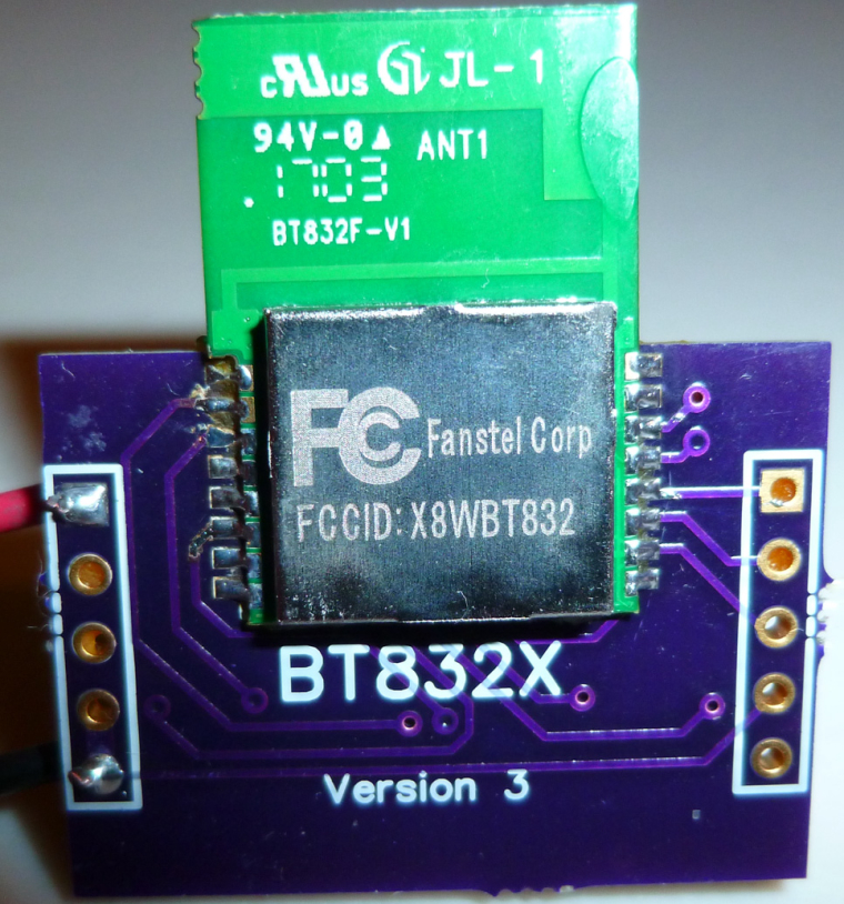
    OK, I need to confirm it, but I have a theory now that the Fanstel modules don't have 32K clock crystals in them. That would explain why that have pinouts for XTAL1 and XTAL2. It might also be hanging my code, which assumes there is a clock crystal and tries to turn it on. My using pin P0.02 to control the LED might be a deadly brew that causes the hang. I'll post a follow-up if that's what turns out to be the actual root of what superficially seemed like an "Rx problem."


  • Hero Member

    It's confirmed. Son of a gun, they don't have the 32K clock crystal on the module. On the datasheet, it says that for battery operation, "We suggest adding a 32.768 kHz crystal and 2 capacitors as shown in the upper left corner of the evaluation board schematics."

    I'll add pads for it on the breakout board.


  • Hero Member

    @NeverDie said in nRF5 Bluetooth action!:

    My using pin P0.02 to control the LED might be a deadly brew that causes the hang.

    Correction: Use of P0.02 to control the LED shouldn't be a problem, as it corresponds to AIN0 and isn't involved in XTAL. Therefore, I edited the original post to strike-through this sentence.


  • Hero Member

    Good news! Switching over to the RC oscillator totally fixed the problem. Both the Fanstel BT832 and BT832X now receive just fine. 🙂


  • Hero Member

    In fact, both the Fanstel BT832 and the BT832X (with no LNA turned on) have much better receive range than an Ebyte module. They are head and shoulders better. In turn the BT832X (again, even with no LNA turned on) has a noticeably better receive range than the BT832.

    So, at this point, I'm sold on the Fanstel modules for the most common uses. The Fanstel modules also have a smaller footprint than the Ebyte modules. The Ebyte modules might be better for those cases where you need a lot of easily accessible pins to do something, but that's about it I think.


  • Hardware Contributor

    @NeverDie said in nRF5 Bluetooth action!:

    In fact, both the Fanstel BT832 and the BT832X (with no LNA turned on) have much better receive range than an Ebyte module. They are head and shoulders better. In turn the BT832X (again, even with no LNA turned on) has a noticeably better receive range than the BT832.

    So, at this point, I'm sold on the Fanstel modules for the most common uses. The Fanstel modules also have a smaller footprint than the Ebyte modules. The Ebyte modules might be better for those cases where you need a lot of easily accessible pins to do something, but that's about it I think.

    Now we need to convince Fanstel to find another shipping method outside the US 😄


  • @NeverDie it looks like we found an ideal gateway.
    What about the code they provide to activate PA+LNA?
    Can it be used in mysensors?


  • Hero Member

    I tried out the sub-dime sized BC832 on a quick port of the BC832X breakout board:
    0_1509402087595_bc832.jpg

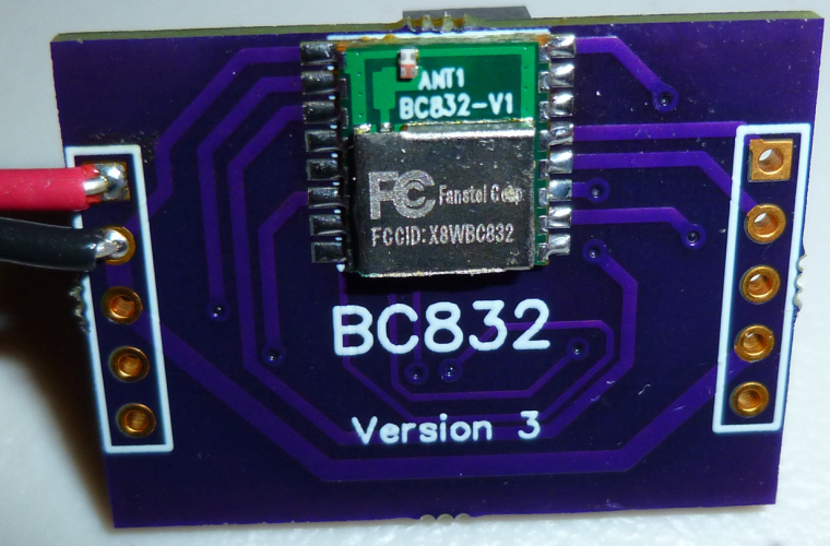
    What I'm finding is that the Rx range for the BC832 is about the same as for the Ebyte nRF52832 module: I'm hard pressed to tell which is better than the other. The BC832 is nonetheless impressive, given how small its antenna is relative to the Ebyte antenna.


  • Hero Member

    @Toyman said in nRF5 Bluetooth action!:

    it looks like we found an ideal gateway.

    Agreed. 🙂

    @Toyman said in nRF5 Bluetooth action!:

    What about the code they provide to activate PA+LNA?

    I only extracted the needed info from their code to make it work. It works just fine with mysensors. For instance, here's mysensors code to activate the PA:

    #define PA_PIN 17
    #define CPS_PIN 6
    #define LNA_PIN 19 
    
      myNrf5_pinMode(CPS_PIN,OUTPUT_H0H1);
      digitalWrite(CPS_PIN,HIGH);  //disable.  Active LOW
      //while (!(digitalRead(CPS_PIN)==HIGH)) {} //wait until confirmed
       
      myNrf5_pinMode(LNA_PIN,OUTPUT_H0H1);
      digitalWrite(PA_PIN,LOW);  //disable.  active HIGH
      //while (!(digitalRead(LNA_PIN)==LOW)) {} //wait until confirmed
      
      myNrf5_pinMode(PA_PIN,OUTPUT_H0H1);  
      digitalWrite(PA_PIN,HIGH);  //enable.  active HIGH
      //while (!(digitalRead(PA_PIN)==HIGH)) {} //wait until confirmed
    
      //myNrf5_pinMode(CPS_PIN,OUTPUT_H0H1);  
      digitalWrite(CPS_PIN,LOW);  //enable.  active LOW
      //while (!(digitalRead(CPS_PIN)==LOW)) {} //wait until confirmed
    

    I've tested it, and it works. From my testing it appears that the pins are write-only (which is why the while loops are now commented out).


  • @Nca78 How about sending a email to the company and ask if there is a distributor / Rep in your area?
    Dr. Yuan Fan
    Fanstel Corp.
    Trusted Name Since 1990
    7466 E. Monte Cristo Ave., Scottsdale AZ 85260 USA
    Tel. 1480-948-4928 x101;
    email: yfan@fanstel.com http://www.fanstel.com


  • Hero Member


  • Hero Member

    @Toyman Have you received your Fanstels yet? I'd like to compare notes with someone on the LNA part of it.


  • @NeverDie I haven't ordered yet. Waiting for my paycheck.


  • Hero Member

    When you combine my BT832XE gateway with the LNA on this external "booster," the result is really great reception range, even at 2Mbps:
    0_1509558101829_awesome.jpg
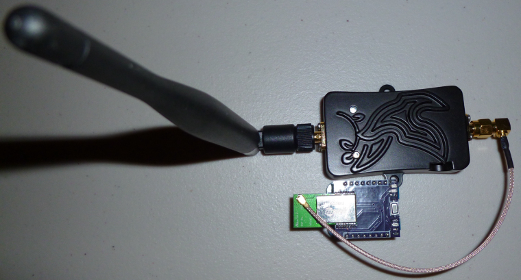
    I think this combo will be hard to beat. In fact, I can receive even from nRF24L01's that are far away (further away than a nRF24L01 with PA+LNA can receive). 🙂


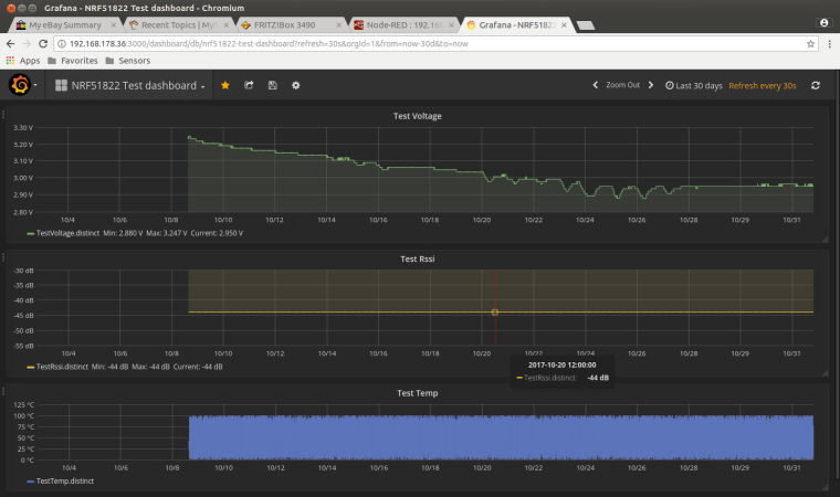
  • Well my NRF51822 has been running 25days approx sending every 60secs on a cr2032.
    No signs of problems yet.
    0_1509561715247_upload-e21e5fcc-113b-4d47-bd54-7d7d89841bf9


  • Hero Member

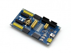
    @rmtucker I don't recall whether you already have, but would you mind posting a photo of your node?


  • @NeverDie
    Its just the waveshare ble400 board but i have cut one of the tracks to prevent the residual drain from the on board regulator.
    And i have an external cr2032 battery holder feeding it.
    I would love to make a small pcb for the NRF core to plug in to instead of the big motherboard as below, but i failed dismally at the design side of things.

    0_1509571898531_upload-00d6665f-f065-4ed7-927d-2a5e27224fc6


  • Hero Member

    @rmtucker said in nRF5 Bluetooth action!:

    I would love to make a small pcb for the NRF core to plug in to instead of the big motherboard as below

    Here you go: https://www.openhardware.io/view/510/Button-cell-Temperature-Humidity-sensor#tabs-bom

    This should be even smaller and less expensive than what you wished for. I made it for the Si7021 because I had some extras laying around. The BME280 would also be a good choice.


  • @NeverDie
    That would be perfect but i would have to order everything from china.
    Well maybe not the led and resistor.
    I also prefer the si7021 also it has far less consumption and quite accurate.


  • Hero Member

    @rmtucker said in nRF5 Bluetooth action!:

    I also prefer the si7021 also it has far less consumption and quite accurate

    As long as the humidity is less than 80%. Otherwise, you need to turn on its "heater" to avoid permanently ruining its humidity accuracy.


  • Hardware Contributor

    @NeverDie it's not that quick, it happened only to the one I put in bathroom with very high humidity for a long time.
    Other sensors reached over 90% humidity sometimes and spent many days in the 75-85 range but just a nightly use of aircon seems to have maintained their hability to measure humidity.
    So my feeling is unless you are in a very humid environment you should have no problem with the si7021.

    I'm in a tropical country and problem happened during rainy season, >80% humidity at 30°C makes a lot of humity in the air, I don't think you get close to that level in European countries or most of the US.


  • Hero Member

    @Nca78 I'm just taking what the datasheet says at face value. In practical terms, I think it's fairly rare to see >80% humidity in an indoor "conditioned space" (well, maybe a bathroom is an exception to that sweeping generality) but outdoors it happens by definition anytime the air temperature approaches the dew point. That certainly does occur in quite a lot of geographies.

    So, for that reason, I think of the si7021 as more of an indoor TH sensor. From what I can tell, the BME280 doesn't have this issue, so it would therefore seem to be a good choice for outdoors.

    Of course, the si7021 sensor modules are made in Asia, and if it's tropical asia (Thailand for instance?), it may have already been exposed to high humidity. So, that's a bit of an unknown factor hanging in the background.

    Anyhow, thanks for the additional insight that maybe the si7021 really needs to soak in high humidity for a long time before it gets ruined. Otherwise, it can spring back from brief exposures. I certainly hope that's the case. Running its heater does consume a significant amount of current.


  • Hero Member

    It turns out that on the nRF52832, pins 9 and 10 are assigned to NFC by default. The following code allows them to behave "almost" like regular GPIO pins:

      //Make pins 9 and 10 usable as GPIO pins.
      NRF_NFCT->TASKS_DISABLE=1;  //disable NFC
      NRF_NVMC->CONFIG=1;  // Write enable the UICR
      NRF_UICR->NFCPINS=0; //Make pins 9 and 10 usable as GPIO pins.
      NRF_NVMC->CONFIG=0;  // Put the UICR back into read-only mode.
    

    Well, good enough for a blink demo anyway.


  • Hero Member

    Is there some particular trick to reading the built-in temperature sensor? I've tried it a number of ways, but after doing

    NRF_TEMP->TASKS_START
    

    I can never get NRF_TEMP->DATARDY to return true, no matter how long I wait. If I just try reading NRF_TEMP->TEMP anyway, it always returns zero.

    [Edit: Nevermind. The answer was right in front of me. It obviously should have been:

    NRF_TEMP->TASKS_START=1;
    

    Because the PPI uses the former syntax, and the regular code uses the later syntax for the same thing, I sometimes interchange the syntax by mistake.

    Anyhow, problem solved. 🙂


  • @NeverDie said in nRF5 Bluetooth action!:

    BT832XE

    What booster is it?


  • Hero Member

    @NeverDie said in nRF5 Bluetooth action!:

    @rmtucker said in nRF5 Bluetooth action!:

    I would love to make a small pcb for the NRF core to plug in to instead of the big motherboard as below

    Here you go: https://www.openhardware.io/view/510/Button-cell-Temperature-Humidity-sensor#tabs-bom

    This should be even smaller and less expensive than what you wished for. I made it for the Si7021 because I had some extras laying around. The BME280 would also be a good choice.

    I'm realizing now that I can get a decent temperature reading from just the nRF5x chip itself. With calibration it should get even better.


  • Hero Member

    Today I finally received the PTR9618PA that I ordered a while back:
    0_1510110556809_ptr1.jpg
    0_1510110572062_ptr2.jpg

    Like the Fanstel modules, it lacks a 32.768Khz crystal oscillator. Also, as you can see from the second photo, the PA/LNA chip is the 2401C: http://www.skyworksinc.com/Product/3213/RFX2401C


  • @NeverDie said in nRF5 Bluetooth action!:

    @NeverDie said in nRF5 Bluetooth action!:

    I'm realizing now that I can get a decent temperature reading from just the nRF5x chip itself. With calibration it should get even better.

    I used the internal temperature in the past but i can not remember how i did it?
    Do you have some example code to remind me?


  • Hero Member

    @rmtucker said in nRF5 Bluetooth action!:

    Do you have some example code to remind me?

    /*
     * This example sketch shows how you can manage the nRF5 pin mapping as part of your code.
     * You can use the method for any nRF51822 or nRF52832 board or module.
     * 
     * Most components, like UART, SPI, Wire Bus, of the nRF5 series chips don't
     * have a fixed pin mapping. There are some pins with restrictions like analog
     * inputs, NFC or pins near the radio module. Please refer the latest
     * documentation about pin restrictions at http://infocenter.nordicsemi.com 
     * 
     * To use the custom pin mapping you have to do following steps:
     * 
     * 1. Install "arduino-nrf5" like described at
     *    https://github.com/sandeepmistry/arduino-nRF5/
     * 2. Install the "My Sensors nRF5 Boards" with the board manager like
     *    explained at https://github.com/mysensors/ArduinoBoards
     * 3. Copy the files "MyNRF5Board.cpp" and "MyNRF5Board.h" from
     *    "MyNRF5Board" example into your sketch.
     * 4. Modify pin mappings in "MyNRF5Board.cpp" and "MyNRF5Board.h" to fit
     *    your requirements.
     * 5. Select "MyNRF5Board nrf52832" or "MyNRF5Board nrf52822" as your board.
     *    Choose the correct parameters and programmer in the Tools menu.
     */
    
    // Many thanks to d00616 for this framework!
    
    //------------------------------------------------------------------------------------------------------------------------------------------------------------------------
    
    //Simple program to demonstrate that both the LED and Serial  and Temperature are working correctly on the breakout board:
    // https://www.openhardware.io/view/471/Ebyte-nRF52832-Small-Breakout-Board
    
    //Note: Compile and upload from Arduino IDE using "MyNRF5Board nRF51822" as the board and with 16K RAM, RC Oscillator, and no bootloader as the options.  
    //


    #define MY_CORE_ONLY
    
    #include <nrf.h>
    #include <MySensors.h>
    
    
    void setup() {
      hwPinMode(LED_BUILTIN,OUTPUT_D0H1);
      digitalWrite(LED_BUILTIN,HIGH);
      NRF_CLOCK->INTENSET=B11;  //enable interrupts for EVENTS_HFCLKSTARTED and  EVENTS_LFCLKSTARTED
      Serial.begin(9600);
      Serial.println();
      Serial.println("Starting...");
      NRF_CLOCK->TASKS_HFCLKSTART=1;  //start the high frequency crystal oscillator clock
      while (!(NRF_CLOCK->EVENTS_HFCLKSTARTED)) {} //wait until high frequency crystal oscillator clock is up to speed and working
    
      NRF_TEMP->TASKS_STOP;
      NRF_TEMP->EVENTS_DATARDY=0;
    
      NRF_TEMP->INTENSET=1;  //enable EVENTS_DATARDY temperature interrupt
      while (!(NRF_TEMP->INTENSET==1)) {} //wait until completed
    }
    
    uint32_t blinkCounter=0;
    uint32_t rawTemperature=0;
    float celsius=0.0;  //rawTemperature converted to Celsius
    void loop() {
      NRF_TEMP->TASKS_START=1;
      while (!(NRF_TEMP->EVENTS_DATARDY)) {} //wait until temperature measurement is complete
     
      rawTemperature=NRF_TEMP->TEMP;
      celsius=((float)rawTemperature)/4.0;
    
      Serial.print(celsius);
      Serial.println(" degrees Celsius");
        
      Serial.print(blinkCounter++);
      Serial.println(", HIGH");
      digitalWrite(LED_BUILTIN,HIGH);
      delay(500);
      Serial.print(blinkCounter++);
      Serial.println(", LOW");
      digitalWrite(LED_BUILTIN,LOW);
      delay(500);
    }
    

  • Hero Member

    I made a prototype of my CR2032 buttoncell project using the earlier small nRF51822-4 beakout board. I have it running the MySensors passive sensor code. It reports to the serial gatewaqy once every minute.
    0_1510229855666_cr2032_proto1.jpg


  • Hardware Contributor

    cool.
    you could add some clearance for the antenna, better I think for antenna radiation.


  • Hero Member

    @scalz said in nRF5 Bluetooth action!:

    you could add some clearance for the antenna, better I think for antenna radiation.

    0_1510243932750_cr2030_proto2.jpg
    0_1510243941869_cr2030_proto3.jpg

    OK, I adjusted it. How about now?


  • I dont have access to the source code now. Can someone please tell which pins are configured as Tx and Rx for serial communication ?


  • Hero Member

    @ahmedadelhosni Do you mean in general? In the general case, you can select which pins are meant for Rx and Tx using your software.


  • Yes I read this from the datasheet but I thought maybe MySensors defines some Pins for debugging.

    How can I set them ? Any ApI refrences ?


  • Hero Member

    @ahmedadelhosni said in nRF5 Bluetooth action!:

    Yes I read this from the datasheet but I thought maybe MySensors defines some Pins for debugging.

    How can I set them ? Any ApI refrences ?

    Look at the source code posted at https://www.openhardware.io/view/510/CR2032-Small-Wireless-Temperature-Humidity-Sensor#tabs-source

    It will be obvious from that.


  • Contest Winner

    @ahmedadelhosni said in nRF5 Bluetooth action!:

    Yes I read this from the datasheet but I thought maybe MySensors defines some Pins for debugging.
    How can I set them ? Any ApI refrences ?

    Most NRF5 pins are freely configurable. MySensors only uses the definition of the Arduino variant. If you are not lucky with the pins defined with the Arduino board variants, you can use the ArduinoHwNRF5 board. There are examples to redefine pins.

    This repository has the release 0.1.0 its usable and stable, but I have plans to rename the files to MyBoardNRF5 and change the g_ADigitalPinMap to the more flexible Arduino primo format in the near future. I think this is required to support NRF52840 MCUs in the future.


  • Thanks both for the guiding. I will look through them.


  • Hardware Contributor

    @NeverDie how is the battery voltage doing on your existing test node ?
    I think you should include a strong capacitor to help the battery during TX/RX sequences. It's probably less necessary on NRF5 boards, but on atmega+nrf24 a board without a 100-200µF (meaning only around half of that available with a 3V bias) capacitor has a very poor battery life.


  • Hero Member

    @Nca78 said in nRF5 Bluetooth action!:

    @NeverDie how is the battery voltage doing on your existing test node ?
    I think you should include a strong capacitor to help the battery during TX/RX sequences. It's probably less necessary on NRF5 boards, but on atmega+nrf24 a board without a 100-200µF (meaning only around half of that available with a 3V bias) capacitor has a very poor battery life.

    No real data as of yet, though I haven't noticed any problems per se. What size capacitor do you recommend?

    Here's why I was hoping I could maybe sidestep the issue:
    0_1510565830687_pulse.png
    http://data.energizer.com/pdfs/cr2032.pdf
    i.e. very short pulses might have stable voltage. I'm not sure what amount of current is assumed by that Energizer graph though.


  • Hardware Contributor

    @d00616 said in nRF5 Bluetooth action!:
    I think this is required to support NRF52840 MCUs in the future.

    Again, you've done a nice a work on ESB driver 👍
    At least we can confirm that nrf52840 works with regular variant boards, and basic MySensors features, as it was a part of an intense traffic setup yesterday.

    That's the proof MySensors is getting better week after week 🙂


  • Hardware Contributor

    @NeverDie
    I would use 100 to 200uf like said above. That's what i'm doing with all my coincell nodes too.
    This is regarding the internal resistance of coincells which is not great >5mA, especially when coincell will be more aged. So it is recommanded to increase lifetime.

    But not too strong capacitor value, else that won't be better (you don't want to waste energy, and increase internal coincell res, by charging caps, else you would need a current limiting resistor lol).

    I would not be too cheap by omitting decoupling and buffering capa, on my boards I prefer to have footprints (optional or not) because sure it can work well at the beginning but as soon as lifetime goes, it can change..


  • Hero Member

    Thank you @nca78 and @scalz . Per your suggestions, I added a 100uF ceramic cap to version 8 of the multi-sensor board:
    https://www.openhardware.io/view/510/Multi-Sensor-TempHumidity-LeakMagnetLightAccel


  • Hero Member

    Anyone tried building a bluetooth stack on the nRF5x from within the Arduino IDE? I can see how running it simultaneously with the mySensors code would be tricky, but maybe one could switch back and forth between the two? e.g. if you want to output debug text to a terminal window on your smart phone via bluetooth If so, anyone have any demo code for doing that?

    For that matter, has anyone here tried the Arduino Primo? And if so, how did it go?


  • Hardware Contributor

    @NeverDie said in nRF5 Bluetooth action!:

    Anyone tried building a bluetooth stack on the nRF5x from within the Arduino IDE? I can see how running it simultaneously with the mySensors code would be tricky, but maybe one could switch back and forth between the two?

    From what I understand this is not possible, the NRF5 Core used by @d00616 is not using the soft device to have better access to the hardware, while the Arduino IDE version is using soft device to run bluetooth stack. So you have to flash one or the other, not the two at the same time.


  • Contest Winner

    @NeverDie said in nRF5 Bluetooth action!:

    Anyone tried building a bluetooth stack on the nRF5x from within the Arduino IDE? I can see how running it simultaneously with the mySensors code would be tricky, but maybe one could switch back and forth between the two? e.g. if you want to output debug text to a terminal window on your smart phone via bluetooth If so, anyone have any demo code for doing that?

    The parts of the SDK to disable and enable the SoftDevice are not included into the arduino-nrf5 port, but on the Primo port.

    For that matter, has anyone here tried the Arduino Primo? And if so, how did it go?

    The Arduino-NVM library is not compatible. This results in a crash. My first try to use the SoftDevice API was not successful.


  • @d00616 have you looked at https://mynewt.apache.org/?


  • Hero Member

    @Toyman said in nRF5 Bluetooth action!:

    @d00616 have you looked at https://mynewt.apache.org/?

    Does it have any worthwhile demo apps running on it?


  • Contest Winner

    @Toyman said in nRF5 Bluetooth action!:

    @d00616 have you looked at https://mynewt.apache.org/

    Yes, I have seen the documentation and some parts of the source code. It's a good project. I like the concepts.


  • Hardware Contributor

    @Toyman said in nRF5 Bluetooth action!:

    @d00616 have you looked at https://mynewt.apache.org/?

    on my side, i tested it. agree with d00616, it's interesting.
    yes there are examples.


  • Hero Member

    How would you all rate the mynewt's stage of development? Pre-alpha? Or, is it already fairly well tested and production ready?


  • Hardware Contributor

    latest release is 1.2.0, it's not prealpha. for production I think, easiest is to read docs and try 😉

    Note it's an OS (which means shared resources etc..), not arduino integrated, nor mysensors compatible actually. If you want to use MySensors, you would need to port the code and check what's in use by the OS etc..

    If I would like to use a RTOS+BLE with NRF5, I would use this one.
    For other mcus, not sure, there are others nice OS.
    Hard to find one fits for all, and not very handy to have x toolchains&libraries to handle (I already have arduino, espressif, apache, TI.. OS&frameworks installed and this can be too much!). And i don't mention rpi/linux stuff..

    That depends on the project.
    But for my HA project, as MySensors targets arduino actually, and I prefer the NRF5 ESB driver than BLE for multiple reasons (security etc), it's easier to stick to arduino environment and I can use all mcus for that in Visual Studio.


  • Hero Member

    How are people here preferring to connect to their nRF5x node for programming/debugging? I had been using a 10-pin IDE boxed connector on the PCB's I was making, but I just recently tried a micro-USB OTG connector (just as a 5-pin connector, not for anything truly USB protocol related), and I find that I like it a lot. For one thing, it's a lot more compact:
    0_1511483028982_usbcon_2.jpg
    0_1511483048204_usbcon_1.jpg

    It does require making an adapter, but once you've made it (once and done), it's easy.

    Any thoughts on this? I'm tentatively leaning toward switching over to it for everything.


  • Hero Member

    The other cool thing is that the side access allows me to make a very compact PIR motion sensor that's still re-programmable:
    0_1511485705122_compact_PIR.jpg
    🙂


  • Hardware Contributor

    @NeverDie I think it's ok only if you keep those only for yourself, and/or make an enclosure hiding this plug.
    Because if you give to someone like a friend and an USB plug is visible one day or another they'll plug it and fry the board with 5V 🙂


  • Hero Member

    Good point. To avoid that as a potential problem then, can anyone suggest a better connector to use?


  • Hero Member

    I suppose if/when OTA updates are developed for the nRF5x's, then the issue would go away. Then you'd only need the connector when first setting it up, and then later work could be uploaded OTA. After the initial setup, one could simply sabotage the USB connector (fill it with epoxy maybe, or perhaps just cut the traces) to prevent the friend from plugging the node into an actual USB charger or the like.


  • Mod

    I'd say to make something with pogo pins if you really need it once


Log in to reply
 

Suggested Topics

  • 8
  • 90
  • 2
  • 1
  • 1
  • 1

0
Online

11.2k
Users

11.1k
Topics

112.5k
Posts