Radio setup give: "check wires"


  • I'm pretty tired on this now, I have spent 2 nights and half this day on this problem. I think I have read all threads on this forum and tested every tip but still only get "check wires" when i fire upp my sensor. I have no "reference" working copy of a sensor so I can't verify that my Nano and radio is ok but since I have tested 2 nano and 3 radios it should be ok.

    Is there any other way to test the hardware? Or is there any tip how to proceed? If there is any mySensor user in Sweden then I can send a radio to you and you can verify that it is ok?

    I'm out of ideas now.

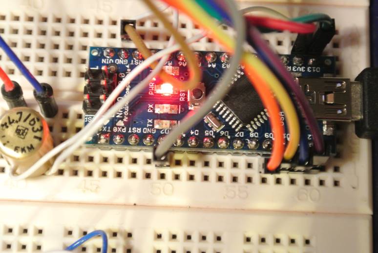
    I cant get my sensor to work. After reset I only get the message "check wires" on the serial monitor. And yes I have checked the radio Connection many times, I have attached an image with my wireing maybe someone with "new fresh" eyes can see anything. I have also connected decoupling capacitor.

    • I'm runing Nano
    • Latest download of MySensors library
    • Radio modul bought from the link on MySensors shop.
    • I run the radio from external 3.3 V (so red cabel on picture is not there anymore)
    • I run the RelayActuator sketch from the samples without any modifications
    • I have only one sensor, no gateway
    • I have tested two different Nano and two different radio
      NanoRadio4.jpg


  • Please show us a picture of wiring on the radio chip. The radio wiring at the nano (color) looks ok.
    Maybe you can test a other sketch (temperature).


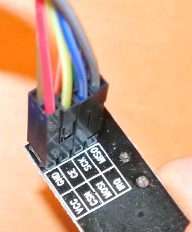
  • Here is radio wiring
    Radion3.jpg
    I don't think another sketch will help since i stop on:

      gw.begin(incomingMessage, AUTO, true);
    

    And this calls setupRadio which look like this:
    .....

     RF24::begin();
     if (!RF24::isPVariant()) {
        debug(PSTR("check wires\n"));
        while(1);
     }
    

    ...
    So it stops because it is not pVariant. BUT since I have bought the radio on MySenors link and it says on ebay that it is a NRF24L01+ i will strongly belive that it is a + variant.


  • Admin

    It could be bad wires. Have your tried replacing or testing connectivity with a multimeter?


  • Yes every wire is "beeped"


  • Admin

    What kind of cap are you using on the breadboard? Tried without it?

    I have radios confirmed working. Maybe I could send you one?


  • Admin

    @olaeke

    The wiring "howto" on the mysensor page, is using a ARduino mini, not a nano.

    Have you tried to verify the connections on schematic level for the two arduino versions? (ie. check that the different pin numbers match up to the same pin names on the atmel on the two boards)

    If I remember correctly there might be some differences. (I'm using a nano on my GW, and mini's on sensor nodes.)


  • @hek: The cap. is a electrolyt on 4.7uF so it should be Ok but i will try to remove it or decrease it to 1uF.

    @tbowmo: Is far as I can se on all spec. pages it looks like the pinout for SCK (13), MOSI (11) and MISO (12) is the same on Mini and Nano. Chip enabled and Chip select is not so critical since it is configurable in MyConfig_h but I use the default 9 and 10 for this. For The IRQ line I use #2 (INT0). IRQ line is same in Mini and Nano.


  • Interesting...I just registered because I'm having the same issue with a Arduino Pro Mini 5v. Checked wires, I've ripped it apart and rewired it multiple times, checked voltages at the radio to make sure my 5v -> 3.3v stepdown is working proper, checked continuity all the way from the radio pins to the actual SMD atmega chip itself, tried 6 different radio chips, and everything seems proper.

    Just curious, when did you buy your radio chip, and was it from Alice1101983? I bought mine via the MySensors link as well on Nov. 27th. Bought 10 chips, tried 6 so far and stopped there to start asking for help...


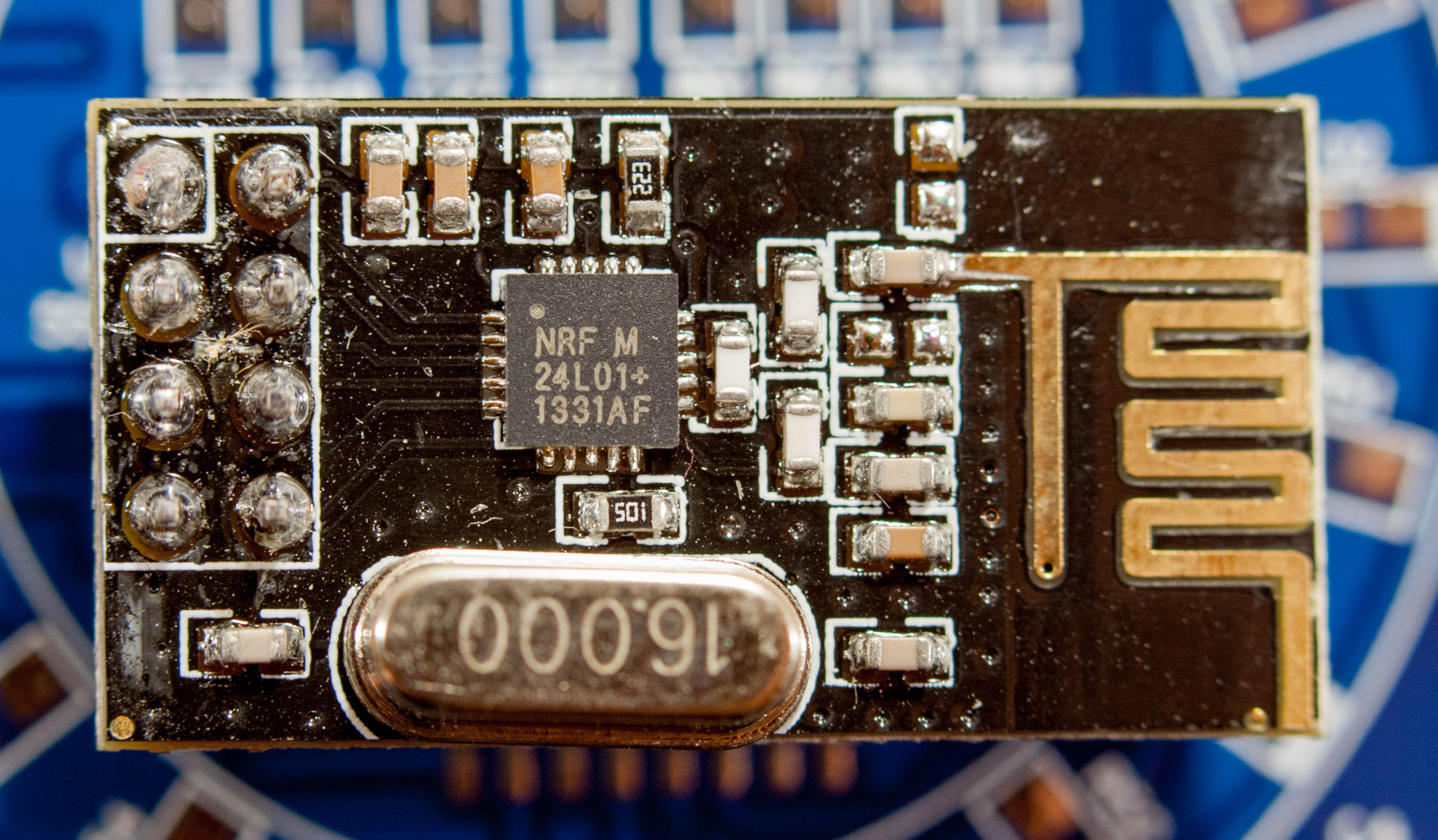
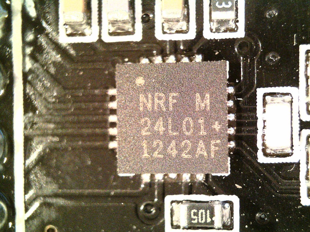
  • Hmm...If i look very closely at my radio chip, I can read the writing. and I see '24L01' in the middle, but google images found chips that say '24L01+', which is what I supposedly bought.

    @olaeke: Can you read whats on your chip?

    Can someone with a working radio look at your onboard smd chip and tell us if it says '24L01+' on it?


  • Admin

    Could you perhaps contact Alice1101983 and ask if they have changed supplier recently?

    A photo of your NRF-chip and full board makes it easier to compare.


  • Yes I bought my radios from MySensors link and I ordered them sometimes at the end of November. I will look at my chip tonight and come back.


  • Admin

    I'll contact the ebay-seller and ask some questions...


  • IMG_0006.JPG

    This is my supposed 24L01+ radio from Alice. I'll shoot the eBay seller a question, I'm guessing that chip should say '24L01+', not '24L01' 😄


  • Admin

    Just a thought... What happens if you remove the sanity check if-statment here:

    https://github.com/mysensors/Arduino/blob/master/libraries/MySensors/MySensor.cpp#L101


  • Guessing this really isn't the plus version, we'd also have to change the datarate in MyConfig.h. The data rate is defaulted to 250kbps, which is the new long range mode only supported by the + version from my understanding.

    Ok; I commented out that if check, and it doesnt throw the check wires debug anymore, but I still can't include my sensor and I was within 5 feet of my gateway. I tried changing the datarate, but then thought my gateway is also at 250kbps, so I'd have to reprogram that as well, and stopped there for now. I did look at my gateways antenna version of the nfl2401+, and it's chip does have the + sign, so these other radios are definitely not the right ones. I sent a message to the eBay seller.

    @olaeke: Hopefully this is your problem too (wrong radio chip)


  • Hero Member

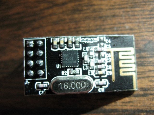
    This is what one of my NRF24 modules look like:
    _MG_3943.jpg
    I think I got them from some random AliExpress seller. So yes, it would seem some sellers started shipping old stock or something.

    And yes, this pcb is dirty as hell, and with residue from flux etc.


  • Hero Member

    I can also confirm my chips..

    20141218174253.jpg


  • @sonicblaze: Yes my radio as also without the + sign, but my antenna version is with the + sign, however I haven't have time to test this yet. I order them both at the same time from alice..... and I will also contact them now.

    Is it the same pinout on the antenna version since there is not printing on that board?


  • @olaeke I sent a message to Alice as well, I'll let you know if I hear anything. I also went on AliExpress and just ordered a pack of 10 off of there for $7.28, so hopefully I'll get proper radios one way or another...

    I've never seen any documentation that suggests the pinout is any different between the two versions. It's the same everything except an external antenna instead if on-board.


  • Just tried to find a way to concat "alice.." on ebay but whatever link I click on I end up on "You have to Contact seller trought paypal.."

    Shit so then it ends up in a new order and another 3 weeks wait for new delivery! And I also don't get my Vera as I have order 5 weeks ago so it turns out to be kind of failure with my homeautomation christmas holiday.

    No luck with Santa this year


  • Hero Member

    @bjornhallberg What did you use to take that picture?


  • @olaeke Hmm, both chips should be compatible. 24L01 (without +) not support 256k speed, but 1M or 2M should (in theory) work with new version. Did you try to set speed to 1M on both transceivers?


  • @olaeke Could you please add call to RF24::printDetails(); somewhere in your sketch and provide output?


  • Hero Member

    @ServiceXp Some old camera I have. Canon 40D + Canon EF 100mm. Plus some extension tubes. Probably not necessary but they were already attached so I didn't bother to remove them. A decent tripod. Some cfl tubes to light up the pitch dark.

    Still, as you can see the focus plane is pretty shallow (f/5.0) and I could have used some sort of light tent to apply more and softer lights. Not to mention plugged in a remote trigger and done mirror lockup to reduce shake. It's just such a hassle to set everything up though .... I should really have a dedicated place where I can have all of this set up permanently.

    And above all else, perhaps the biggest failure here and lesson 101 for macro shots, clean the object of interest first 🙂


  • Hero Member

    @bjornhallberg Thanks, I thought the detail was quite good. Much much better than my Supereyes B008 did.


  • I got a reply from the eBay seller, and they are trying to tell me "No, it's the + chip, there was just a problem with the printer at the factory". Yeah, ok, I'm sure.

    I tried adding a RF24::printDetails call right before the isPvarient if check, and it threw errors that printDetails was not defined. Any thoughts?


  • Admin

    Try one of the RF24-library example to use printDetails (but beware of CE/CSN setting when using those).


  • Admin

    I also got a reply from the ebay seller.. She needed to "check with boss". I'll forward more info when I get it.


  • Alrighty, I got the RF24 example code off GitHub and uploaded that to my chip, and sure enough dumping the details gives:
    "Model = nRF24L01"

    If anyone else wants to try it, here's the page I followed: RF24 Getting started

    Here was my message from the seller:
    dear client ,
    thanks for your pictures ,
    we have seen the it ,
    sorry for it ,we have ask for our manager ,it is the NRF24L01+ chip ,
    but there is something wrong when it is printed in the factory ,
    sorry for the mistake .
    it can be used but the it is just a little mistake for the letter ,right ?
    we will be here to help you .
    thanks in advance !"

    I'm requesting new chips or a refund, we'll see what happens....


  • Admin

    @sonicblaze said:

    I'm requesting new chips or a refund, we'll see what happens....

    Yep, do that. This is not ok.

    I'll wait a couple of days for the reply from "boss". If no answer, i'll switch recommendation to some other ebay seller.


  • @olaeke You might be able to get everything working over 1MBPS instead of the 250KBPS that's defaulted, as doctor64 suggested. I haven't tried it, but I found everywhere that'd have to be changed to make it work in theory.

    Edit <Ardunio libraries folder>/MySensors/Myconfig.h, and change the "RF24_DATARATE" to "RF24_1MBPS".

    Edit <Ardunio libraries folder>/MySensors/MySensor.cpp, and comment out lines 102-105 (the if isPVariant check)

    Recompile and upload new code to both your gateway and your sensor, and that should put them both in a mode compatible with the NRF24L01 sensor (to my best understanding/knowledge).


  • @hek: The seller responded to my last message asking if it not being the plus really affects the functionality and can't I just use it instead? Didn't even address me requesting a refund or replacement, so I'm opening an eBay dispute.


  • @sonicblaze and @hek:

    I finally had some time to test this and yes my chip is also a "non +", the RF24::printDetails(); gives:
    Model = nRF24L01

    I managaged to get RF24::printDetails(); to work in MySensor::begin after setupRadio(). There are some steps to take:

    • In RF24_config.h you have to comment out #define MINIMAL (ln 27)
    • Then in your sketch you have to define stdout like
      include "printf.h"
      void setup()
      {
      printf_begin();

    I can't contact the seller, when I click "contact seller" (or return or whatever) in ebay I only get to this page:
    "You purchased this item as a PayPal guest user and will need to contact PayPal directly by going through their Resolution Center."
    I don't understand because I payed my order with MC as usual.
    printf.h


  • Admin

    @olaeke said:

    "You purchased this item as a PayPal guest user and will need to contact PayPal directly by going through their Resolution Center."

    Do you have an ebay account?


  • @hek
    Yes I have an ebay account, I can login with this and se all my prev. orders. If I click on this radio order I come to the detail page and I select "Contact Seller" and then I come to a page with 5 topic, but whatever i select I end up on that "...Contact PayPal..." page


  • Hi. I can confirm. I have bought modules from Alice too. They are "+"-less. I had to set datarate to 1Mbps and change "check wires" to "Not 24L01+ variant or check wires" + "//" before infinite loop.
    I suggest the maker of MySensors to add "Check the chip for +" in http://www.mysensors.org/build/debug troubleshooting.
    If anyone is interested, I've even bought some chips via Aliexpress and they have no square chip. It is glued like SOIC. It was sold as +, but it is +less.


  • I bought some nrf24l01+ radios from Alice too and all I got was nrf24l01's (so without the +).
    Not happy with that, but it should be possible to use them at 1MBPS (instead of the 250KBPS speed). More higher speed, but this comes with less distance unfortunately.
    Having said that I tried to select the 1MBPS mode but now I end up with a "version mismatch' error. What else should I change in the library codes to get it work with nrf24l01's? I'm pretty stuck now 😒


  • @boozz I'd open a case on eBay and get a refund and repurchase personally 😃

    Somewhere around post 33 I put what to change for 1MBPS to function end to end, but I never tested it. I'm getting new chips instead, I want the range, not the speed.

    Otherwise, look here possibly for the version mismatch error: http://forum.mysensors.org/topic/512/strange-behaviour-check-wires-and-version-mismatch/2


  • Admin

    I have tried to get some answers from the Alice1101983 the last 5 days... but they only seem to reply with new questions (at a 24h interval)... This has become a bit tiresome and I'm giving up on them.

    I suggest that all buyers that received the non-plus NRF module to open a dispute immediately on ebay (if you haven't already accepted the delivery).
    If you payed through paypal you could also use their dispute functionality after logging in to your paypal account.

    I've decided to recommend another ebay seller for the NRF-module on http://www.mysensors.org/store now.

    I'm really sorry for the problems and project-delays this has caused you.


  • Admin

    hmm.. seems like it's a recent thing they are doing. Checkcing my ebay account, I ordered from "alice" back in september, and got the real deal..

    But yes, they should be stopped with this behaviour, selling something and then shipping old products..


  • Be prepared to argue with Alice even in the dispute. Guessing eBay themselves or PayPal will have to get involved.

    I've told them over and over it's not the plus chip, even provided the rf24::printDetails output proving it. Message I just got was "i think you First impressions are firmly entrenched in this issue .
    if you are willing to have a test it , you will find that the item you purchase from me even without the " + " can still in the same use . "

    Idiot won't even acknowledge the chips do different things, even though I've told them the data rate difference and even linked the spec sheets from Nordic.


  • Admin

    @sonicblaze said:

    Guessing eBay themselves or PayPal will have to get involved.

    http://resolutioncenter.ebay.com/


  • I have modified the excelent "ping/pong test" program from maniacbug so it compiles with the RF24 lib. that comes with MySensors 1.4

    With this program it is very easy to test your radio if it works or maybe if it works bad (many timeouts) and you also get this info printed if it is a + or non + chip.

    • Download attached zip
    • Build ino file
    • Uppload on two nodes
    • Connect serial monitor (115200 baud)
    • Press T in serial monitor and then you should se "
      Now sending 29788...ok...Got response 29788, round-trip delay: 23"

    For the printout of chip details you need to comment out #define MINIMAL in RF24_config.h. I also recommend comment SERIAL_DEBUG so you get less debuginfo on serial.
    MySensorsPingPongTst.zip


  • @olaeke:

    Great remark: "comment out #define MINIMAL". I have searched for that quite some time.

    THANKS!

    Boozz


  • FYI Alice's breaking point seems to be leaving negative feedback on their seller account. As soon as I did that, their messages immediately turned to "I'll do whatever, please change your feedback. Is a refund ok?"


  • @boozz and @sonicblaze
    Did any one of you get the non + variant to work?
    It does work with the PingPong test program (posted above) but as Gateway and/or Sensor I can't get them to work.


  • @olaeke

    Yes I got the non-plus versions to work at 1MBPS but the distance is much better with the +- version.
    Writing this I realize that I had a problem with the serial gateway. Somehow it needed a plus-version for this specific sketch to get the network running. Max distance in house approx. 6 meters (through walls, no line of Sight.

    Regards,

    Boozz


  • I can confirm that you can get non + variant to work on nodes but on the gateway you must have a + variant.

    But it is not worth the effort, if you have got non + variant from the China, throw them away and by new one (and cross your fingers that you get correct next time)


  • I finally got some + versions from AliExpress. Plugged them in, and everything came to life immediately. Amazing what happens when you receive the right parts.


  • @olaeke Can you explain why the controller needs to be "+" ?

    If we follow the speed change from the post above, does it also effect the Controller speed?

    I've just managed to get a sensor going ( non+, via the hack here at 1MB ).. ( My Chip actually shows a +, but printDetails(); shows no +
    My Controller/Gateway also is supposed to be "+", however printDetails(); shows its not + either..

    Is there a chance, I have it setup wrong and it defaults to non+ in the printDetails() output?
    The Controller doest startup and say "Started!"..


  • Admin

    You don't have to have the + variant.

    To get the none+ variant started I guess you have to remove the sanity check ("check wires") in MySensor.cpp (besides changing the transfer speed to 1Mbit in MyConfig.h).


  • @Squint I have problem with Ack and I have assumed that it has to do with the non + . I have a + variant on my gateway but non puls on my sensor node.


  • @olaeke I believe this is how I have mine setup as well.. Oddly enough both modules have the "+" printed on the chip but I cannot get the sensor code to initialize unless i take out the PVariant check. printDetails shows the following:

    Gateway:
    Data Rate = 2MBPS
    Model = nRF24L01+

    Sensor:
    STATUS = 0x00 RX_DR=0 TX_DS=0 MAX_RT=0 RX_P_NO=0 TX_FULL=0
    RX_ADDR_P0-1 x00 = 0x0000000000 0x0000000000
    RX_ADDR_P2-5 x00 = 0x00 0x00 0x00 0x00
    TX_ADDR = 0x0000000000
    RX_PW_P0-6 x00 = 0x00 0x00 0x00 0x00 0x00 0x00
    EN_AA = 0x00
    EN_RXADDR x00 = 0x00
    RF_CH = 0x00
    RF_SETUP x00 = 0x00
    CONFIG = 0x00
    DYNPD/FEATURE x00 = 0x00 0x00
    Data Rate = 1MBPS
    Model = nRF24L01
    CRC Length = Disabled
    PA Power = PA_MIN

    The odd part is, on the sensor - all of the values in printDetails(); are 0's.. So I suspect I have something wired incorrectly?
    I've double & tripple checked the wiring..

    Thanks.


  • @Squint That seem even more tricky that the have printed + on the chip and then it still is non plus.

    I really don't remember now if I run the getstatus() on the sensor node or it was only on the gateway, but it sound strange that you get zeros on all information. The only thing I can think of is either is the radio broken or is there som more #define in the code you have to comment out the get the status info to print correctly.

    I will also remember that I had to fix some more issue in the code to get the non plus to work, I think a made a hack in the process method in the MySensor class, and still the acknowledge didn't work. But I'm not totally shure, I have had a lot of problem with my sensors and my Vera Edge.

    Yesterday I received my new radios (yes + variant) and my Ethernet shield. I have now replaced my radios, replaced the serial gateway with Ethernet (the serial port is not working on Vera Egde, good work Mi Casa Verde!) replaced all my hacked library code with fresh from MySensors.org and...

    NOW IT WORKS!

    I will take the old non plus radio and burn them in the garden tomorrow!

    FYI as sonicblaze wrote is Alice breaking point to give them bad feedback then they contact you within a week and offer you refund,.


  • @olaeke It turns out mine were actually + models. I had the sensors wired incorrectly because I had SOFTSPI enabled.. Once I realized the correct pinout ( After about 3 days of trial/error/code-digging ) its now reporting the + as it should and the radios are working as intended.

    Thanks!


  • This post is deleted!


  • @olaeke

    I can not get it to work.

    The pins I use on nRF24L01 + / nRF24L01

    Arduino NRF24L01 Radio Ethernet module
    GND GND
    3.3V VCC
    13 SCK
    12 MISO
    11 MOSI
    6 CSN
    5 CE

    And what I get is this

    STATUS = 0x00 RX_DR=0 TX_DS=0 MAX_RT=0 RX_P_NO=0 TX_FULL=0
    RX_ADDR_P0-1 = 0x0000000000 0x0000000000
    RX_ADDR_P2-5 = 0x00 0x00 0x00 0x00
    TX_ADDR = 0x0000000000
    RX_PW_P0-6 = 0x00 0x00 0x00 0x00 0x00 0x00
    EN_AA = 0x00
    EN_RXADDR = 0x00
    RF_CH = 0x00
    RF_SETUP = 0x00
    CONFIG = 0x00
    DYNPD/FEATURE = 0x00 0x00
    Data Rate = 1MBPS
    Model = nRF24L01
    CRC Length = Disabled
    PA Power = PA_MIN

    What am I doing wrong?


  • Mod

    @MLs what else is connected to arduino?

    i had the same result yesterday trying to build ethernet gateway using ENC based shield. I'm faced a conflict between radio and ethernet


  • @axillent

    Four Dallas temp sensor.

    But what I am interested in is the model I have (nRF24L01 + / nRF24L01) and not to send / receive data.


  • Mod

    @MLs if you have original nordic you will see + for the plus version
    IMG_2048.JPG


  • @axillent

    I bought them through the store available here at Mysensors


  • Mod

    @MLs it should be OK
    the old version is out of production for years


  • @axillent

    Possible, but now I wanted to read it out of the hardware to be sure.


  • Mod

    @MLs said:

    Possible, but now I wanted to read it out of the hardware to be sure.

    that is easy))) check wires


  • @axillent

    As I wrote earlier, it is linked and I have also measured the cables to minimize errors.


  • Mod

    @MLs disconnect all from arduino

    connect radio as stated here http://www.mysensors.org/build/connect_radio
    get example GetStarted sketch from RF24 library and see the output

    it should be OK
    otherwise most probably the radio is broken


  • Admin

    @axillent said:

    the old version is out of production for years

    But they still seem to pop up. See a bit up in the thread.


  • Mod

    @hek you knew from our conversation last night that I also got "check wires" and was ready to think that all my modules are the old ones

    but finally my issue has nothing to do with version of the chip. It is exactly "check wires" issue and issue of the conflicts with other staff,
    and my modules were purchased about two years ago

    is it any confirmed case with the old version?


  • Admin

    @axillent
    Yep, if you look at the pictures above they're missing +


  • Mod

    @hek you are right
    but it seams that only @sonicblaze is owner of this rare thing


  • @axillent And me! I started the thread so I have got 10 of the them, maybe something for the MySensors museum!


  • Mod

    @olaeke said:

    @axillent And me! I started the thread so I have got 10 of the them, maybe something for the MySensors museum!

    hm. are the + is missing on top of the nordic chip?

    it can be probably still used for mysensors in case of:

    • switching data rate to 1Mbs or 2MBs (old version do not support 250Kbs - default to 1.4)
    • comment out "check wires" check inside Mysensors library


  • @axillent Yes there is no + on those.
    I have tried using them but without success. I couldn't get them to work at all on the gateway but if I replaced the gateway with + variant and non + on the node then it "almost" worked. I couldn't get the "Auto Id" function to work. I think it has something with Ack to do, i will remember that I have read somewhere that the hardware ack is only implemented in the + variant.


  • Hello,

    I'am a new one on this forum, and I've stepped on the same rake like others. So there are some recommendations for other newbies and questions for developers:

    1. I've wasted some hours because this library uses serial baud rate 115200, not 9600, what is default for other projects - it should be mentioned in proper place, sorry, if it is, but I've not noticed it.

    2. Next step for all users, that want to use this great project, should be sketch that outputs NRF24L01 version: my history is, that I've bought 10 NRF's from the same seller (alice***) 2-3 months ago, on chips there is "+" sign, but sketch says, that there is NRF24L01 without "+" 😞

    3. What to do for those unlucky, that bought wrong version: maybe it's possible to use these modules with some restrictions, while right modules will arrive? I saw recommendations about sensor node to change speed and comment out while()1) after "check cables", but what to do for gateway node?

    4. I'm not a geek developer, maybe it is possible to use #define SOFTSPI in main sketch, before including other libraries? It would be simpler, than editing file RF24_config.h for gateway node and sensor node?

    Thanks!


  • Admin

    @eimis said:

    I've wasted some hours because this library uses serial baud rate 115200, not 9600, what is default for other projects - it should be mentioned in proper place, sorry, if it is, but I've not noticed it.

    It is mentioned at a few places on the main site. Anywhere particular place it is missing?

    I'm not a geek developer, maybe it is possible to use #define SOFTSPI in main sketch, before including other libraries? It would be simpler, than editing file RF24_config.h for gateway node and sensor node?

    Unfortunately the Arduino IDE build system is f**cked up and does not allow this. But I agree that DEBUG and SOFTSPI would had been great to add in the sketch itself.


  • @hek said:

    @eimis said:

    I've wasted some hours because this library uses serial baud rate 115200, not 9600, what is default for other projects - it should be mentioned in proper place, sorry, if it is, but I've not noticed it.

    It is mentioned at a few places on the main site. Anywhere particular place it is missing?

    I've started from "Building Ethernet Gateway" and finished on "MQTT Gateway", as I use OpenHAB as Controller.


  • Hardware Contributor

    Hm what's this? I haven't had time to test it yet, but it looks very suspicious. I'm pretty sure I ordered via MyS store on Jan 10 (soon after the Ali-links just were introduced). Is it worth the hassle to test or should I throw it straight into the garbage and order a new batch from a proven supplier (which one)?
    Bought it from here.
    ny_nrf24.jpg


  • Mod

    @m26872 this is most probably based on a Chinese clone of the nordic chip

    it could probably work
    At least nobody will charge you for the try 🙂


  • @m26872 Didn't work for me. Please tell me how you do.


  • Mod

    @slarti start from the RF24 example named GettingStarted
    connect wires according to hek's instruction http://www.mysensors.org/build/connect_radio


  • @axillent I tried it and it worked with the modules but none of the MySensors example sketches work with them. Thread about it.


  • Mod

    @slarti what is the output from printDetails ?

    is your chip recognized as NRF24L01+ or just NRF24L01?


  • @axillent That's the funny thing, they were recognized as NRF24L01+ but still refuse to work. I don't get "check wires". I just don't get anything.


  • Mod

    @slarti getting nothing is already something)

    GettingStarted can be used to connect two arduinos. Have you tested this? You told that examples are working.


  • Admin

    Might be possible to tweak initialization to get them to work. If someone has too much time on their hands this could be added as a new RFM73 driver in the development branch.

    http://forum.mysensors.org/topic/300/rfm73-experience/14


  • @axillent Yes, the pingpong sketch from @olaeke works after I import the MySensors library to the sketch and comment out
    //#include "nRF24L01.h" //#include "RF24.h"
    and
    #define MINIMAL from RF24_config.h

    None of the "normal" examples work or give anything over serial.


  • Mod

    @slarti it is probably a limited set of configurable parameters are allowed for your chip

    you can investigate this but no success guaranteed


  • We'll know tomorrow or the day after as I found a Finnish guy with some radios that should be either the real thing or the SI24R1 -clone that should work.


  • Hardware Contributor

    Thank you for the info. I never inteded to develop any driver so I will simply buy a new batch with more care this time.


  • @slarti You can test to set a static id on the sensor in the gw.begin like;

    gw.begin(NULL, 25);
    

    this sample set id fixed to 25 on this node. At least that was one of my problem with this radios, but my advice is to by new radios the cost is so smal compared to the effort. However it is the shiping that is the problem.


  • @olaeke Thanks, made it easy to test the new radios I got today.

    If someone in Europe needs to get radios fast, try this guy in Finland. He advertises the radios as NRF24L01, but they are in fact NRF24L01+.


  • @slarti HaHa so in China they sell NRF24L01+. and you get NRF24L01 but in Finland they sell NRF24L01 and you get NRF24L01+. 🙂


  • Hi everybpdy.....any news on this topic?

    my radio chips say NRF24L01+, however are detected as NRF24L01.

    Got 3 of em working perfectly on Uno and Nano...but on pro mini always gettin the f**n "check wires" message...the only difference is the regulator (I'm using arduino pro mini 5V), but i checked and radio is getin 3.3 as it should be.


Log in to reply
 

Suggested Topics

  • 3
  • 3
  • 2
  • 1
  • 2
  • 2

0
Online

11.2k
Users

11.1k
Topics

112.5k
Posts