Radio setup give: "check wires"


  • Admin

    I have tried to get some answers from the Alice1101983 the last 5 days... but they only seem to reply with new questions (at a 24h interval)... This has become a bit tiresome and I'm giving up on them.

    I suggest that all buyers that received the non-plus NRF module to open a dispute immediately on ebay (if you haven't already accepted the delivery).
    If you payed through paypal you could also use their dispute functionality after logging in to your paypal account.

    I've decided to recommend another ebay seller for the NRF-module on http://www.mysensors.org/store now.

    I'm really sorry for the problems and project-delays this has caused you.


  • Admin

    hmm.. seems like it's a recent thing they are doing. Checkcing my ebay account, I ordered from "alice" back in september, and got the real deal..

    But yes, they should be stopped with this behaviour, selling something and then shipping old products..


  • Be prepared to argue with Alice even in the dispute. Guessing eBay themselves or PayPal will have to get involved.

    I've told them over and over it's not the plus chip, even provided the rf24::printDetails output proving it. Message I just got was "i think you First impressions are firmly entrenched in this issue .
    if you are willing to have a test it , you will find that the item you purchase from me even without the " + " can still in the same use . "

    Idiot won't even acknowledge the chips do different things, even though I've told them the data rate difference and even linked the spec sheets from Nordic.


  • Admin

    @sonicblaze said:

    Guessing eBay themselves or PayPal will have to get involved.

    http://resolutioncenter.ebay.com/


  • I have modified the excelent "ping/pong test" program from maniacbug so it compiles with the RF24 lib. that comes with MySensors 1.4

    With this program it is very easy to test your radio if it works or maybe if it works bad (many timeouts) and you also get this info printed if it is a + or non + chip.

    • Download attached zip
    • Build ino file
    • Uppload on two nodes
    • Connect serial monitor (115200 baud)
    • Press T in serial monitor and then you should se "
      Now sending 29788...ok...Got response 29788, round-trip delay: 23"

    For the printout of chip details you need to comment out #define MINIMAL in RF24_config.h. I also recommend comment SERIAL_DEBUG so you get less debuginfo on serial.
    MySensorsPingPongTst.zip


  • @olaeke:

    Great remark: "comment out #define MINIMAL". I have searched for that quite some time.

    THANKS!

    Boozz


  • FYI Alice's breaking point seems to be leaving negative feedback on their seller account. As soon as I did that, their messages immediately turned to "I'll do whatever, please change your feedback. Is a refund ok?"


  • @boozz and @sonicblaze
    Did any one of you get the non + variant to work?
    It does work with the PingPong test program (posted above) but as Gateway and/or Sensor I can't get them to work.


  • @olaeke

    Yes I got the non-plus versions to work at 1MBPS but the distance is much better with the +- version.
    Writing this I realize that I had a problem with the serial gateway. Somehow it needed a plus-version for this specific sketch to get the network running. Max distance in house approx. 6 meters (through walls, no line of Sight.

    Regards,

    Boozz


  • I can confirm that you can get non + variant to work on nodes but on the gateway you must have a + variant.

    But it is not worth the effort, if you have got non + variant from the China, throw them away and by new one (and cross your fingers that you get correct next time)


  • I finally got some + versions from AliExpress. Plugged them in, and everything came to life immediately. Amazing what happens when you receive the right parts.


  • @olaeke Can you explain why the controller needs to be "+" ?

    If we follow the speed change from the post above, does it also effect the Controller speed?

    I've just managed to get a sensor going ( non+, via the hack here at 1MB ).. ( My Chip actually shows a +, but printDetails(); shows no +
    My Controller/Gateway also is supposed to be "+", however printDetails(); shows its not + either..

    Is there a chance, I have it setup wrong and it defaults to non+ in the printDetails() output?
    The Controller doest startup and say "Started!"..


  • Admin

    You don't have to have the + variant.

    To get the none+ variant started I guess you have to remove the sanity check ("check wires") in MySensor.cpp (besides changing the transfer speed to 1Mbit in MyConfig.h).


  • @Squint I have problem with Ack and I have assumed that it has to do with the non + . I have a + variant on my gateway but non puls on my sensor node.


  • @olaeke I believe this is how I have mine setup as well.. Oddly enough both modules have the "+" printed on the chip but I cannot get the sensor code to initialize unless i take out the PVariant check. printDetails shows the following:

    Gateway:
    Data Rate = 2MBPS
    Model = nRF24L01+

    Sensor:
    STATUS = 0x00 RX_DR=0 TX_DS=0 MAX_RT=0 RX_P_NO=0 TX_FULL=0
    RX_ADDR_P0-1 x00 = 0x0000000000 0x0000000000
    RX_ADDR_P2-5 x00 = 0x00 0x00 0x00 0x00
    TX_ADDR = 0x0000000000
    RX_PW_P0-6 x00 = 0x00 0x00 0x00 0x00 0x00 0x00
    EN_AA = 0x00
    EN_RXADDR x00 = 0x00
    RF_CH = 0x00
    RF_SETUP x00 = 0x00
    CONFIG = 0x00
    DYNPD/FEATURE x00 = 0x00 0x00
    Data Rate = 1MBPS
    Model = nRF24L01
    CRC Length = Disabled
    PA Power = PA_MIN

    The odd part is, on the sensor - all of the values in printDetails(); are 0's.. So I suspect I have something wired incorrectly?
    I've double & tripple checked the wiring..

    Thanks.


  • @Squint That seem even more tricky that the have printed + on the chip and then it still is non plus.

    I really don't remember now if I run the getstatus() on the sensor node or it was only on the gateway, but it sound strange that you get zeros on all information. The only thing I can think of is either is the radio broken or is there som more #define in the code you have to comment out the get the status info to print correctly.

    I will also remember that I had to fix some more issue in the code to get the non plus to work, I think a made a hack in the process method in the MySensor class, and still the acknowledge didn't work. But I'm not totally shure, I have had a lot of problem with my sensors and my Vera Edge.

    Yesterday I received my new radios (yes + variant) and my Ethernet shield. I have now replaced my radios, replaced the serial gateway with Ethernet (the serial port is not working on Vera Egde, good work Mi Casa Verde!) replaced all my hacked library code with fresh from MySensors.org and...

    NOW IT WORKS!

    I will take the old non plus radio and burn them in the garden tomorrow!

    FYI as sonicblaze wrote is Alice breaking point to give them bad feedback then they contact you within a week and offer you refund,.


  • @olaeke It turns out mine were actually + models. I had the sensors wired incorrectly because I had SOFTSPI enabled.. Once I realized the correct pinout ( After about 3 days of trial/error/code-digging ) its now reporting the + as it should and the radios are working as intended.

    Thanks!


  • This post is deleted!


  • @olaeke

    I can not get it to work.

    The pins I use on nRF24L01 + / nRF24L01

    Arduino NRF24L01 Radio Ethernet module
    GND GND
    3.3V VCC
    13 SCK
    12 MISO
    11 MOSI
    6 CSN
    5 CE

    And what I get is this

    STATUS = 0x00 RX_DR=0 TX_DS=0 MAX_RT=0 RX_P_NO=0 TX_FULL=0
    RX_ADDR_P0-1 = 0x0000000000 0x0000000000
    RX_ADDR_P2-5 = 0x00 0x00 0x00 0x00
    TX_ADDR = 0x0000000000
    RX_PW_P0-6 = 0x00 0x00 0x00 0x00 0x00 0x00
    EN_AA = 0x00
    EN_RXADDR = 0x00
    RF_CH = 0x00
    RF_SETUP = 0x00
    CONFIG = 0x00
    DYNPD/FEATURE = 0x00 0x00
    Data Rate = 1MBPS
    Model = nRF24L01
    CRC Length = Disabled
    PA Power = PA_MIN

    What am I doing wrong?


  • Mod

    @MLs what else is connected to arduino?

    i had the same result yesterday trying to build ethernet gateway using ENC based shield. I'm faced a conflict between radio and ethernet


  • @axillent

    Four Dallas temp sensor.

    But what I am interested in is the model I have (nRF24L01 + / nRF24L01) and not to send / receive data.


  • Mod

    @MLs if you have original nordic you will see + for the plus version
    IMG_2048.JPG


  • @axillent

    I bought them through the store available here at Mysensors


  • Mod

    @MLs it should be OK
    the old version is out of production for years


  • @axillent

    Possible, but now I wanted to read it out of the hardware to be sure.


  • Mod

    @MLs said:

    Possible, but now I wanted to read it out of the hardware to be sure.

    that is easy))) check wires


  • @axillent

    As I wrote earlier, it is linked and I have also measured the cables to minimize errors.


  • Mod

    @MLs disconnect all from arduino

    connect radio as stated here http://www.mysensors.org/build/connect_radio
    get example GetStarted sketch from RF24 library and see the output

    it should be OK
    otherwise most probably the radio is broken


  • Admin

    @axillent said:

    the old version is out of production for years

    But they still seem to pop up. See a bit up in the thread.


  • Mod

    @hek you knew from our conversation last night that I also got "check wires" and was ready to think that all my modules are the old ones

    but finally my issue has nothing to do with version of the chip. It is exactly "check wires" issue and issue of the conflicts with other staff,
    and my modules were purchased about two years ago

    is it any confirmed case with the old version?


  • Admin

    @axillent
    Yep, if you look at the pictures above they're missing +


  • Mod

    @hek you are right
    but it seams that only @sonicblaze is owner of this rare thing


  • @axillent And me! I started the thread so I have got 10 of the them, maybe something for the MySensors museum!


  • Mod

    @olaeke said:

    @axillent And me! I started the thread so I have got 10 of the them, maybe something for the MySensors museum!

    hm. are the + is missing on top of the nordic chip?

    it can be probably still used for mysensors in case of:

    • switching data rate to 1Mbs or 2MBs (old version do not support 250Kbs - default to 1.4)
    • comment out "check wires" check inside Mysensors library


  • @axillent Yes there is no + on those.
    I have tried using them but without success. I couldn't get them to work at all on the gateway but if I replaced the gateway with + variant and non + on the node then it "almost" worked. I couldn't get the "Auto Id" function to work. I think it has something with Ack to do, i will remember that I have read somewhere that the hardware ack is only implemented in the + variant.


  • Hello,

    I'am a new one on this forum, and I've stepped on the same rake like others. So there are some recommendations for other newbies and questions for developers:

    1. I've wasted some hours because this library uses serial baud rate 115200, not 9600, what is default for other projects - it should be mentioned in proper place, sorry, if it is, but I've not noticed it.

    2. Next step for all users, that want to use this great project, should be sketch that outputs NRF24L01 version: my history is, that I've bought 10 NRF's from the same seller (alice***) 2-3 months ago, on chips there is "+" sign, but sketch says, that there is NRF24L01 without "+" 😞

    3. What to do for those unlucky, that bought wrong version: maybe it's possible to use these modules with some restrictions, while right modules will arrive? I saw recommendations about sensor node to change speed and comment out while()1) after "check cables", but what to do for gateway node?

    4. I'm not a geek developer, maybe it is possible to use #define SOFTSPI in main sketch, before including other libraries? It would be simpler, than editing file RF24_config.h for gateway node and sensor node?

    Thanks!


  • Admin

    @eimis said:

    I've wasted some hours because this library uses serial baud rate 115200, not 9600, what is default for other projects - it should be mentioned in proper place, sorry, if it is, but I've not noticed it.

    It is mentioned at a few places on the main site. Anywhere particular place it is missing?

    I'm not a geek developer, maybe it is possible to use #define SOFTSPI in main sketch, before including other libraries? It would be simpler, than editing file RF24_config.h for gateway node and sensor node?

    Unfortunately the Arduino IDE build system is f**cked up and does not allow this. But I agree that DEBUG and SOFTSPI would had been great to add in the sketch itself.


  • @hek said:

    @eimis said:

    I've wasted some hours because this library uses serial baud rate 115200, not 9600, what is default for other projects - it should be mentioned in proper place, sorry, if it is, but I've not noticed it.

    It is mentioned at a few places on the main site. Anywhere particular place it is missing?

    I've started from "Building Ethernet Gateway" and finished on "MQTT Gateway", as I use OpenHAB as Controller.


  • Hardware Contributor

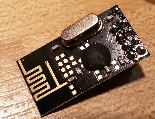
    Hm what's this? I haven't had time to test it yet, but it looks very suspicious. I'm pretty sure I ordered via MyS store on Jan 10 (soon after the Ali-links just were introduced). Is it worth the hassle to test or should I throw it straight into the garbage and order a new batch from a proven supplier (which one)?
    Bought it from here.
    ny_nrf24.jpg


  • Mod

    @m26872 this is most probably based on a Chinese clone of the nordic chip

    it could probably work
    At least nobody will charge you for the try 🙂


  • @m26872 Didn't work for me. Please tell me how you do.


  • Mod

    @slarti start from the RF24 example named GettingStarted
    connect wires according to hek's instruction http://www.mysensors.org/build/connect_radio


  • @axillent I tried it and it worked with the modules but none of the MySensors example sketches work with them. Thread about it.


  • Mod

    @slarti what is the output from printDetails ?

    is your chip recognized as NRF24L01+ or just NRF24L01?


  • @axillent That's the funny thing, they were recognized as NRF24L01+ but still refuse to work. I don't get "check wires". I just don't get anything.


  • Mod

    @slarti getting nothing is already something)

    GettingStarted can be used to connect two arduinos. Have you tested this? You told that examples are working.


  • Admin

    Might be possible to tweak initialization to get them to work. If someone has too much time on their hands this could be added as a new RFM73 driver in the development branch.

    http://forum.mysensors.org/topic/300/rfm73-experience/14


  • @axillent Yes, the pingpong sketch from @olaeke works after I import the MySensors library to the sketch and comment out
    //#include "nRF24L01.h" //#include "RF24.h"
    and
    #define MINIMAL from RF24_config.h

    None of the "normal" examples work or give anything over serial.


  • Mod

    @slarti it is probably a limited set of configurable parameters are allowed for your chip

    you can investigate this but no success guaranteed


  • We'll know tomorrow or the day after as I found a Finnish guy with some radios that should be either the real thing or the SI24R1 -clone that should work.


  • Hardware Contributor

    Thank you for the info. I never inteded to develop any driver so I will simply buy a new batch with more care this time.


  • @slarti You can test to set a static id on the sensor in the gw.begin like;

    gw.begin(NULL, 25);
    

    this sample set id fixed to 25 on this node. At least that was one of my problem with this radios, but my advice is to by new radios the cost is so smal compared to the effort. However it is the shiping that is the problem.


  • @olaeke Thanks, made it easy to test the new radios I got today.

    If someone in Europe needs to get radios fast, try this guy in Finland. He advertises the radios as NRF24L01, but they are in fact NRF24L01+.


  • @slarti HaHa so in China they sell NRF24L01+. and you get NRF24L01 but in Finland they sell NRF24L01 and you get NRF24L01+. 🙂


  • Hi everybpdy.....any news on this topic?

    my radio chips say NRF24L01+, however are detected as NRF24L01.

    Got 3 of em working perfectly on Uno and Nano...but on pro mini always gettin the f**n "check wires" message...the only difference is the regulator (I'm using arduino pro mini 5V), but i checked and radio is getin 3.3 as it should be.


Log in to reply
 

Suggested Topics

0
Online

11.2k
Users

11.1k
Topics

112.5k
Posts