💬 MySensors Low-power Multi-function node on CR2032
-
@pihome I don't know yet, I'm still waiting for the PCB. I should receive them this week. From the mysensors site, 1Mhz vs 8Mhz does not make a huge difference. I'll try them both. What I can say is that 1Mhz as other constraints (I had to compile my own bootloader, then it is difficult to have reliable serial communication faster than 9600bauds, including for uploading sketches, meaning an update in the boards.txt file). Anyway, for sure, I'll build the board and make tests very soon. In the worst scenario, I may switch to CR123 batteries or LS14250.
@fanfan
I been using temperature sensors with 8Mhz without any custom bootloader or any other modifications on 18650 battery for over 2 years, sensor read temperature once every minute and go to sleep, haven’t done any battery consumption calculations, i m switching from 18650 battery to AAA or AA batteries hence need for power saving -
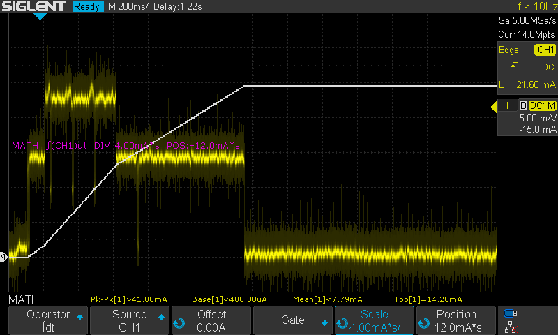
@pihome I finally built it. There will still be some adjustments (routing for cutting castelized holes, diode protections removal, ...), but it works. Be careful, it is designed to have 2V-3.6V for power AND signals (double check your ICSP and FTDI programmers). The battery duration depends on your sketch (sleep time, transmission power, encryption ...), your battery (mAh), your sensors (I only have BME280 connected) and your gateway distance. I can tell you that it uses 13mA during transmissions at PA_MAX.
-
@Fanfan 20mA during transmission is higher then mine but then i have cheap chines version of multimeter may be its not very accurate as yours. are you using any low clock bootloader?
Power consumption with onboard regulator and onboard LEDs removed without any further modification:
18.11 mA startup
66.9 uA during sleeping
3.01 mA during TransmissionPro mini with 1mhz bootloader and on board regulator/LEDs removed:
14.42 mA startup
7.50 uA during sleeping
1.40 mA during Transmission -
@pihome I did compile my own dualoptiboot for 1Mhz support. My board does not use any LDO (I am supposed to only plug 3V power supply, not more). The LED is not a "power LED" but a LED connected to A2 to be used (or not) by the sketch. I might have more current consumption because I use PA_MAX as transmission power. or because my sketch does not put BME280 in sleep mode (yet). I still need to rework on the schema and PCB to tune/optimize it (no need for the zener, the schottky and the FTDI connector), but the proof of concept for my very first real design works.
-
@pihome I did compile my own dualoptiboot for 1Mhz support. My board does not use any LDO (I am supposed to only plug 3V power supply, not more). The LED is not a "power LED" but a LED connected to A2 to be used (or not) by the sketch. I might have more current consumption because I use PA_MAX as transmission power. or because my sketch does not put BME280 in sleep mode (yet). I still need to rework on the schema and PCB to tune/optimize it (no need for the zener, the schottky and the FTDI connector), but the proof of concept for my very first real design works.
@fanfan , not sure if that may help you, but in my case I discovered that even in sleep mode the BME280 still drawing current (up to 1mA). The only solution I found was to bring down the SCL and SDA pins before entering in the sleep mode.
Something like this:
digitalWrite( A4 , LOW );
digitalWrite( A5 , LOW );
sleep( 60000 );

wait(200);
weather_sensor.begin();
wait(200);
Not sure if this is best way but it worked for me...
-
@fanfan , not sure if that may help you, but in my case I discovered that even in sleep mode the BME280 still drawing current (up to 1mA). The only solution I found was to bring down the SCL and SDA pins before entering in the sleep mode.
Something like this:
digitalWrite( A4 , LOW );
digitalWrite( A5 , LOW );
sleep( 60000 );

wait(200);
weather_sensor.begin();
wait(200);
Not sure if this is best way but it worked for me...
@rvendrame Thanks a lot, I'm currently working on another project (electronic load). But I keep your idea in mind and will investigate when I'll continue this sensors project.
-
@rvendrame sorry, I did not see your comment. Yes, it is VERY valuable. Thanks a lot
Hello! It looks like you're interested in this conversation, but you don't have an account yet.
Getting fed up of having to scroll through the same posts each visit? When you register for an account, you'll always come back to exactly where you were before, and choose to be notified of new replies (either via email, or push notification). You'll also be able to save bookmarks and upvote posts to show your appreciation to other community members.
With your input, this post could be even better 💗
Register Login