nRF5 action!
-
@d00616 said in nRF5 Bluetooth action!:
P.S.: you can reduce the RX/TX time by enabling fast ramp up in MODECNF0 if you haven't to care about nRF51 compatibility.
Thanks for the tip. I tried it both ways. The first scope capture below is taken without MODECNF0 enabled on bit 0, and the second is with it enabled on bit 0.
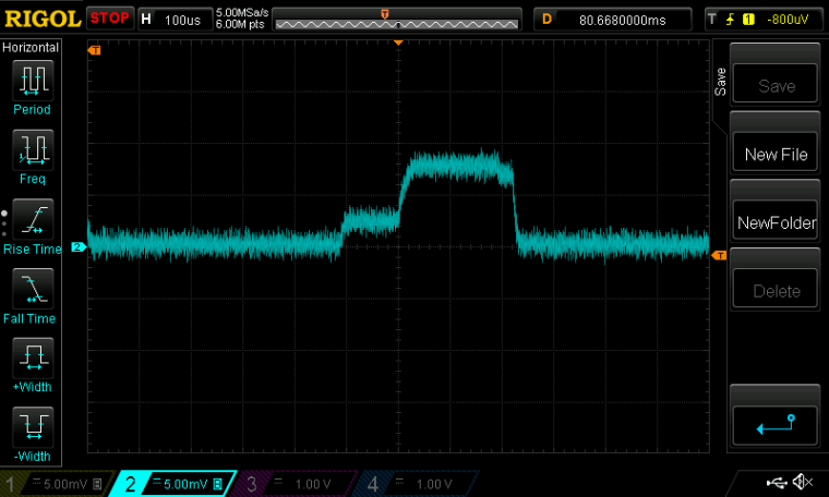
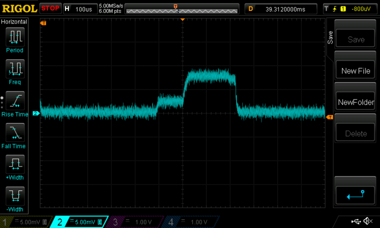
I don't really see any difference. Do you?
Scale: 1mv=1ma. Scope captures of current drawn.Maybe @jokgi can comment? His bio says he's a Senior Field Application Engineer at Nordic Semiconductor.
Maybe he sees (or knows) something that's not apparent about the fast ramp enable bit?
-
@NeverDie said in nRF5 Bluetooth action!:
Whenever I use:
#include <MySensors.h>on the nRF52832, there is around a 10 second delay between the end of "void startup()" and the beginning of "loop()". Why is that, and what is the MySensors library doing during that interval?
As an alternative, you can define '#define MY_CORE_ONLY' and use ' transportInit(); transportSetAddress(MY_NODE_ID);' to initialize the radio. This dosn't work at the moment with the nRF5. I'm currently looking what the reason is. All radio registers are equal when it's initialized after MySensors normal and my setup(). It's not able to send or receive packages.
Maybe someone has an idea about the reason. Here is my code for nRF5 and other with nRF24.
// Undefine to work in gateway mode
#define MY_CORE_ONLY


#define MY_NODE_ID (0)

// Enable debug
#define MY_DEBUG
#define MY_DEBUG_VERBOSE_RF24
#define MY_DEBUG_VERBOSE_NRF5_ESB

// Enable and select radio type attached
#ifndef ARDUINO_ARCH_NRF5
#define MY_RADIO_NRF24
#else
#define MY_RADIO_NRF5_ESB
#include <nrf.h>
#endif
//#define MY_RADIO_RFM69
//#define MY_RADIO_RFM95

//#define MY_OTA_LOG_SENDER_FEATURE
//#define MY_OTA_LOG_RECEIVER_FEATURE

#ifndef MY_CORE_ONLY
#define MY_GATEWAY_SERIAL
#endif
#include <MySensors.h>

void state() {
#ifdef ARDUINO_ARCH_NRF5
 Serial.println("----------------------------------");
 Serial.print("NRF_RADIO->STATE  ");
 Serial.println(NRF_RADIO->STATE, HEX);
 Serial.print("NRF_RADIO->EVENTS_READY  ");
 Serial.println(NRF_RADIO->EVENTS_READY, HEX);
 Serial.print("NRF_RADIO->EVENTS_ADDRESS  ");
 Serial.println(NRF_RADIO->EVENTS_ADDRESS, HEX);
 Serial.print("NRF_RADIO->EVENTS_PAYLOAD  ");
 Serial.println(NRF_RADIO->EVENTS_PAYLOAD, HEX);
 Serial.print("NRF_RADIO->EVENTS_END  ");
 Serial.println(NRF_RADIO->EVENTS_END, HEX);
 Serial.print("NRF_RADIO->EVENTS_DISABLED  ");
 Serial.println(NRF_RADIO->EVENTS_DISABLED, HEX);
 Serial.print("NRF_RADIO->EVENTS_DEVMATCH  ");
 Serial.println(NRF_RADIO->EVENTS_DEVMATCH, HEX);
 Serial.print("NRF_RADIO->EVENTS_DEVMISS  ");
 Serial.println(NRF_RADIO->EVENTS_DEVMISS, HEX);
 Serial.print("NRF_RADIO->EVENTS_RSSIEND  ");
 Serial.println(NRF_RADIO->EVENTS_RSSIEND, HEX);
 Serial.print("NRF_RADIO->EVENTS_BCMATCH  ");
 Serial.println(NRF_RADIO->EVENTS_BCMATCH, HEX);
 Serial.print("NRF_RADIO->CRCSTATUS  ");
 Serial.println(NRF_RADIO->CRCSTATUS, HEX);
 Serial.print("NRF_RADIO->RXMATCH  ");
 Serial.println(NRF_RADIO->RXMATCH, HEX);
 Serial.print("NRF_RADIO->RXCRC  ");
 Serial.println(NRF_RADIO->RXCRC, HEX);
 Serial.print("NRF_RADIO->DAI  ");
 Serial.println(NRF_RADIO->DAI, HEX);
 Serial.print("NRF_RADIO->PACKETPTR  ");
 Serial.println(NRF_RADIO->PACKETPTR, HEX);
 Serial.print("NRF_RADIO->FREQUENCY  ");
 Serial.println(NRF_RADIO->FREQUENCY, HEX);
 Serial.print("NRF_RADIO->TXPOWER  ");
 Serial.println(NRF_RADIO->TXPOWER, HEX);
 Serial.print("NRF_RADIO->MODE  ");
 Serial.println(NRF_RADIO->MODE, HEX);
 Serial.print("NRF_RADIO->PCNF0  ");
 Serial.println(NRF_RADIO->PCNF0, HEX);
 Serial.print("NRF_RADIO->PCNF1  ");
 Serial.println(NRF_RADIO->PCNF1, HEX);
 Serial.print("NRF_RADIO->BASE0  ");
 Serial.println(NRF_RADIO->BASE0, HEX);
 Serial.print("NRF_RADIO->BASE1  ");
 Serial.println(NRF_RADIO->BASE1, HEX);
 Serial.print("NRF_RADIO->PREFIX0  ");
 Serial.println(NRF_RADIO->PREFIX0, HEX);
 Serial.print("NRF_RADIO->PREFIX1  ");
 Serial.println(NRF_RADIO->PREFIX1, HEX);
 Serial.print("NRF_RADIO->TXADDRESS  ");
 Serial.println(NRF_RADIO->TXADDRESS, HEX);
 Serial.print("NRF_RADIO->RXADDRESSES  ");
 Serial.println(NRF_RADIO->RXADDRESSES, HEX);
 Serial.print("NRF_RADIO->CRCCNF  ");
 Serial.println(NRF_RADIO->CRCCNF, HEX);
 Serial.print("NRF_RADIO->SHORTS  ");
 Serial.println(NRF_RADIO->SHORTS, HEX);
 Serial.print("NRF5_RADIO_TIMER->MODE ");
 Serial.println(NRF5_RADIO_TIMER->MODE);
 Serial.print("NRF5_RADIO_TIMER->BITMODE ");
 Serial.println(NRF5_RADIO_TIMER->BITMODE);
 Serial.print("NRF5_RADIO_TIMER->SHORTS ");
 Serial.println(NRF5_RADIO_TIMER->SHORTS);
 Serial.print("NRF5_RADIO_TIMER->PRESCALER ");
 Serial.println(NRF5_RADIO_TIMER->PRESCALER);
  // Reset compare events
#ifdef NRF51
  for (uint8_t i=0;i<4;i++) {
#else
  for (uint8_t i=0;i<6;i++) {
#endif
 Serial.print("NRF5_RADIO_TIMER->EVENTS_COMPARE[");
 Serial.print(i);
 Serial.print("] ");
 Serial.println(NRF5_RADIO_TIMER->EVENTS_COMPARE[i]);
}
Serial.println("----------------------------------");
#endif
}

void setup() {
  Serial.begin(115200);

  #ifdef MY_CORE_ONLY
  transportInit();
  delay(1000);
  transportSetAddress(MY_NODE_ID);
  #endif
}

void loop() {
  state();

  #ifdef MY_CORE_ONLY
  // Check for packages
  if (transportAvailable()) {
    uint8_t buffer[256];
    uint8_t num = transportReceive(&buffer);
    for (int i=0;i<num;i++) {
      if (buffer[i]<0x10) Serial.print("0");
      Serial.print(buffer[i], HEX);
      Serial.print(" ");
    }
    Serial.println();
  }
  #endif

  // Pause
  //sleep(1000); don't use this on SAMD. The device must be restored with reset doubleclick
  delay(1000);

  // Send data
  //transportSend(MY_NODE_ID, "abcd", 4, false);
}
@NeverDie said in nRF5 Bluetooth action!:
@d00616 said in nRF5 Bluetooth action!:
P.S.: you can reduce the RX/TX time by enabling fast ramp up in MODECNF0 if you haven't to care about nRF51 compatibility.
Thanks for the tip. I tried it both ways. The first scope capture below is taken without MODECNF0 enabled on bit 0, and the second is with it enabled on bit 0.
Have you checked the MODECNF0 register after ramp up? Maybe the register must be changed in a specific state?
-
Not sure why, but so far I haven't been able to get the radio to generate an interrupt (after it receives a packet) that directly wakes the MCU. So, as a workaround, I'm using PPI to have the radio toggle a GPIO output pin, which is directly shorted to a GPIO input pin. Changes in that input pin are able to trigger an interrupt which wakes the MCU. So, in this circuitous way, I'm able to get the radio to wake the MCU. It works, but with a propagation delay, and obviously I shouldn't have to be doing it so indirectly.
Has anyone else had any success yet in waking the MCU from sleep upon packet receipt by the radio?
Which interrupt register in the MCU is the interrupt generated by the radio tied to? Perhaps it needs to be premptively cleared. I think the next step is to check whether the radio's interrupt is even being received by the MCU.
-
@d00616 said in nRF5 Bluetooth action!:
Maybe someone has an idea about the reason. Here is my code for nRF5 and other with nRF24.
Now, I have the NRF5_ESB working under MY_CORE_ONLY condition. The HFCLK is not initialized. I do some code changes to allow using the radio in core only mode.
-
@d00616 said in nRF5 Bluetooth action!:
@d00616 said in nRF5 Bluetooth action!:
Maybe someone has an idea about the reason. Here is my code for nRF5 and other with nRF24.
Now, I have the NRF5_ESB working under MY_CORE_ONLY condition. The HFCLK is not initialized. I do some code changes to allow using the radio in core only mode.
I'm not sure what that means. Can you clarify what is working and what isn't, especially with regards to interrupts? If the code isn't yet ready, I'll just stick with the GPIO pins solution (above) and revisit this topic again at some future date when its further along.
-
Actually, there's another reason for wanting to avoid using the GPIO pins to intermediate waking up the MCU: earlier measurements in this thread showed that using the GPIO's in anything other than a "disconnected" state noticeably increases the current draw while sleeping.
-
@d00616 said in nRF5 Bluetooth action!:
The HFCLK is not initialized.
Not sure if it helps you at all, but to save extra energy I'm using the PPI to turn-on HFCLK before the Rx "listen-mode" begins, and then turn it off after the receiver is subsequently put to sleep:
  //Note: radio is assumed to be sleeping by this point, and with high frequency crystal oscillator turned off.
  NRF_PPI->CH[0].EEP = (uint32_t)&NRF_RTC0->EVENTS_OVRFLW;  //when COUNTER overflows.
  NRF_PPI->CH[0].TEP = (uint32_t)&NRF_CLOCK->TASKS_HFCLKSTART;  //turn-on the HF crystal oscillator

  NRF_PPI->CH[1].EEP = (uint32_t)&NRF_CLOCK->EVENTS_HFCLKSTARTED;  //After HF Clock started.
  NRF_PPI->CH[1].TEP = (uint32_t)&NRF_RADIO->TASKS_RXEN;  //turn on the radio receiver

  NRF_PPI->CH[2].EEP = (uint32_t)&NRF_RADIO->EVENTS_READY;  //After event READY, radio shall be in state RXIDLE.
  NRF_PPI->CH[2].TEP = (uint32_t)&NRF_RADIO->TASKS_START;  //Move from RXIDLE mode into RX mode.

  NRF_PPI->CH[3].EEP = (uint32_t)&NRF_RTC0->EVENTS_COMPARE[0];  // If time to turn off the radio receiver
  NRF_PPI->CH[3].TEP = (uint32_t)&NRF_RADIO->TASKS_STOP; //Move radio from RX mode back into RXIDLE mode

  NRF_PPI->CH[4].EEP = (uint32_t)&NRF_RTC0->EVENTS_COMPARE[1];  // If enough time has passed
  NRF_PPI->CH[4].TEP = (uint32_t)&NRF_RADIO->TASKS_DISABLE; //Sleep the radio
  NRF_PPI->FORK[4].TEP = (uint32_t)&NRF_CLOCK->TASKS_HFCLKSTOP; //Turn-off the high frequency crystal oscillator

  NRF_PPI->CH[5].EEP = (uint32_t)&NRF_RTC0->EVENTS_COMPARE[2];  // If 100ms has passed
  NRF_PPI->CH[5].TEP = (uint32_t)&NRF_RTC0->TASKS_TRIGOVRFLW; //Set COUNTER so that it will overflow in 16 ticks.

  NRF_PPI->CH[6].EEP = (uint32_t)&NRF_RADIO->EVENTS_END;  //packet received.
  NRF_PPI->CH[6].TEP = (uint32_t)&NRF_GPIOTE->TASKS_OUT[1]; //Make pin P0.18. be LOW (turn on the LED).

  NRF_PPI->CH[7].EEP = (uint32_t)&NRF_GPIOTE->EVENTS_IN[0];  //P0.16 pin change occured.
  NRF_PPI->CH[7].TEP = (uint32_t)&NRF_GPIOTE->TASKS_OUT[2]; //Make pin P0.17. be LOW (turn on the LED).

  NRF_PPI->CHENSET=B11111111; //enable Channels 7,6,5,4,3,2,1,and 0.
It works.

-
Can you see any reason as to why the radio isn't waking the MCU after it receives a packet? Here's the entire sketch:
#include <nrf.h>
//#include <MySensors.h>
#include <RH_NRF51.h>

// Singleton instance of the radio driver
RH_NRF51 nrf51;

bool toggle=true;
uint32_t packetCounter=0;
uint8_t myBuffer[20];  //required buffer for transmitting packet
uint8_t my_default_network_address[] = {0xE7, 0xE7, 0xE7, 0xE7, 0xE7};

bool mySetNetworkAddress(uint8_t* address, uint8_t len)
{
    if (len < 3 || len > 5)
  return false;

    // First byte is the prefix, remainder are base
    NRF_RADIO->PREFIX0    = ((address[0] << RADIO_PREFIX0_AP0_Pos) & RADIO_PREFIX0_AP0_Msk);
    uint32_t base;
    memcpy(&base, address+1, len-1);
    NRF_RADIO->BASE0 = base;

    NRF_RADIO->PCNF1 =  (
  (((sizeof(myBuffer)) << RADIO_PCNF1_MAXLEN_Pos)  & RADIO_PCNF1_MAXLEN_Msk)  // maximum length of payload
  | (((0UL)        << RADIO_PCNF1_STATLEN_Pos) & RADIO_PCNF1_STATLEN_Msk) // expand the payload with 0 bytes
  | (((len-1)      << RADIO_PCNF1_BALEN_Pos)   & RADIO_PCNF1_BALEN_Msk)); // base address length in number of bytes.

    return true;
}

void myHwSleepPrepare(unsigned long ms)
{
  // Idle serial device
  NRF_UART0->TASKS_STOPRX = 1;
  NRF_UART0->TASKS_STOPTX = 1;
  NRF_UART0->TASKS_SUSPEND = 1;

  //NRF_CLOCK->TASKS_HFCLKSTOP = 1;

  // Enable low power sleep mode
  NRF_POWER->TASKS_LOWPWR = 1;
}

// Sleep in System ON mode
inline void doTheSleep()
{
  __WFE();
  __SEV();
  __WFE();
}

void myHwSleepEnd(unsigned long ms)
{
  // Start HFCLK
  //if (nrf5_pwr_hfclk) {
  if (false) {
    NRF_CLOCK->EVENTS_HFCLKSTARTED = 0;
    NRF_CLOCK->TASKS_HFCLKSTART = 1;
    while (NRF_CLOCK->EVENTS_HFCLKSTARTED == 0)
      ;
    // Enable low latency sleep mode
    NRF_POWER->TASKS_CONSTLAT = 1;
  }

   // Start serial device
//#ifndef MY_DISABLED_SERIAL
  NRF_UART0->TASKS_STARTRX = 1;
  NRF_UART0->TASKS_STARTTX = 1;
//#endif
}

void myHwSleep(unsigned long ms)
{
  myHwSleepPrepare(ms);
  doTheSleep();
  //now sleeping
  myHwSleepEnd(ms);

}


void setup() {
  Serial.begin(250000);
  Serial.println();
  Serial.println("Starting...");
  Serial.flush();

  NRF_POWER->DCDCEN=1;  //enable the DCDC voltage regulator as the default.

  // Configure RTC
  NRF_RTC0->TASKS_STOP = 1;  //stop the RTC counter so that it can be configured without incident

  // Enable interrupt
  //NVIC_SetPriority(GPIOTE_IRQn, 15);
  //NVIC_ClearPendingIRQ(GPIOTE_IRQn);
  //NVIC_EnableIRQ(GPIOTE_IRQn);

  NVIC_SetPriority(RADIO_IRQn, 15);
  NVIC_ClearPendingIRQ(RADIO_IRQn);
  NVIC_EnableIRQ(RADIO_IRQn);
  NRF_RADIO->INTENSET = B1000;  //interrupt MCU if a packet is received.
  while (NRF_RADIO->INTENSET != B1000) {}  //wait until confirmed

  //NRF_GPIOTE->INTENSET = 1;  //interrupt MCU if change detected on pin P0.16.
  //while (NRF_GPIOTE->INTENSET != 1) {}  //wait until confirmed

  Serial.print("LFCLKSTAT=0X");
  Serial.print(NRF_CLOCK->LFCLKSTAT,HEX);
  Serial.print("=B");
  Serial.println(NRF_CLOCK->LFCLKSTAT,BIN);
  Serial.flush();

  NRF_RADIO->FREQUENCY=123;
  NRF_RADIO->MODE=1;  //set 2Mbps datarate.
  NRF_RADIO->MODECNF0=1;  //enable fast ramp-up of radio from DISABLED state.

  if (!nrf51.init())
    Serial.println("init failed");
  mySetNetworkAddress(my_default_network_address, sizeof(my_default_network_address));

  if ((NRF_CLOCK->LFCLKSTAT)>>2) {//if LF clock is running
    NRF_CLOCK->TASKS_LFCLKSTOP=1;  //stop the clock
    while ((NRF_CLOCK->LFCLKSTAT)& 1)  {}  //busy-wait until LF clock has stopped running
    Serial.println("LF clock is stopped.");
  }

  Serial.print("LFCLKSTAT=0x");
  Serial.print(NRF_CLOCK->LFCLKSTAT,HEX);
  Serial.print("=B");
  Serial.println(NRF_CLOCK->LFCLKSTAT,BIN);
  Serial.flush();

  NRF_CLOCK->LFCLKSRC=1;  //use the crystal oscillator.
  while (!(NRF_CLOCK->LFCLKSRC=1)) {}  //

  Serial.println("Crystal oscillator is now the LF choice.");
  Serial.print("LFCLKSTAT=0x");
  Serial.print(NRF_CLOCK->LFCLKSTAT,HEX);
  Serial.print("=B");
  Serial.println(NRF_CLOCK->LFCLKSTAT,BIN);
  Serial.flush();

  NRF_CLOCK->TASKS_LFCLKSTART=1;  //start the crystal oscillator clock


  while (!(NRF_CLOCK->EVENTS_LFCLKSTARTED)) {}  //busy-wait until the clock is confirmed started.
  Serial.println("Low Frequency crystal oscillator started.");
  Serial.flush();


  Serial.print("LFCLKSTAT=0x");
  Serial.print(NRF_CLOCK->LFCLKSTAT,HEX);
  Serial.print("=B");
  Serial.println(NRF_CLOCK->LFCLKSTAT,BIN);

  Serial.print("LFCLKSRC=0x");
  Serial.print(NRF_CLOCK->LFCLKSRC,HEX);
  Serial.print("=B");
  Serial.println(NRF_CLOCK->LFCLKSRC,BIN);

  Serial.print("Present PRESCALER=");
  Serial.println(NRF_RTC0->PRESCALER);

  Serial.print("LFCLKSTAT=0x");
  Serial.print(NRF_CLOCK->LFCLKSTAT,HEX);
  Serial.print("=B");
  Serial.println(NRF_CLOCK->LFCLKSTAT,BIN);
  NRF_RTC0->PRESCALER=0;  //32768 frequency
  while (NRF_RTC0->PRESCALER!=0)  {}  //busy-wait until pre-scaler changes
  Serial.print("New PRESCALER=");
  Serial.println(NRF_RTC0->PRESCALER);

  Serial.println();
  Serial.println("Finished setup.");
  Serial.flush();

  //Radio enters RXIDLE soon after COUNTER overflows.
  NRF_RTC0->CC[0] = 24;  //the time to exit RX state.
  NRF_RTC0->CC[1] = 25;  //the time to put radio to sleep from RXIDLE
  NRF_RTC0->CC[2] = 3300;  //the time to restart the cycle

  NRF_RTC0->EVENTS_COMPARE[0] = 0;  //Clear the event flag.
  NRF_RTC0->EVENTS_COMPARE[1] = 0;  //Clear the event flag.
  NRF_RTC0->EVENTS_COMPARE[2] = 0;  //Clear the event flag.

  NRF_RADIO->TASKS_DISABLE=1;  //sleep the radio
  while (NRF_RADIO->STATE) {}; //wait until radio is DISABLED (i.e. STATE=0);

  //Configure GPIOTE
  NRF_GPIOTE->CONFIG[0]=0x31001;  // Toggle Event; Pin P0.16; Event Mode
                                  //So, any pin change on P0.16 will trigger an event.
                                   //On the Nordic nRF52 DK, Pin 0.16 is a button.

  NRF_GPIOTE->CONFIG[1]=0x131203;  //Initial setting: HIGH; Toggle Task; Pin P0.18; Task Mode
                                   //On the Nordic nRF52 DK, Pin 0.18 is an LED.
                                   //Note: initial setting of HIGH means that the LED will be initially OFF.

  NRF_GPIOTE->CONFIG[2]=0x131103;  //Initial setting: HIGH; Toggle Task; Pin P0.17; Task Mode
                                   //On the Nordic nRF52 DK, Pin P0.17 is an LED.
                                   //Note: initial setting of HIGH means that the LED will be initially OFF.


  //Note: radio is assumed to be sleeping by this point, and with high frequency crystal oscillator turned off.
  NRF_PPI->CH[0].EEP = (uint32_t)&NRF_RTC0->EVENTS_OVRFLW;  //when COUNTER overflows.
  NRF_PPI->CH[0].TEP = (uint32_t)&NRF_CLOCK->TASKS_HFCLKSTART;  //turn on the HF crystal oscillator

  NRF_PPI->CH[1].EEP = (uint32_t)&NRF_CLOCK->EVENTS_HFCLKSTARTED;  //After HF Clock started.
  NRF_PPI->CH[1].TEP = (uint32_t)&NRF_RADIO->TASKS_RXEN;  //turn on the radio receiver
  //NRF_PPI->FORK[1].TEP = (uint32_t)&NRF_GPIOTE->TASKS_OUT[0]; //Make pin P0.18. be HIGH


  NRF_PPI->CH[2].EEP = (uint32_t)&NRF_RADIO->EVENTS_READY;  //After event READY, radio shall be in state RXIDLE.
  NRF_PPI->CH[2].TEP = (uint32_t)&NRF_RADIO->TASKS_START;  //Move from RXIDLE mode into RX mode.

  NRF_PPI->CH[3].EEP = (uint32_t)&NRF_RTC0->EVENTS_COMPARE[0];  // If time to turn off the radio receiver
  NRF_PPI->CH[3].TEP = (uint32_t)&NRF_RADIO->TASKS_STOP; //Move radio from RX mode back into RXIDLE mode

  NRF_PPI->CH[4].EEP = (uint32_t)&NRF_RTC0->EVENTS_COMPARE[1];  // If enough time has passed
  NRF_PPI->CH[4].TEP = (uint32_t)&NRF_RADIO->TASKS_DISABLE; //Sleep the radio
  NRF_PPI->FORK[4].TEP = (uint32_t)&NRF_CLOCK->TASKS_HFCLKSTOP; //Turn off the high frequency crystal oscillator

  NRF_PPI->CH[5].EEP = (uint32_t)&NRF_RTC0->EVENTS_COMPARE[2];  // If 100ms has passed
  NRF_PPI->CH[5].TEP = (uint32_t)&NRF_RTC0->TASKS_TRIGOVRFLW; //Set COUNTER so that it will overflow in 16 ticks.

  NRF_PPI->CH[6].EEP = (uint32_t)&NRF_RADIO->EVENTS_END;  //packet received.
  NRF_PPI->CH[6].TEP = (uint32_t)&NRF_GPIOTE->TASKS_OUT[1]; //Make pin P0.18. be LOW (turn on the LED).

  NRF_PPI->CH[7].EEP = (uint32_t)&NRF_GPIOTE->EVENTS_IN[0];  //P0.16 pin change occured.
  NRF_PPI->CH[7].TEP = (uint32_t)&NRF_GPIOTE->TASKS_OUT[2]; //Make pin P0.17. be LOW (turn on the LED).

  NRF_PPI->CHENSET=B11111111; //enable Channels 7,6,5,4,3,2,1,and 0.

  NRF_CLOCK->TASKS_LFCLKSTART=1;  //start the crystal oscillator clock

  while (!(NRF_CLOCK->EVENTS_LFCLKSTARTED)) {}  //busy-wait until the clock is confirmed started.
  Serial.println("Crystal oscillator started.");
  Serial.flush();

  NRF_RTC0->EVTENSET=0x70003;  //enable routing of RTC TICK, OVRFLW, and comparison events to PPI for the comparisons
  while (NRF_RTC0->EVTEN!= (0x70003)) {};  //wait until EVTENSET setting is confirmed.

  NRF_RTC0->EVENTS_TICK=0;  //clear TICKS flag
  NRF_RTC0->EVENTS_OVRFLW=0;  //clear overflow flag
  NRF_RADIO->EVENTS_END=0;  //clear payload received flag.

  NRF_CLOCK->TASKS_HFCLKSTOP=1;  //Turn off the high frequency crystal oscillator.
  NRF_RTC0->TASKS_TRIGOVRFLW=1;  //prepare COUNTER so that an overflow will ensue in 16 ticks.
  while (NRF_RTC0->COUNTER!=0xFFFFF0) {} //wait until COUNTER is primed to overflow.
  NRF_RTC0->TASKS_START=1;  //  Resume the RTC, which had been paused.
  while ((NRF_RTC0->EVENTS_TICK==0)) {}  //wait until the radio is confirmed to be started.
}
uint32_t loopCounter=0;
void loop() {


  Serial.print("time=");
  Serial.print(millis());
  Serial.print(", packetCounter=");
  Serial.println(packetCounter);

  Serial.flush();

  myHwSleep(500000000);  //sleep 100ms.  Already offset in setup by 1ms from wake-up of PPI.
}


// * Reset events and read back on nRF52
//* http://infocenter.nordicsemi.com/pdf/nRF52_Series_Migration_v1.0.pdf

#if __CORTEX_M == 0x04
#define NRF5_RESET_EVENT(event)                                                 \
        event = 0;                                                                   \
        (void)event
#else
#define NRF5_RESET_EVENT(event) event = 0
#endif


// This must be in one line
extern "C" { void RADIO_IRQHandler(void) {packetCounter++; NRF5_RESET_EVENT(NRF_RADIO->EVENTS_END); NRF_RADIO->EVENTS_END=0; }}
The PPI does toggle an LED each time it receives a packet, but unfortunately the CPU remains asleep. Nonetheless, it does seem to follow your prescription for the ISR.
-
@NeverDie
What if you activate a pin change interrupt/wake at the pin the PPI toggles?
Or connect it to another pin with pin change wake?
-
@Uhrheber said in nRF5 Bluetooth action!:
@NeverDie
What if you activate a pin change interrupt/wake at the pin the PPI toggles?
Or connect it to another pin with pin change wake?Yes, I have tested that as a workaround. It "works", but using GPIO pins increases the current drain.
-
Well, I guess it's almost moot now, because I found and tested a better workaround. I re-wrote the PPI code so that after packet receipt, the PPI triggers an RTC0 overflow. It is that which is then used to wake-up the MCU. No GPIO pins need be involved, so no propagation delays and no increase in current drawn. It works.
I still think the radio ISR code (above) should have worked, but fortunately that's no longer holding me back now that I have a good enough workaround.

-
However, there's one fly in the ointment remaining. It turns out that some other timer is sometimes waking up the CPU:
time=15798, Radio STATE=0, COUNTER=0x49, packetCounter=22
time=15900, Radio STATE=0, COUNTER=0x49, packetCounter=23
time=16001, Radio STATE=0, COUNTER=0x49, packetCounter=24
time=16103, Radio STATE=0, COUNTER=0x49, packetCounter=25
time=16204, Radio STATE=0, COUNTER=0x49, packetCounter=26
time=16306, Radio STATE=0, COUNTER=0x49, packetCounter=27
time=512000, Radio STATE=0, COUNTER=0x2035, packetCounter=27
time=1024000, Radio STATE=0, COUNTER=0x269, packetCounter=27
time=1536000, Radio STATE=0, COUNTER=0x1803, packetCounter=27
time=2048000, Radio STATE=3, COUNTER=0x36, packetCounter=27
time=2560000, Radio STATE=0, COUNTER=0x1570, packetCounter=27
time=3072000, Radio STATE=0, COUNTER=0x3104, packetCounter=27
time=3584000, Radio STATE=0, COUNTER=0x1337, packetCounter=27
time=4096000, Radio STATE=0, COUNTER=0x2871, packetCounter=27
time=4608000, Radio STATE=0, COUNTER=0x1104, packetCounter=27
time=5120000, Radio STATE=0, COUNTER=0x2638, packetCounter=27
All the lines labelled packetCounter=27 (after the first one that is) are a result of this. Looking at the time, they appear to happen on the rollover of some other timer (?)--apparently the one that is responsible for keeping track of millis(). I can filter them out after-the-fact, but I'd rather they not be waking up the CPU for no reason, as that is just a waste of energy.
-
@NeverDie said in nRF5 Bluetooth action!:
@d00616
Can you see any reason as to why the radio isn't waking the MCU after it receives a packet? Here's the entire sketch:I have no Idea why. The code is looking fine.
-
FWIW, I noticed on the oscilliscope that turning on-and-off the HFCLK ten times a second produces a fair amount of ringing. If I simply leave HFCLK turned on, most of the ringing is eliminated.
[Edit: So, if doing this as part of an aggressive energy saving approach (for instance, turning OFF HFCLK after RX mode and later turning it on again before initiating a new RX), what sort of extra circuitry beyond the two inductors for the DCDC might be needed? I don't know that the ringing is causing any actual problems, but it doesn't look proper on a scope. For now, I'm just flagging it so that folks are aware of it as a possible issue. ]
-
To better quantify the issue, I measured sleep currents (now using sleep routines that are a fork from what's in mysensors.h), and with the High Frequency clock turned OFF, the sleep current is measured at 2.2ua using a uCurrent Gold. However, the same setup, but with the High Frequency clock left ON, the sleep current is measured at 596ua using the same a uCurrent Gold.
So, clearly, for a battery/supercap application, leaving the High Frequency clock running all the time is not an especially good option.
-
@NeverDie
I am puzzled with your 596ua?
I thought you were under 10ua with the mysensors sleep some time ago?
Mine only measures 4-5ua when in sleep?
-
This post is deleted!
-
@rmtucker said in nRF5 Bluetooth action!:
I am puzzled with your 596ua?
I thought you were under 10ua with the mysensors sleep some time ago?There's no contradiction. It's a different scenario. The MySensors hwSleep function turns off the High Frequency oscillator when sleeping and turns it back on when it wakes up. So, it's perfectly fine for sleeping your device, having it wake up to send something, and then go back to sleep.
The present scenario that I'm working on though is where the MCU sleeps and the PPI manages a "listen mode" where the PPI wakes up the radio once every 100ms for a roughly 200us window of time to listen for an incoming packet. Then it goes back to sleep if nothing is received. On the other hand, if a packet is received, it wakes up the MCU so that the packet can be read and dealt with. Presently I have the PPI turn off the high-frequency oscillator each time after it has finished RX in the listen-mode cycle. Before entering RX again to listen for a new packet, it first ramps up the high frequency oscillator. According to the datasheet, the high frequency crystal oscillator must be operating in order for the radio to either transmit or receive. i.e. it can't simply run off the high frequency RC oscillator the way the MCU can.
My measurements show that while the High Frequency oscillator is running, it consumes about 596ua.
-
Did anyone managed to get two NRF52832 to connect to each other with the arduino IDE and communicate?
Also why does I2C initializes only after an SWD programmed gets connected?
Wierd phenomenon when I use an I2C oled display with that chip and program it with an st link V2 after it displays alright when it's booted if the SWD programmer is connected but as soon as you disconnect it everything else works but the I2C display...
-
@Mike_Lemo said in nRF5 Bluetooth action!:
Did anyone managed to get two NRF52832 to connect to each other with the arduino IDE and communicate?
Yes. @d00616's demo code will do this.
I don't know the answers to the rest of your questions, because I don't use the ST.
-
Here's a scopeshot of how the revised current draw looks:
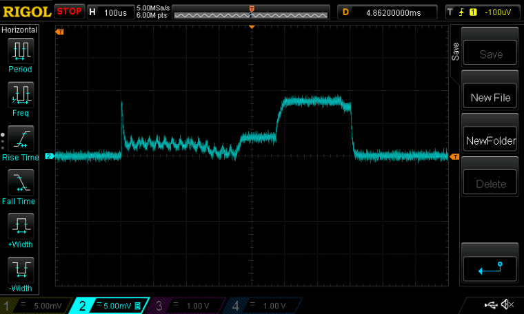
As you can see, there is now about a 370us warm-up time at the beginning for the High Frequency oscillator to come up to speed before the RX cycle can be started. Then it takes about 100us for the receiver to warm-up to RXIDLE. From there it finally achieves about 200us of actual productive RX time. Then everything powers down until the end of the 100ms cycle, after which it all repeats again. To conserve energy, all this is managed by the PPI while the MCU sleeps.
Scale: 1mv=1maI think this is about as energy efficient as it's ever going to get, short of chipping away at the number of bits in the frame/packet size, as I indicated earlier.
-
@NeverDie said in nRF5 Bluetooth action!:
@Mike_Lemo said in nRF5 Bluetooth action!:
Did anyone managed to get two NRF52832 to connect to each other with the arduino IDE and communicate?Yes. @d00616's demo code will do this.
I don't know the answers to the rest of your questions, because I don't use the ST.
Any idea how I reach to this code?
Also you say you don't experience any issues with I2C like that?
-
@Mike_Lemo said in nRF5 Bluetooth action!:
Any idea how I reach to this code?
Yes, it's all explained in detail by @d00616 here: https://www.openhardware.io/view/376/MySensors-NRF5-Platform
Also you say you don't experience any issues with I2C like that?
Haven't tried I2C on this platform yet. I'd be very surprised if it didn't work though, as that's ARM Cortex M4 stuff, which is well vetted. i.e. no real dependency on anything Nordic per se.
-
@NeverDie said in nRF5 Bluetooth action!:
@Mike_Lemo said in nRF5 Bluetooth action!:
Any idea how I reach to this code?
Yes, it's all explained in detail by @d00616 here: https://www.openhardware.io/view/376/MySensors-NRF5-Platform
Also you say you don't experience any issues with I2C like that?
Haven't tried I2C on this platform yet. I'd be very surprised if it didn't work though, as that's ARM Cortex M4 stuff, which is well vetted. i.e. no real dependency on anything Nordic per se.
The link you attached links me to a getting started page not wireing two nrf's together
-
@Mike_Lemo said in nRF5 Bluetooth action!:
The link you attached links me to a getting started page not wireing two nrf's together
Your question was ambiguous. When you said "connect" I just assumed you meant wirelessly connect.
Sorry, I can't help you. Seems like @scalz has gotten I2C to work with it though, but more likely for reading a TH sensor than for the purpose of wiring two nRF52832's. Still, that would prove that it works. If you know the I2C protocol, it shouldn't be hard to go from that to wiring two nRF52832's together.
-
@NeverDie said in nRF5 Bluetooth action!:
I think this is about as energy efficient as it's ever going to get, short of chipping away at the number of bits in the frame/packet size, as I indicated earlier.
I also measured the current between the peaks shown in the scopeshot. By increasing the period between listens, I was able to do the measurement using a uCurrent Gold. Doing so, I found that the current drawn was 10.7ua using the Low Frequency crystal oscillator, and 11.2ua using the Low Frequency RC oscillator. I'm now sure how to square that with some of the earlier measurements I had taken with the nRF52832 sleeping using the MySensors sleep routine, as those measurements came out to about 6ua. Perhaps the difference is the extra current required to run the PPI in this configuration? With neither oscillator configured, and no PPI, it measures, as I said earlier, at 2.2ua, which is close to what the datasheet predicts.
-
@Mike_Lemo said in nRF5 Bluetooth action!:
@NeverDie said in nRF5 Bluetooth action!:
@Mike_Lemo said in nRF5 Bluetooth action!:
Any idea how I reach to this code?
Yes, it's all explained in detail by @d00616 here: https://www.openhardware.io/view/376/MySensors-NRF5-Platform
Also you say you don't experience any issues with I2C like that?
Haven't tried I2C on this platform yet. I'd be very surprised if it didn't work though, as that's ARM Cortex M4 stuff, which is well vetted. i.e. no real dependency on anything Nordic per se.
The link you attached links me to a getting started page not wireing two nrf's together
Yes I did mean wirelessly like central and peripherial connection... Is that supported?
-
I'm sorry, but I can't help you any more than I already have.
-
@NeverDie said in nRF5 Bluetooth action!:
I think this is about as energy efficient as it's ever going to get
Epilog: I ran it overnight on a 10F capacitor, and it dropped only 0.011v per hour. I'm very happy with that, considering it's listening every 100ms as to whether or not it has received a packet.

-
@d00616 Your posting says,
At the moment on Arduino, there is no definition of various OUTPUT modes. If you want to access all nRF5 output modes, you have to use hwPinMode and the OUTPUT_... macro.
Exactly which macro would that be? It looks to me as though what most users will want is the function nrf5_pinmode(..,..), which appears to do all the actual work. Is that right? It is defined in the file nrf5_wiring_digital.c.
Meanwhile, hwPinMode appears to be merely a straight pass-through for pinMode:
void hwPinMode(uint8_t pin, uint8_t mode)
{
  pinMode(pin, mode);
}
-
Where is it possible to find a reference schematic for using the NTF52832 E73-2G4M04S module with NFC?
not much is being given in the datasheet not even where the NFC pins go.
-
@Mike_Lemo said in nRF5 Bluetooth action!:
Where is it possible to find a reference schematic for using the NTF52832 E73-2G4M04S module with NFC?
not much is being given in the datasheet not even where the NFC pins go.Please look into the product documentation:
http://infocenter.nordicsemi.com/topic/com.nordic.infocenter.nrf52832.ps.v1.1/nfc.html?cp=2_1_0_41_8#concept_ryw_4hk_1s@NeverDie said in nRF5 Bluetooth action!:
At the moment on Arduino, there is no definition of various OUTPUT modes. If you want to access all nRF5 output modes, you have to use hwPinMode and the OUTPUT_... macro.
Exactly which macro would that be? It looks to me as though what most users will want is the function nrf5_pinmode(..,..), which appears to do all the actual work. Is that right? It is defined in the file nrf5_wiring_digital.c.
hwPinMode allows to define platform specific PinMode replacements. Code may be portable. This is the reason pointing to nrf5_pinmode().
nrf5_pinmode() has a little bit more functionality than the original pinmode function.
Meanwhile, hwPinMode appears to be merely a straight pass-through for pinMode:
void hwPinMode(uint8_t pin, uint8_t mode)
{
pinMode(pin, mode);
}This disables the capability using nRF5 specific pin modes with the MySensors API.
-
@d00616 said in nRF5 Bluetooth action!:
@Mike_Lemo said in nRF5 Bluetooth action!:
Where is it possible to find a reference schematic for using the NTF52832 E73-2G4M04S module with NFC?
not much is being given in the datasheet not even where the NFC pins go.Please look into the product documentation:
http://infocenter.nordicsemi.com/topic/com.nordic.infocenter.nrf52832.ps.v1.1/nfc.html?cp=2_1_0_41_8#concept_ryw_4hk_1s@NeverDie said in nRF5 Bluetooth action!:
At the moment on Arduino, there is no definition of various OUTPUT modes. If you want to access all nRF5 output modes, you have to use hwPinMode and the OUTPUT_... macro.
Exactly which macro would that be? It looks to me as though what most users will want is the function nrf5_pinmode(..,..), which appears to do all the actual work. Is that right? It is defined in the file nrf5_wiring_digital.c.
hwPinMode allows to define platform specific PinMode replacements. Code may be portable. This is the reason pointing to nrf5_pinmode().
nrf5_pinmode() has a little bit more functionality than the original pinmode function.
Meanwhile, hwPinMode appears to be merely a straight pass-through for pinMode:
void hwPinMode(uint8_t pin, uint8_t mode)
{
pinMode(pin, mode);
}This disables the capability using nRF5 specific pin modes with the MySensors API.
I'm talking about the module it's self isn't there a reference schematic for that? I see there are some component in there but else do I have to add to make this work?
-
@Mike_Lemo said in nRF5 Bluetooth action!:
Yes I did mean wirelessly like central and peripherial connection... Is that supported?
You're mixing things maybe. You're talking about bluetooth. that's not Mysensors

But if you want to get a connection between two nrf52832 or nrf52832/nrf24, take a look at d00616 docs.a nrf52 is a nrf52, no matter the module.
So nfc pins (which are fixed) will be the same on every nrf52 you'll find. It can just happen that you get a board where those pins are used for other purpose (then you can't use nfc without little hack).
But regarding the cdebyte modules, these are simply nrf52 with pinout. So no problem here. Just take a look at the nordic link d00616 showed about using nfc.
In case.. pins are P0.09 and P0.10. But you'll need to tune your nfc antenna, and add capacitors. Sparkfun, adafruit have some infos on this as they're selling boards.
-
Also, if you're interested in NFC, the Nordic nRF52832 DK comes with an antenna for it. It would probably be the easiest to use, because a connector for the antenna is already on the board.
-
Yeah but my question was about what is connected in the module and what components I have to use....
Also about the NFC I'm planning to use it with the arduino IDE so just wanted to ask if there is a library for it because the SDK is quite useless in this case as well as the Central peripheral connection.
-
I was able to reduce the active listen period to about 100us:
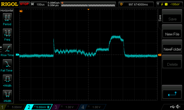
Now listening every 100ms yields a 10F supercap voltage measured decline of just 9mv per hour. i.e. a decline of 0.108v by the end of 12 hours.
-
@Mike_Lemo said in nRF5 Bluetooth action!:
Also about the NFC I'm planning to use it with the arduino IDE so just wanted to ask if there is a library for it because the SDK is quite useless in this case as well as the Central peripheral connection.
Now there is a second port of arduino to nRF52. This includes some libraries, like NFC, but they using the SDK. MySensors is currently not ready for this arduino-port.
-
@NeverDie said in nRF5 Bluetooth action!:
Now listening every 100ms yields a 10F supercap voltage measured decline of just 9mv per hour. i.e. a decline of 0.108v by the end of 12 hours.
Great job. If I'm not wrong the method allows nearly 1 year of listening time with a CR2032.
-
@Mike_Lemo your best bet is to "convert" the module to Arduino Primo and use the NFC libraries developed for it.
d00616 gave you the link to the arduino org github. Pls. note that Primo core generates a merged softdevice+sketch hex so you should locate it in the Temp folder and upload.
-
Here's a very simple OPEN/CLOSE remote control I was able to quickly throw together using my small prototyping board:
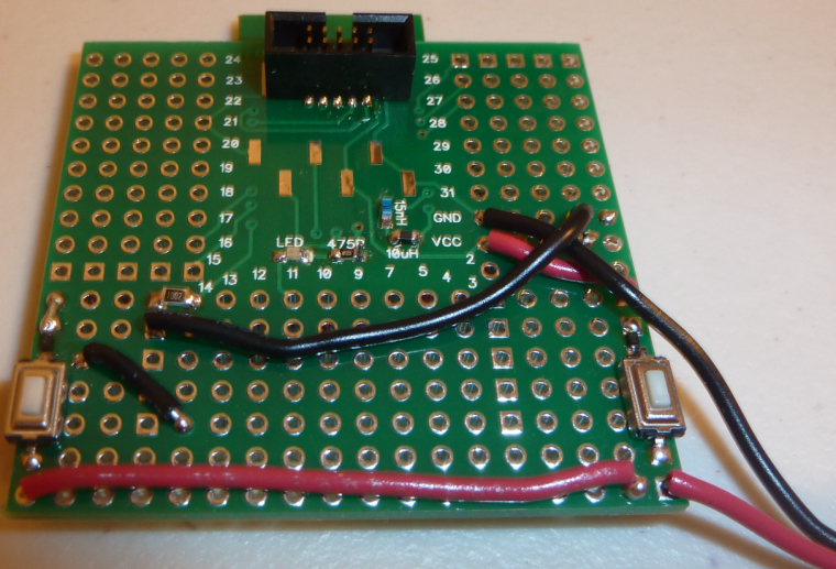
It required only two buttons, a diode, a resistor, and (obviously) some wire. When not in use, everything is powered 100% OFF to save the most energy possible. So, pushing either button powers it ON, at which point it rapidly determines which button was pushed and then sends the corresponding packet to the receiver. From the standpoint of human perception, it all appears to happen instantly.
-
This is how the next version of the protoboard will look:
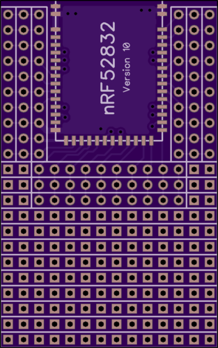
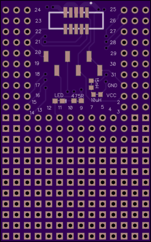
-
Interestingly, it looks as though Arduino is suggesting/recommending users to use the regular Arduino Primo to program the Arduino Primo Core (i.e. the wearable).
-
@NeverDie is this SWD?
-
@Toyman said in nRF5 Bluetooth action!:
@NeverDie is this SWD?
I don't have either the Primo or the Primo Core, so I can't say for sure. However, I presume so.
-
@Mike_Lemo
This sounds more like an EMC issue.
The connected ST Link filters some disturbance at the i2c lines, and when it's not connected, the disturbance corrupts the signals.
Try connecting capacitors from the i2c lines to ground. I'd start with 100pF each.
May also be a power supply issue. Did you connect the st-link's 3.3V line to the board?
-
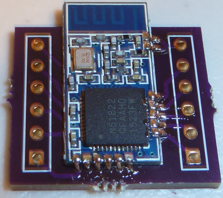
Here's the small budget nRF51 soldered to the breakout board that I had linked earlier above:
-
I have the RTC running off the low frequency internal RC, because I don't see a crystal oscillator on the module. I have it blinking an LED now and sending text to the serial port, which I'm able to read on the serial console.
At least so far, all is good.

-
@NeverDie said in nRF5 Bluetooth action!:
Here's a very simple OPEN/CLOSE remote control I was able to quickly throw together using my small prototyping board:

It required only two buttons, a diode, a resistor, and (obviously) some wire. When not in use, everything is powered 100% OFF to save the most energy possible. So, pushing either button powers it ON, at which point it rapidly determines which button was pushed and then sends the corresponding packet to the receiver. From the standpoint of human perception, it all appears to happen instantly.Hello @NeverDie, could you please share the code for this ?
I'd like to adapt and test it on a reprogrammed nrf51822 beacon that I just received.
-
@Nca78
I can, but it wouldn't be proper "mysensors" code, because mysensors code has a 5-10 second power-up delay. So, for that reason, it's using radiohead instead. Do you still want it anyway?
-
@NeverDie said in nRF5 Bluetooth action!:
@Nca78
I can, but it wouldn't be proper "mysensors" code, because mysensors code has a 5-10 second power-up delay. So, for that reason, it's using radiohead instead. Do you still want it anyway?Ah I see, probably still interesting to see, please share anyway

-
I am trying to reprogram a commercial nrf51 module. Under "commerical" I mean "not from aliexpress", but installed in "smart" bluetooth socket.
I can connect to it with Black Magic Probe just fine, but after mass_erase, BMP reports 0xfffffffe instead of usual 0xffffffff, meaning something is lef behind. That prohibits reflashing of softdevice BUT I can load "plain" skethes that do not require softdevice
I ASSUME the module has some kind of write protection and/or UICR registers set that are not erased with BMP mass+erase command.
I've tried to load d0016 uuicr clearing sketch, It loads fine, but I've still got 0xfffffffe after masserase.
So what's the proper way to really completely erase the module?
I have nrf52 dk that I tried to use as a programmer but it didn't worked.
-
@Nca78 said in nRF5 Bluetooth action!:
@NeverDie said in nRF5 Bluetooth action!:
@Nca78
I can, but it wouldn't be proper "mysensors" code, because mysensors code has a 5-10 second power-up delay. So, for that reason, it's using radiohead instead. Do you still want it anyway?Ah I see, probably still interesting to see, please share anyway

Here it is, warts and all:
0_1506603795796_remote_control_v031.zip
It works, but it's just hastily improvised throw-away code, so I made no attempt to polish it. i.e. For anyone reading this: It is very definitely not demo code.
-
@NeverDie This may be old news but I will throw it out anyway. The Reset pin on the nRF52 series is both a GPIO and RESET line (one or the other) . This is not a dedicated Reset however and the application must define that pin as RESET. This is the only pin that can be defined as reset. The Datasheet describes this as well.
-
@Toyman What is the make and model of the module. You can use the nRF52-DK to erase the device. P20 is a ease access to the programming pins on that board. You need to power up the module, run the VDD from the module back to the dev kit , P20, Pin2. Hook up the SWDIO lines to Pin3 and the SWDCLK to Pin4. and Ground, Pin8. As reset is not hardwired you don't have to hook that up unless you want to (Pin7. .  You can use nRFJPROG to exersise the J-Link (Segger). This is found in the downloadable tools on the Nordic site. BTW - I have no problem using J-Link Commander version 6.20c with the nRF52-DK with the nRF52832 mounted. I hope this helped.
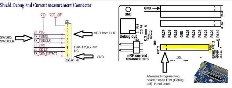
-
@Jokgi said in nRF5 Bluetooth action!:
@NeverDie This may be old news but I will throw it out anyway. The Reset pin on the nRF52 series is both a GPIO and RESET line (one or the other) . This is not a dedicated Reset however and the application must define that pin as RESET. This is the only pin that can be defined as reset. The Datasheet describes this as well.
Yes, and thanks to @d00616's work, RESET can also be enabled/disabled from the Tools menu of the arduino IDE if using myNRF5Board as the board definition.
-
I just now compared the transmission range and packet loss of the cheap nRF51822 to the Ebyte nRF52832. I expected that the Ebyte, with its bigger and fancier antenna, to mop the floor with the nRF51822, but I was surprised to find that they actually seem fairly comparable (at least in my informal, off-the-cuff testing). So, if you have a sensor that's mostly transmission oriented, like, say, a TH sensor, the smaller and cheaper nRF51822 is maybe worth considering.
-
@NeverDie said in nRF5 Bluetooth action!:
the smaller and cheaper nRF51822 is maybe worth considering.
That is interesting. What sort of range where you getting?
Do you have the 840 dev kit? If so, can you measure range on that guy? Should be 10x I would think.
-
Around 30 feet, through some walls, but at 2mbps. I realize that's not very far, but even so the measured packet loss (informal testing) is pretty high at that speed. I can see why most people default to 250kbps instead.
I don't have the 840 dev kit yet, mostly because I don't see anyother 840 modules on the market right now.
-
What's a good initial value to use for DATAWHITEIV, if doing data whitening?
-
@Jokgi Thanks. That's exactly what I did. Flashed successfully but ideally I'd like to find a way to power the module from the DK (I had to use the external power)
Unfortunately, this was the first time when BMP let me down. It just failed to load either softdevice or the sketch hex while Jlink@DK handled it without any problem.
-
@d00616
Which settings are key for ensuring that packets sent by the nRF24 are correctly received by the nRF5? It would be nice to leverage the versions of the nRF24 that have amplified Tx. For sending wake-up packets, I shoudln't need shockburst, and so maybe this will work fairly easily.
-
@NeverDie said in nRF5 Bluetooth action!:
Which settings are key for ensuring that packets sent by the nRF24 are correctly received by the nRF5? It would be nice to leverage the versions of the nRF24 that have amplified Tx.
These are more than settings. You have to set the Radio configuration like in Radio_ESB.cpp, reverse the addresses and handle sending ACK packages by software.
This is a good resource to understand the OTA protocol: https://hackaday.io/project/11942-antenna-diversity-receive-and-transmit/log/39510-shockburst-vs-enhanced-shockburst-nrf24-vs-nrf5x
I can provide a simple example how to use the MySensors transport code without Radio Head. This works for nRF5 and nRF24 modules, but its outside of that what the MY_CORE_ONLY mode is designed for.
#define MY_CORE_ONLY

#ifndef ARDUINO_ARCH_NRF5
#define MY_NODE_ID (1)
#define SND_TO (2)
#else
#define MY_NODE_ID (2)
#define SND_TO (1)
#endif

// Enable debug
#define MY_DEBUG
//#define MY_DEBUG_VERBOSE_RF24
//#define MY_DEBUG_VERBOSE_NRF5_ESB


// RF24_250KBPS RF24_1MBPS RF24_2MBPS
#define MY_RF24_DATARATE (RF24_1MBPS)
// NRF5_250KBPS NRF5_1MBPS NRF5_2MBPS
#define MY_NRF5_ESB_MODE (NRF5_1MBPS)


// Enable and select radio type attached
#ifndef NRF5
#define MY_RADIO_NRF24
#else
#define MY_RADIO_NRF5_ESB
#endif

#include <MySensors.h>

void setup() {
  Serial.begin(115200);

  hwInit();
  transportInit();
  transportSetAddress(MY_NODE_ID);
}

void loop() {
  // Check for packages
  while (transportAvailable()) {
    uint8_t buffer[256];
    uint8_t num = transportReceive(&buffer);
    Serial.print("Data=");
    for (int i=0;i<num;i++) {
      if (buffer[i]<0x10) Serial.print("0");
      Serial.print(buffer[i], HEX);
      Serial.print(" ");
    }
    Serial.println();
  }

  wait(1000);

  // Send data
  transportSend(SND_TO, "abcdefghijklmnopqrstuvwxyzabcdefghijklmnopqrstuvwxyz",32, false);
}
-
@NeverDie said in nRF5 Bluetooth action!:
Yes, and thanks to @d00616's work, RESET can also be enabled/disabled from the Tools menu of the arduino IDE if using myNRF5Board as the board definition.
The reset support isn't complete at the moment. The menu is active, but it has no effect at the moment. I fix this with release 0.2.0.
-
I just received 2 of those little boards.
Ideal for small sensor nodes, I'd say, but not very breadboard friendly.
So I dug out the verowire, and did a little soldering.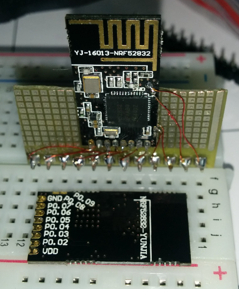
-
@d00616 said in nRF5 Bluetooth action!:
@NeverDie said in nRF5 Bluetooth action!:
Which settings are key for ensuring that packets sent by the nRF24 are correctly received by the nRF5? It would be nice to leverage the versions of the nRF24 that have amplified Tx.
These are more than settings. You have to set the Radio configuration like in Radio_ESB.cpp, reverse the addresses and handle sending ACK packages by software.
This is a good resource to understand the OTA protocol: https://hackaday.io/project/11942-antenna-diversity-receive-and-transmit/log/39510-shockburst-vs-enhanced-shockburst-nrf24-vs-nrf5x
I can provide a simple example how to use the MySensors transport code without Radio Head. This works for nRF5 and nRF24 modules, but its outside of that what the MY_CORE_ONLY mode is designed for.
#define MY_CORE_ONLY

#ifndef ARDUINO_ARCH_NRF5
#define MY_NODE_ID (1)
#define SND_TO (2)
#else
#define MY_NODE_ID (2)
#define SND_TO (1)
#endif

// Enable debug
#define MY_DEBUG
//#define MY_DEBUG_VERBOSE_RF24
//#define MY_DEBUG_VERBOSE_NRF5_ESB


// RF24_250KBPS RF24_1MBPS RF24_2MBPS
#define MY_RF24_DATARATE (RF24_1MBPS)
// NRF5_250KBPS NRF5_1MBPS NRF5_2MBPS
#define MY_NRF5_ESB_MODE (NRF5_1MBPS)


// Enable and select radio type attached
#ifndef NRF5
#define MY_RADIO_NRF24
#else
#define MY_RADIO_NRF5_ESB
#endif

#include <MySensors.h>

void setup() {
  Serial.begin(115200);

  hwInit();
  transportInit();
  transportSetAddress(MY_NODE_ID);
}

void loop() {
  // Check for packages
  while (transportAvailable()) {
    uint8_t buffer[256];
    uint8_t num = transportReceive(&buffer);
    Serial.print("Data=");
    for (int i=0;i<num;i++) {
      if (buffer[i]<0x10) Serial.print("0");
      Serial.print(buffer[i], HEX);
      Serial.print(" ");
    }
    Serial.println();
  }

  wait(1000);

  // Send data
  transportSend(SND_TO, "abcdefghijklmnopqrstuvwxyzabcdefghijklmnopqrstuvwxyz",32, false);
}
I tried compiling it using the Arduino Windows IDE, but for some reason it complains about not finding a whole litany of .h files: socket.h, w5100.h, netdb.h.... Does mysensors.h really need to drag in all of those .h files, even if only indirectly? Or, if there's an easy way to make it find them, what is it?
-
@NeverDie said in nRF5 Bluetooth action!:
I tried compiling it using the Arduino Windows IDE, but for some reason it complains about not finding a whole litany of .h files: socket.h, w5100.h, netdb.h.... Does mysensors.h really need to drag in all of those .h files, even if only indirectly? Or, if there's an easy way to make it find them, what is it?
I can compile it with Linux. What are missing is part of the Ethernet library. I don't know why it's included in you build.
-
I just now upgraded to the current release of the mysensors development library, and the compile problem went away.
 So, if anyone else encounters the same problem, I recommend doing that.
-
@NeverDie said in nRF5 Bluetooth action!:
I just now upgraded to the current release of the mysensors development library, and the compile problem went away. So, if anyone else encounters the same problem, I recommend doing that.
Sorry. I have forgotten my uncommited changes. At the moment, you have to start the HFCLK in the CORE_ONLY mode. This is done in hwInit() later.
-
@d00616 said in nRF5 Bluetooth action!:
@NeverDie said in nRF5 Bluetooth action!:
I just now upgraded to the current release of the mysensors development library, and the compile problem went away. So, if anyone else encounters the same problem, I recommend doing that.
... At the moment, you have to start the HFCLK in the CORE_ONLY mode. ...
Do you have a revised sketch which does that? I tried running the sketch you gave above on an nRF52 DK, but it immediately goes into a boot-loop, wherein in keeps rebooting itself, over and over and over again.
-
@NeverDie said in nRF5 Bluetooth action!:
I tried running the sketch you gave above on an nRF52 DK, but it immediately goes into a boot-loop, wherein in keeps rebooting itself, over and over and over again.
I just now tried running it on a pro-mini using a nRF24, and it also gets into a boot-loop.
-
@NeverDie said in nRF5 Bluetooth action!:
I just now tried running it on a pro-mini using a nRF24, and it also gets into a boot-loop.
Please replace wait() with delay(). This is an issue in the transport code, which is triggered while sleep() or wait() is executed.
-
@d00616 said in nRF5 Bluetooth action!:
@NeverDie said in nRF5 Bluetooth action!:
I just now tried running it on a pro-mini using a nRF24, and it also gets into a boot-loop.
Please replace wait() with delay(). This is an issue in the transport code, which is triggered while sleep() or wait() is executed.
OK, made that change, and it no longer boot-loops.
However, neither node appears to be receiving anything from the other.
Please advise.
-
@d00616
Since the original code didn't work, I upgraded it somewhat to give a larger Rx window. However, it still doesn't work:#define MY_CORE_ONLY #ifndef ARDUINO_ARCH_NRF5 #define MY_NODE_ID (1) #define SND_TO (2) #else #define MY_NODE_ID (2) #define SND_TO (1) #endif // Enable debug #define MY_DEBUG //#define MY_DEBUG_VERBOSE_RF24 //#define MY_DEBUG_VERBOSE_NRF5_ESB // RF24_250KBPS RF24_1MBPS RF24_2MBPS #define MY_RF24_DATARATE (RF24_1MBPS) // NRF5_250KBPS NRF5_1MBPS NRF5_2MBPS #define MY_NRF5_ESB_MODE (NRF5_1MBPS) // Enable and select radio type attached #ifndef NRF5 #define MY_RADIO_NRF24 #else #define MY_RADIO_NRF5_ESB #endif #include <MySensors.h> void setup() { Serial.begin(115200); Serial.println("Starting...."); Serial.print("MY_NODE_ID="); Serial.println(MY_NODE_ID); Serial.print("SND_TO="); Serial.println(SND_TO); hwInit(); transportInit(); transportSetAddress(MY_NODE_ID); } uint32_t theTime=0; uint32_t loopCounter=0; void loop() { // Check for packages while ((millis()-theTime)<1000) { while (transportAvailable()) { uint8_t buffer[256]; uint8_t num = transportReceive(&buffer); Serial.print("Data="); for (int i=0;i<num;i++) { if (buffer[i]<0x10) Serial.print("0"); Serial.print(buffer[i], HEX); Serial.print(" "); } Serial.println(); } } theTime=millis(); //delay(1000); Serial.print(loopCounter++); Serial.println(", SENDING: abcdefghijklmnopqrstuvwxyzabcdefghijklmnopqrstuvwxyz"); // Send data transportSend(SND_TO, "abcdefghijklmnopqrstuvwxyzabcdefghijklmnopqrstuvwxyz",32, false); }One node is an nRF24 on a pro mini, and the other is an nRF52832.
-
@NeverDie said in nRF5 Bluetooth action!:
Since the original code didn't work, I upgraded it somewhat to give a larger Rx window. However, it still doesn't work:
Please add this to your setup() function (https://forum.mysensors.org/topic/6961/nrf5-bluetooth-action/985

	// Clock is manged by sleep modes. Radio depends on HFCLK.
	// Force to start HFCLK
	NRF_CLOCK->EVENTS_HFCLKSTARTED = 0;
	NRF_CLOCK->TASKS_HFCLKSTART = 1;
	while (NRF_CLOCK->EVENTS_HFCLKSTARTED == 0)
		;

	// Enable low latency sleep mode
	NRF_POWER->TASKS_CONSTLAT = 1;

	// Enable cache on >= NRF52
#ifndef NRF51
	NRF_NVMC->ICACHECNF = NVMC_ICACHECNF_CACHEEN_Msk;
#endif
At the moment I prepare a new Pull Request fixing this including some small fixes and improvements for nRF5 MCUs. When it's integrated the HFCLK is startet in hwInit().
-
@d00616 is this universal recommendation?
-
@Toyman said in nRF5 Bluetooth action!:
@d00616 is this universal recommendation?
I think you mean to start the HFCLK. This isn't a universal recommendation. At the moment the HFCLK is started in MyMainNRF5.cpp. This file is ignored in CORE_ONLY mode. I moved any initialization code into hwInit().
-
@d00616 said in nRF5 Bluetooth action!:
At the moment I prepare a new Pull Request fixing this including some small fixes and improvements for nRF5 MCUs. When it's integrated the HFCLK is startet in hwInit().
The Pull Request is available: https://github.com/mysensors/MySensors/pull/938
-
@d00616 said in nRF5 Bluetooth action!:
@d00616 said in nRF5 Bluetooth action!:
At the moment I prepare a new Pull Request fixing this including some small fixes and improvements for nRF5 MCUs. When it's integrated the HFCLK is startet in hwInit().
The Pull Request is available: https://github.com/mysensors/MySensors/pull/938
That link lists changes to the files, but it doesn't seem to provide the new files. Or else I'm overlooking where it does?
-
@NeverDie said in nRF5 Bluetooth action!:
That link lists changes to the files, but it doesn't seem to provide the new files. Or else I'm overlooking where it does?
You have to checkout this pull request: https://help.github.com/articles/checking-out-pull-requests-locally/
-
@d00616 said in nRF5 Bluetooth action!:
@NeverDie said in nRF5 Bluetooth action!:
That link lists changes to the files, but it doesn't seem to provide the new files. Or else I'm overlooking where it does?
You have to checkout this pull request: https://help.github.com/articles/checking-out-pull-requests-locally/
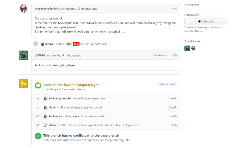
Maybe I need write-access or something? Those instructions refer to a command line, and I just don't see one anywhere.
-
Well, anyway, I added code to start the high frequency clock, and now it seems to work:
#define MY_CORE_ONLY

#ifndef ARDUINO_ARCH_NRF5
#define MY_NODE_ID (1)
#define SND_TO (2)
#else
#define MY_NODE_ID (2)
#define SND_TO (1)
#endif

// Enable debug
#define MY_DEBUG
//#define MY_DEBUG_VERBOSE_RF24
//#define MY_DEBUG_VERBOSE_NRF5_ESB


// RF24_250KBPS RF24_1MBPS RF24_2MBPS
#define MY_RF24_DATARATE (RF24_1MBPS)
// NRF5_250KBPS NRF5_1MBPS NRF5_2MBPS
#define MY_NRF5_ESB_MODE (NRF5_1MBPS)


// Enable and select radio type attached
#ifndef NRF5
#define MY_RADIO_NRF24
#else
#define MY_RADIO_NRF5_ESB
#endif

#include <MySensors.h>
#include <nrf.h>

void setup() {
  Serial.begin(115200);
  Serial.println("Starting....");
  Serial.print("MY_NODE_ID=");
  Serial.println(MY_NODE_ID);
  Serial.print("SND_TO=");
  Serial.println(SND_TO);

  if (MY_NODE_ID==2) {
    NRF_CLOCK->TASKS_HFCLKSTART=1;  //activate the high frequency crystal oscillator
    while ((NRF_CLOCK->EVENTS_HFCLKSTARTED==0)) {};  //wait until high frequency clock start is confirmed
  }


  hwInit();
  transportInit();
  transportSetAddress(MY_NODE_ID);
}

uint32_t theTime=0;
uint32_t loopCounter=0;
void loop() {
  // Check for packages
  while ((millis()-theTime)<1000) {
    while (transportAvailable()) {
      uint8_t buffer[256];
      uint8_t num = transportReceive(&buffer);
      Serial.print("Data=");
      for (int i=0;i<num;i++) {
        if (buffer[i]<0x10) Serial.print("0");
        Serial.print(buffer[i], HEX);
        Serial.print(" ");
      }
      Serial.println();
    }
  }
  theTime=millis();

  //delay(1000);
  Serial.print(loopCounter++);
  Serial.println(", SENDING:  abcdefghijklmnopqrstuvwxyzabcdefghijklmnopqrstuvwxyz");

  // Send data
  transportSend(SND_TO, "abcdefghijklmnopqrstuvwxyzabcdefghijklmnopqrstuvwxyz",32, false);
}
-
@NeverDie said in nRF5 Bluetooth action!:
Maybe I need write-access or something? Those instructions refer to a command line, and I just don't see one anywhere.
You can do this with git on your local machine:
git clone https://github.com/mysensors/MySensors.git
cd MySensors
git fetch origin pull/938/head:pr938
git checkout pr938
-
@d00616
Thanks for trying. That would probably work with a linux machine, but mine is running Windows. I'm surprised there's no easy way to do this from Windows.I guess I'll just wait for the next developers release of mysensors.
-
For anyone else caught in the same limbo as me, here's a more proper update of the earlier example:
#define MY_CORE_ONLY

#ifndef ARDUINO_ARCH_NRF5
#define MY_NODE_ID (1)
#define SND_TO (2)
#else
#define MY_NODE_ID (2)
#define SND_TO (1)
#endif

// Enable debug
#define MY_DEBUG
//#define MY_DEBUG_VERBOSE_RF24
//#define MY_DEBUG_VERBOSE_NRF5_ESB


// RF24_250KBPS RF24_1MBPS RF24_2MBPS
#define MY_RF24_DATARATE (RF24_1MBPS)
// NRF5_250KBPS NRF5_1MBPS NRF5_2MBPS
#define MY_NRF5_ESB_MODE (NRF5_1MBPS)


// Enable and select radio type attached
#ifndef NRF5
#define MY_RADIO_NRF24
#else
#define MY_RADIO_NRF5_ESB
#include <nrf.h>
#endif

#include <MySensors.h>

void setup() {
  Serial.begin(115200);
  Serial.println("Starting....");
  Serial.print("MY_NODE_ID=");
  Serial.println(MY_NODE_ID);
  Serial.print("SND_TO=");
  Serial.println(SND_TO);
  Serial.flush();

  #ifdef ARDUINO_ARCH_NRF5
    NRF_CLOCK->TASKS_HFCLKSTART=1;  //activate the high frequency crystal oscillator
    while ((NRF_CLOCK->EVENTS_HFCLKSTARTED==0)) {};  //wait until high frequency clock start is confirmed
  #endif


  hwInit();
  transportInit();
  transportSetAddress(MY_NODE_ID);
}

uint32_t theTime=0;
uint32_t loopCounter=0;
void loop() {
  // Check for packages
  while ((millis()-theTime)<1000) {
    while (transportAvailable()) {
      uint8_t buffer[256];
      uint8_t num = transportReceive(&buffer);
      Serial.print(loopCounter);
      Serial.print(", RECEIVED=");
      for (int i=0;i<num;i++) {
        if (buffer[i]<0x10) Serial.print("0");
        Serial.print(buffer[i], HEX);
        Serial.print(" ");
      }
      Serial.println();
      Serial.flush();
    }
  }
  theTime=millis();

  //delay(1000);
  Serial.print(loopCounter++);
  Serial.println(", SENDING:  abcdefghijklmnopqrstuvwxyz01234");
  Serial.println();
  Serial.flush();

  // Send data
  transportSend(SND_TO, "abcdefghijklmnopqrstuvwxyz01234",32, false);
}
The serial output shown by the nRF52 is what you would expect:
Starting....
MY_NODE_ID=2
SND_TO=1
0, RECEIVED=61 62 63 64 65 66 67 68 69 6A 6B 6C 6D 6E 6F 70 71 72 73 74 75 76 77 78 79 7A 30 31 32 33 34 00
0, SENDING:  abcdefghijklmnopqrstuvwxyz01234

1, RECEIVED=61 62 63 64 65 66 67 68 69 6A 6B 6C 6D 6E 6F 70 71 72 73 74 75 76 77 78 79 7A 30 31 32 33 34 00
1, SENDING:  abcdefghijklmnopqrstuvwxyz01234

2, RECEIVED=61 62 63 64 65 66 67 68 69 6A 6B 6C 6D 6E 6F 70 71 72 73 74 75 76 77 78 79 7A 30 31 32 33 34 00
2, SENDING:  abcdefghijklmnopqrstuvwxyz01234

3, RECEIVED=61 62 63 64 65 66 67 68 69 6A 6B 6C 6D 6E 6F 70 71 72 73 74 75 76 77 78 79 7A 30 31 32 33 34 00
3, SENDING:  abcdefghijklmnopqrstuvwxyz01234
However, the serial output of the pro mini often seems to include a 1-byte packet:
Starting....
MY_NODE_ID=1
SND_TO=2
0, RECEIVED=61 62 63 64 65 66 67 68 69 6A 6B 6C 6D 6E 6F 70 71 72 73 74 75 76 77 78 79 7A 30 31 32 33 34 00
0, SENDING:  abcdefghijklmnopqrstuvwxyz01234

1, RECEIVED=61 62 63 64 65 66 67 68 69 6A 6B 6C 6D 6E 6F 70 71 72 73 74 75 76 77 78 79 7A 30 31 32 33 34 00
1, RECEIVED=61 62 63 64 65 66 67 68 69 6A 6B 6C 6D 6E 6F 70 71 72 73 74 75 76 77 78 79 7A 30 31 32 33 34 00
1, SENDING:  abcdefghijklmnopqrstuvwxyz01234

2, RECEIVED=41
2, RECEIVED=61 62 63 64 65 66 67 68 69 6A 6B 6C 6D 6E 6F 70 71 72 73 74 75 76 77 78 79 7A 30 31 32 33 34 00
2, SENDING:  abcdefghijklmnopqrstuvwxyz01234

3, RECEIVED=41
3, RECEIVED=61 62 63 64 65 66 67 68 69 6A 6B 6C 6D 6E 6F 70 71 72 73 74 75 76 77 78 79 7A 30 31 32 33 34 00
3, SENDING:  abcdefghijklmnopqrstuvwxyz01234

4, RECEIVED=47
4, RECEIVED=61 62 63 64 65 66 67 68 69 6A 6B 6C 6D 6E 6F 70 71 72 73 74 75 76 77 78 79 7A 30 31 32 33 34 00
4, SENDING:  abcdefghijklmnopqrstuvwxyz01234

5, RECEIVED=46
5, RECEIVED=61 62 63 64 65 66 67 68 69 6A 6B 6C 6D 6E 6F 70 71 72 73 74 75 76 77 78 79 7A 30 31 32 33 34 00
5, SENDING:  abcdefghijklmnopqrstuvwxyz01234

6, RECEIVED=47
6, RECEIVED=61 62 63 64 65 66 67 68 69 6A 6B 6C 6D 6E 6F 70 71 72 73 74 75 76 77 78 79 7A 30 31 32 33 34 00
6, SENDING:  abcdefghijklmnopqrstuvwxyz01234
Is that a bug?
-
@NeverDie said in nRF5 Bluetooth action!:
Thanks for trying. That would probably work with a linux machine, but mine is running Windows. I'm surprised there's no easy way to do this from Windows.
I guess I'll just wait for the next developers release of mysensors.This depends on Git installed not on Linux. The Pull Request is now into the developer branch.
@NeverDie said in nRF5 Bluetooth action!:
However, the serial output of the pro mini often seems to include a 1-byte packet:
...
Is that a bug?This is the RSSI value, which is send back as ACK payload. I check what's the best way to deal with.
-
Good news. Thanks to the work of @d00616 on making the ESB transport available, I'm getting very good range using the nRF52832 as a receiver and a pro mini with an inexpensive power amplified nRF24 as the sender, all at 2mbps.
 Not sure if there are yet power amplified nRF52832 available (?), but if not, this does the business.
-
One thing I do notice though is that the amount of time it takes to send a packet from an nRF24L01 using this ESB transport is pretty long: about 27ms passes between sending one packet and the next packet, and that's running on an ESP8266, which is pretty fast.
-
Looking at the nRF24L01 datasheet (file:///C:/Users/CoolerMaster/Downloads/nRF24L01_Product_Specification_v2_0%20(3).pdf), it appears that one simply needs to keep the TX FIFO full, and the radio will then send things as fast as it can (which should be a lot faster than 27ms). So, I'll give that a try.
-
Oddly enough, in the current mysensors-development release, it takes even longer: 97ms between packets.
-
@NeverDie isn't it because quality of the radio link is bad, and it needs to send each packet many times while waiting for the ACK between each sending ?
I'm not sure what/how you measure but if you have many packets in your TX FIFO the next packet is processed only when first packet is acknowledged and removed from FIFO, so if radio link is bad the delays of retransmission will add up while processing the TX FIFO and last packet will be sent only after a "long" delay.When an ACK is successfully received from a PRX, it implies that the payload was successfully received and added to the PRX's RX FIFO, the successfully transmitted packet will be removed from the TX FIFO so that the next packet in the FIFO can be transmitted.
-
@NeverDie check out a Colorado company "Notwired". They have a 832 with a PA however I believe the PA is controlled by the softdevice. Check it out as there may be another way to contol it.
-
@NeverDie said in nRF5 Bluetooth action!:
Looking at the nRF24L01 datasheet (file:///C:/Users/CoolerMaster/Downloads/nRF24L01_Product_Specification_v2_0%20(3).pdf), it appears that one simply needs to keep the TX FIFO full, and the radio will then send things as fast as it can (which should be a lot faster than 27ms). So, I'll give that a try.
If "noACK" is enabled, each packet is send 15 times, which consumes ~27ms. Both NRF24 and NRF5 do the same here.
-
Well, there are these:
https://www.aliexpress.com/item/PTR5618PA-Nordic-nRF52832-Module-PA-module-BLE-4-0-Module-Free-shipping/32761051086.html?spm=2114.search0104.3.8.MXhqTf&ws_ab_test=searchweb0_0,searchweb201602_4_10152_10065_10151_10130_5560016_10068_10344_10342_10343_10340_10341_10307_10060_10155_10154_10056_10055_10054_5370016_10059_10534_10533_10532_100031_10099_10338_10339_5580016_10103_10102_10052_10053_10107_10050_10142_10051_10324_10325_9947_10084_513_10083_10080_10082_10081_5590016_10178_10110_10111_10112_10113_10114_143_10312_10314_10078_10079_5570016_10073-9947,searchweb201603_1,ppcSwitch_4&btsid=40a5015f-dcf6-44e1-aba0-2ebedd393fb8&algo_expid=122380a9-0e93-4cf0-b147-38cdf7c5df53-1&algo_pvid=122380a9-0e93-4cf0-b147-38cdf7c5df53
but who knows how well they work. Have to buy 5 just to find out.In time, I'm sure there will be more available with PA's on them.
-
I need to be able to send back-to-back packets from an nRF24L01 in order to guarantee waking up an nRF52832 receiver that's in a "listen mode" but otherwise asleep.
-
@NeverDie have you tried adding ipx antennae to Ebyte module?
Does it help?
-
@Toyman said in nRF5 Bluetooth action!:
@NeverDie have you tried adding ipx antennae to Ebyte module?
Does it help?You need to move the tiny cap for that, not easy

-
@Toyman said in nRF5 Bluetooth action!:
@NeverDie have you tried adding ipx antennae to Ebyte module?
Does it help?Yes, but it made no difference. NCA78's post explains why. So, I guess that connector, which looks so promising, amounts to just marketing bait? i.e. in terms of practicality, it's little more than a decoration? And if so, then which would be a good module to buy if intending to hook up using an ipx? Presumably a module that has only an ipx connector and no other antenna already on it? Which module exactly? I'd like to try it with an eye for use on a gateway.
-
By the way, with the latest library, time between packets is now down to around 1ms. I guess there was a favorable change in the library? I'm now not sure if it's that, or something I may have inadvertantly done while mucking around with it.
-
@Uhrheber said in nRF5 Bluetooth action!:
I just received 2 of those little boards.
Ideal for small sensor nodes, I'd say, but not very breadboard friendly.
So I dug out the verowire, and did a little soldering.
Looks as though the module itself is missing the SW pinouts. Is that what the two wires you soldered near the chip are for?
Suggested Topics
-
Welcome
Announcements • • hek