That's a good point, I missed that detail in the ds. The sensor is now in service, I'll measure it again when i have a chance. Thanks.
M
manutremo
@manutremo
Posts
-
VEML6075 high sleep consumption -
VEML6075 high sleep consumptionI've been reading the thread here, and decided to open a new one since that one is old, and there were no reports of the consumption being fixed.
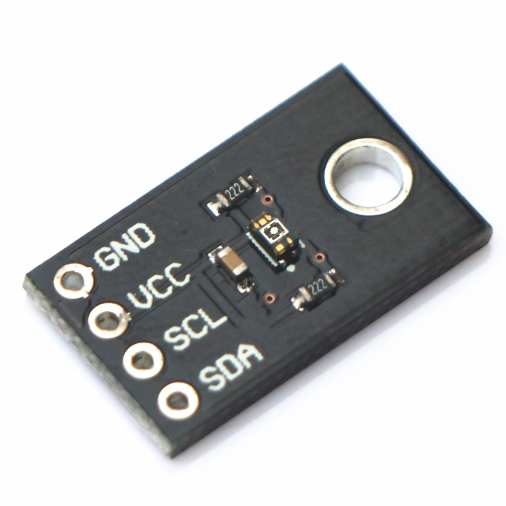
I'm in the same situation regarding consumption of my VEML6075 board being around 50 uA while sleeping, when it should be less than 1 uA according to the datasheet.
My specific board doesn't contain any voltage regulators, just a capacitor and the I2C pullups. Specifically, it's this one:
I'm using the adafruit library but I've tried 3 others with different sleep routines, all with the same result. When active, the consumption is much higher, so the chip is sleeping (sort of) it seems.
Any help on reducing the sleep consumption would be appreciated.
-
Sensebender Gateway RFM69HW Decoupling CapacitorI also had to limit power to 13 dBm; in my case I think the reason is that the board needs more power than what the battery can provide when over that level, but I was never able to prove it.
-
💬 FOTA (Wireless Programming)@mmanzanelli I don't think you can, the Mega has a different memory structure not supported by the present bootloaders.
-
sendTxPowerLevel and sendSignalStrengthHi, I'm interested on using the functions in the post title. I'm running Mysensors 2.2.0., and I have
#define MY_SIGNAL_REPORT_ENABLEDin my sketch.
If I add something like
sendSignalStrength (6);or
sendTxPowerLevel (6);to my sketch, the Arduino compiler complains about undefined references.
What do I need to do to get them working?
Thanks.
-
RFM69HW connection to 2560 Mega Pro boardAnswering to myself... after many tests I decided to start to start working backwards and started to discard assumptions... finally I discarded :
I know that Mega pins are 5v and in theory RFM69 are 3.3v, but I have more sensors installed in a similar setup with mini Pro 5v and Nano boards that work perfectly.
So I fit a ttl levels shifter between the Mega Pro and the RFM69 and it started to work right away.
It looks like AT328 and AT2560 have different levels of sensitivity as of being able to interpret 3.3v correctly as a "1". Interestingly, I checked the datasheets for both chips and the specification is the same, min 0.6Vcc volts, so anything over 3v should be interpreted as a "1"... go see...
As a final detail, I was able to use a 4way ttl shifter since the MISO line doesn't need to be shifted, which left me with MOSI, SCK, SS and INT. Credit to this forum page for this:
I can also confirm that pin D2 on these boards is connected to INT0 as standard... I don't know why the pinout diagram indicates something different.
I hope this helps others.
-
RFM69HW connection to 2560 Mega Pro boardHi,
I'm building a sensor using a Robotdyn Mega Pro board.
[https://robotdyn.com/mega-2560-pro-mini-atmega2560-16au.html](link url)
The pinout of this board is here:
My network uses RFM69 antennas.
My connections are:
MISO 50
MOSI 51
SCK 52
SS 53
DIO00 2Power is connected to 3.3v line. I know that Mega pins are 5v and in theory RFM69 are 3.3v, but I have more sensors installed in a similar setup with mini Pro 5v and Nano boards that work perfectly.
I have also tried two different radios to discard hardware issues.
On start my sketch shows:
3 TSM:INIT
4 TSF:WUR:MS=3000
106 !TSM:INIT:TSP FAIL
108 TSM:FAIL:CNT=1
109 TSM:FAIL:DIS
My concern is that pinout diagrams for "normal" Mega boards show that pin D2 is assigned to INT0, while the pinout for this board linked above indicates that pin D2 is assigned to INT4.
In view of this, I have tried adding the following defines with no success:
#define MY_RFM69_IRQ_PIN 2
#define MY_RFM69_IRQ_NUM 0
I have tried all numbers from 0 to 5 for MY_RFM69_IRQ_NUM.
I also tried pins 18 and 19. I can't use 20 and 21 since I'm using I2C comms.
No matter what I try, I'm still getting the same error.
I searched through the forum and on the inet with no success.
I'd really appreciate if someone could point me in the right direction... thanks!
-
Not working serial gateway connecting sensorIt looks like your sensor is not getting a proper id. There are quite a number of things that coiuld be causing this. Is your gateway connected to a controller?
-
💬 Soil Moisture SensorHi @atzohy
The info in the page is confusing. The small board between the sensor and the arduino is an on-off level switcher. It provides a digital binary singnal so can't be connected to an analog pin on the arduino.
If you wish to measure the moisture level with an analogic scale, you need to eliminate that board and then use a voltage divider and an analog pin. The sketch will be also different. Everything in explained above in the thread.
You may want to read the full thread and then don't hesitate to come back with your questions.
-
Sparkfun8266 Wifi Shield + Arduino Due = WiFi Gateway@zachflem There are no ESP based boards wich such a high number of GPIOs that I know of. But there are some MEGA + ESP boards out there. I'm not sure they would work with Mysensors but may want to have a look.
https://robotdyn.com/mega-wifi-r3-atmega2560-esp8266-flash-32mb-usb-ttl-ch340g-micro-usb.html
https://www.instructables.com/id/Arduino-MEGA-2560-With-WiFi-Built-in-ESP8266/
-
Sparkfun8266 Wifi Shield + Arduino Due = WiFi GatewayUps yes I didn't realize that board won't work.
I'm using a Wemos D1 R2 with support for OTA firmwar updates. I can share the code if you 're interested.
-
Sparkfun8266 Wifi Shield + Arduino Due = WiFi Gateway@zachflem Be sure that the #define is in capitals:
#define MY_GATEWAY_W5100Otherwise it won't be correctly used by the compiler.
-
Sensebender/Dualoptiboot OTA HowTo in Mysensors@scalz Mycontroller works fine, I just tested it with Dualoptiboot and last package version (ask in the forum).
-
RFM69(H)W Arduino Mini Pro Shield to offer@jlaraujo 3 or 4 if possible
-
RFM69(H)W Arduino Mini Pro Shield to offerHi, I'm interested in getting some of those. They are right on time for some new developments I'd like to run over the summer. Final number depending on total number of interested colleagues.
Many thanks for your generosity but I'm willing to pay for them if you want.
Great contribution, many thanks!!!
-
💬 Soil Moisture Sensor@รอเร-อ I have resistive sensors (YL-69 type) both indoors and outdoors. Both have been working correctly for months now. I'm using a direct-reverse polarization sketch to minimize corrosion and it seems to work well. What I found to be very important in outdoors sensors is the isolation of the connector between the probe and the cable; if rain water or watering stays into there, they tend to corrode and their resistance increases, therefore fooling the sensor into thinking that the soil is drier than it really is. I have a couple of capacitive sensors somewhere but haven't felt the need to try them since the resistive ones are working well.
-
Z-wave question@raptorjr said in Z-wave question:
@manutremo I do mention Domiticz several times 😉
OMG either I read too fast or my eyes are going really bad...
Either way - the response to your last question is no, devices can't be grouped in the Devices page... this is probably one of the most requested features but... just not there yet.
For the first question - the quick answer is those devices are normal and you may just ignore them; some of them are there as placeholders for future development. For a more detailed answer, just do a search and you should find the answer without having to interface with anyone... I'd send a link to the response but I don't have it readily available.
-
Z-wave question@raptorjr You don't mention it but I guess you are using Domoticz. I would suggest you ask the same questions on their forum; the first and third questions are answered there.
Regarding a zwave water proof and cold proff switch, the "normal" ones (fibaro, neo coolcam, aeolabs, etc) seem to work well in cold weather, and it all depends on at which temp their battery stops providing enough juice. Regarding water proof, I don't recall having seen any, but a search on ebay or aliexpress might reveal some. As a last resort, you can always wrap them on kitchen plastic film; I do that with some of my mysensors equipment and it works very well.
-
Serial.print and battery powered pro mini@peerv I don't use one of those "red" adapters but mine does the same and it seems to be no problem. Just test it, at worst case there might be some communication problem but that's all and I don't think it should even actually happen.
-
Serial.print and battery powered pro mini@peerv do not connect the vcc pin. Gnd might be necessary to keep the reference common. Keep in mind that your usb will expect to see logic levels related to 5v, so if your arduino is 3.3v you might need a logic level converter.