Small wall outlet sensor node
-
I've created this to have easiest way to establish environment monitoring across the house
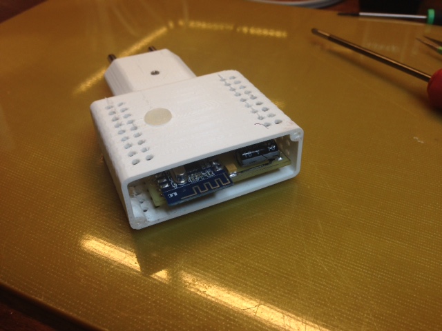
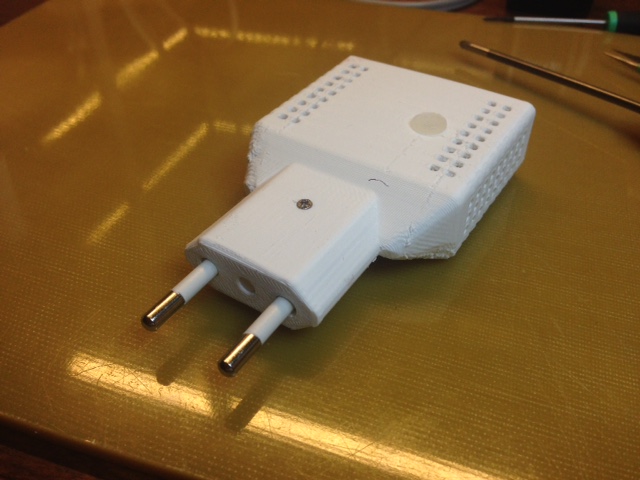
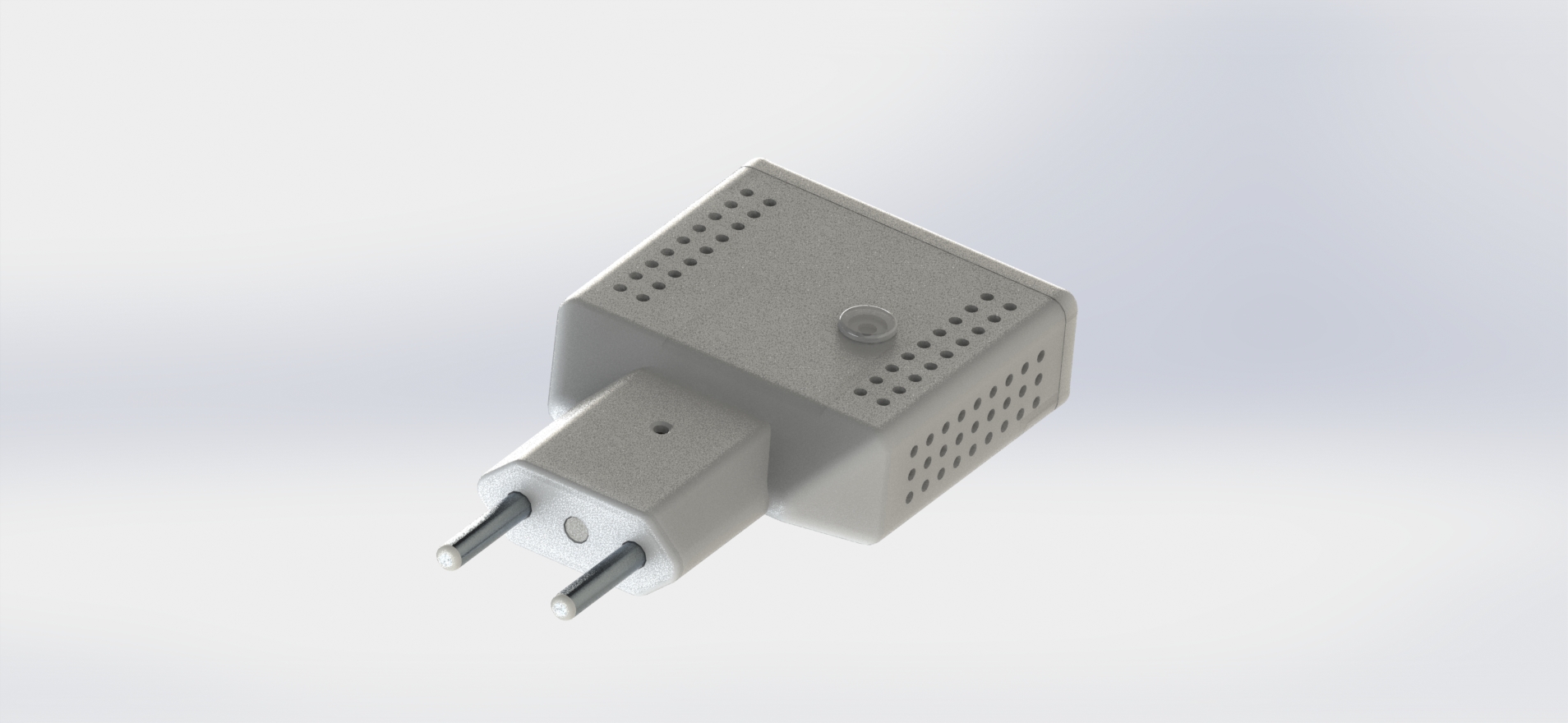
the idea is to have a wall outlet type plug with everything on board
and I like to do small things
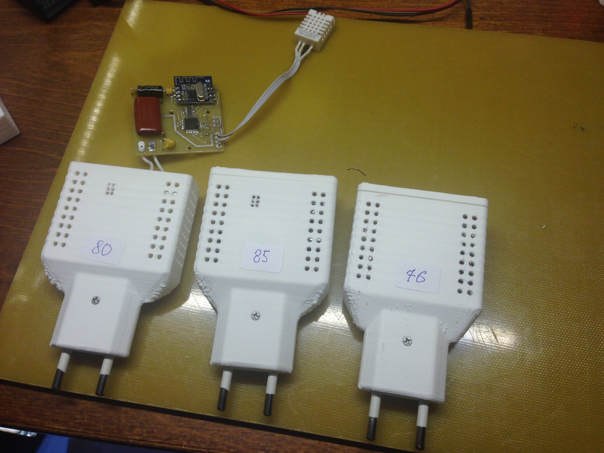
The board is less than 50 x 50 mm
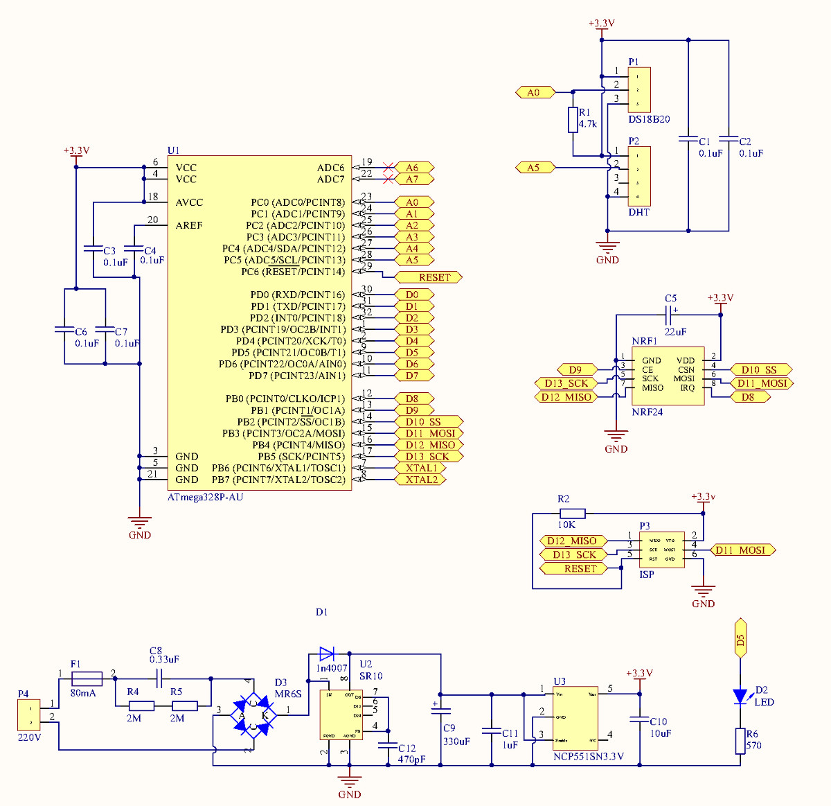
It contains AC-DC power supply with resettable fuse, 3.3V LDO, arduino based on atmega328, radio, LED, and two slots, one for DS18B20 and the second one is for DHT11/DHT22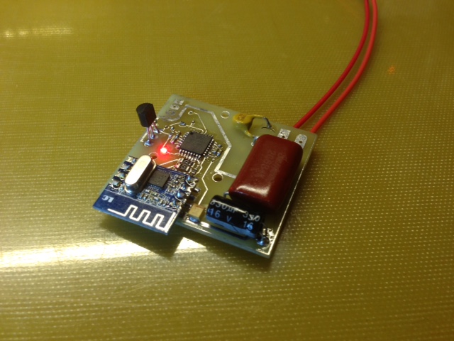
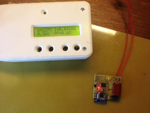
The real consumption measured by RMS wattmeter is just 0.3W
-
Really nice!
I guess the DHT11/22 pin could also be used for PIR sensor or drive a relay/actuator.
-
I've created this to have easiest way to establish environment monitoring across the house
the idea is to have a wall outlet type plug with everything on board
and I like to do small things
The board is less than 50 x 50 mm
It contains AC-DC power supply with resettable fuse, 3.3V LDO, arduino based on atmega328, radio, LED, and two slots, one for DS18B20 and the second one is for DHT11/DHT22The real consumption measured by RMS wattmeter is just 0.3W
-
Really nice!
I guess the DHT11/22 pin could also be used for PIR sensor or drive a relay/actuator.
-
@hek thanks
I read a datasheet and I doubt about where to use it
it requires quite a big external filter
the total size will be bigger than normal isolated AC-DCThe supply based on none-isoleted schema is interested in some projects where you need lower footprint.
If someone interested I will do a test
-
@axillent Very nice! How do you make the circuit board and the soldering of surface mounted components is quit advanced.
@olaeke thanks!
it is half-a-day project including a home-production of the PCB
but it is a 2-year experienceI also use a simplified approach for some PCBs, without drilling, using 0.5mm FR4 cut by office scissors and thermo-transfer technology. This one requires about 30-50 minutes for the production circle.depending on etching speed. For example this two side AC lamp off-timer:
http://radiokot.ru/circuit/digital/automat/81/04.jpg
http://radiokot.ru/circuit/digital/automat/81/05.jpg -
Excellent!
-
@gregl thanks, yes, the same board can be used for any simple 1-2 inputs or 1-2 channel actuator
I have a plan to create something similar for wall switch in 3-wire and 2-wire versions
-
@ServiceXp thanks)
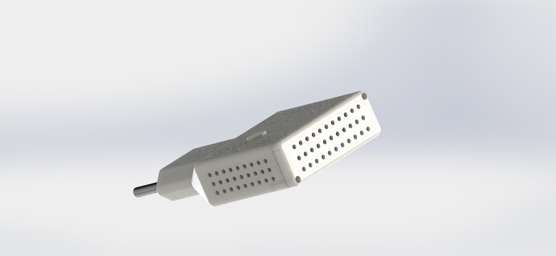
all this is simple, just a patient workPrinted thing is a bit ugly comparing to the virtual one, but it's work is real
http://www.youtube.com/watch?v=JG7gutD1oo8sense and drive
-
@ServiceXp thanks)
all this is simple, just a patient workPrinted thing is a bit ugly comparing to the virtual one, but it's work is real
http://www.youtube.com/watch?v=JG7gutD1oo8 -
@ServiceXp thanks)
all this is simple, just a patient workPrinted thing is a bit ugly comparing to the virtual one, but it's work is real
http://www.youtube.com/watch?v=JG7gutD1oo8@axillent Very impressive! What is the total cost of the components involved?
-
@axillent Very impressive! What is the total cost of the components involved?
@bjornhallberg it is hard to say
the BOM is simple and short
but the cost of a single component is dramatically depends on how many your purchase in a single order
for example atmega328 purchased in 10pcs will be US1.2 pcs while a single pcs will costs US3-4If it will be an interest I think in production this PCB can cost retail US8-12
-
Impressive!
-
made two more with modified box - it is a bit wider to hold DHT sensor inside
I made a new sketch as a combination of Dalas example and DHT. This new sketch able to detect automatically connected sensors and work according to detection.One problem I've got. I cannot get DHT working from AC plug. It is working fine been powered from DC and failed during startup been powered from AC :( The most probably the reason is high pulsation (up to 440mV) coming from the supply based on SR10 chip.
Dalas is fine with this but not DHT. Probably some code inside the library holds.Had to mark each sensor with radio channel because they will work with different gateways
Hello! It looks like you're interested in this conversation, but you don't have an account yet.
Getting fed up of having to scroll through the same posts each visit? When you register for an account, you'll always come back to exactly where you were before, and choose to be notified of new replies (either via email, or push notification). You'll also be able to save bookmarks and upvote posts to show your appreciation to other community members.
With your input, this post could be even better 💗
Register Login