Sensebender Micro


  • That's why I think i'm going to go with this senseboard.
    But I want to be sure that some connectors (D3 ?) support interrupts ? The goal is to have the sensor always in sleep mode, and wake up on interrupts only.

    Regards,


  • @petoulachi D3 can be used for interrupt, just tested it and it works.


  • I vote for one cheap Sensebender version without the temp/hum sensor on it. It will be the perfect door/window sensor.


  • Admin

    @nikos1671

    It has been up before, but back then it was decided that we don't save that much (2-3 $ or something like that). It might also be lower production quantities, which also keeps the price up..


  • @tbowmo just curious do you guys know how many of these you've sold?
    I've bought about 15+ 🙂


  • Admin

    @mvader
    Then you've bought almost 2% of them 🙂

    We're deeply grateful for yours and others support of the MySensors project.


  • Ordered 6 board too ! I'm glad to support MySensors project !


  • I've got 3 coming, can't wait to figure out what I'm going to use them for 🙂


  • @timropp said:

    I've got 3 coming, can't wait to figure out what I'm going to use them for 🙂

    I'm deploying mine all over the house.
    in my attics, garage, shed. bedrooms. etc
    I've attached motion and lux sensors to several of them already.
    I tested / proof of concept adding IR transmitters. but these will likely need to be 5v nano's or something as battery power probably won't work with the IR and staying away waiting for messages from the controller.


  • Got 3 up just using the built in temp/humidity, making sure all looks ok. Will slowly add motion.

    Any suggested motion sensor for these guys?


  • @NotYetRated said:

    Got 3 up just using the built in temp/humidity, making sure all looks ok. Will slowly add motion.

    Any suggested motion sensor for these guys?

    I'm using that HC501 PIR
    you can connect to the side pin and use 3v instead of the 5v


  • Hardware Contributor

    @mvader Can you elaborate how you use 3V on the HC501 ? Which side pin ? Can you post an image ?


  • @GertSanders
    if you look at this image
    on the left side where it says "H" by the 3 pins with the jumper.
    i take off the jumper and connect 3v to the H pin
    works great.
    http://www.bdspeedytek.com/wp-content/uploads/1.1.jpg


  • Hardware Contributor

    @mvader Thanks !


  • Admin

    My Sensebender node started June 10 is still going strong.

    Screen Shot 2015-11-12 at 20.04.18.png


  • Contest Winner

    @hek nice, what tool do you use for logging/graphing? Or is it exported and post-processed?


  • Admin

    @Anticimex

    Datamine for Vera. The actual data is stored to my NAS (mounted from vera).


  • Contest Winner

    @hek cool. Can Vera do that now? Vera lite as well? Though the data miner plugin only could use USB mounts.


  • Admin

    @Anticimex said:

    Can Vera do that now? Vera lite as well? Though the data miner plugin only could use USB mounts.

    Na, a little hack
    http://forum.micasaverde.com/index.php/topic,14910.0.html


  • Hello,
    I've just received my sensebender boards and start playing with it.

    My first goal is to make a door sensor running on battery. I will not use the integrated temp/hum sensor for battery purpose, and use interrupt to have the sensor on sleep the majority of time.

    Looking at the sketch given with temp/hum, I have one question;

    on the loop function, we have

    if ((measureCount == 5) && highfreq) 
      {
        clock_prescale_set(clock_div_8); // Switch to 1Mhz for the reminder of the sketch, save power.
        highfreq = false;
      } 
    

    But I don't really understand this ; highfreq is initialized to true in the declaration, and never again. So, does this clock_prescale_set is call only once, meangin that the sensor will run at 1Mhz all the time ?
    It is the 5 first mesure that are running at normal speed, and then the sensor goes into a "battery efficient" mode ?
    Why waiting for 5 mesure to do so, and not doing it at startup ?

    Thanks for your explanation !


  • Admin

    @petoulachi said:

    But I don't really understand this ; highfreq is initialized to true in the declaration, and never again. So, does this clock_prescale_set is call only once, meangin that the sensor will run at 1Mhz all the time ?
    It is the 5 first mesure that are running at normal speed, and then the sensor goes into a "battery efficient" mode ?
    Why waiting for 5 mesure to do so, and not doing it at startup ?

    Thanks for your explanation !

    It's waiting with switching to lower frequency, because it is dumping debug information to the serial port. And when you switch to 1Mhz, the baudrate is "screwed".

    When that's said, my opinion is that there is not much power to save, with switching to 1Mhz. This is because the MCU is sleeping most of the time, with the RC oscillator switched off. I am thinking that the freq. scaling should be removed in the comming releases


  • Oooh so I guess that also explain why I have strange output on the serial using the default sketch ?

    Well, I'll start without touching frequency and see how it behave in the next month. This is the sketch I use (not tested yet !). Sleeping all the time, awake but interrupt. When awake, send the Battery % if different from last mesure.

    /**
     * The MySensors Arduino library handles the wireless radio link and protocol
     * between your home built sensors/actuators and HA controller of choice.
     * The sensors forms a self healing radio network with optional repeaters. Each
     * repeater and gateway builds a routing tables in EEPROM which keeps track of the
     * network topology allowing messages to be routed to nodes.
     *
     * Created by Henrik Ekblad <henrik.ekblad@mysensors.org>
     * Copyright (C) 2013-2015 Sensnology AB
     * Full contributor list: https://github.com/mysensors/Arduino/graphs/contributors
     *
     * Documentation: http://www.mysensors.org
     * Support Forum: http://forum.mysensors.org
     *
     * This program is free software; you can redistribute it and/or
     * modify it under the terms of the GNU General Public License
     * version 2 as published by the Free Software Foundation.
     *
     *******************************
     *
     * REVISION HISTORY
     * Version 1.0 - Henrik Ekblad
     * 
     * DESCRIPTION
     * Default sensor sketch for Sensebender Micro module
     * Act as a temperature / humidity sensor by default.
     *
     * If A0 is held low while powering on, it will enter testmode, which verifies all on-board peripherals
     *  
     * Battery voltage is as battery percentage (Internal message), and optionally as a sensor value (See defines below)
     *
     */
    
    
    #include <MySensor.h>
    #include <Wire.h>
    #include <SPI.h>
    #include "utility/SPIFlash.h"
    #include <EEPROM.h>  
    #include <avr/power.h>
    
    
    #define RELEASE "1.0"
    
    // Child sensor ID's
    
    #define DIGITAL_INPUT_SENSOR 3   // The digital input you attached your motion sensor.  (Only 2 and 3 generates interrupt!)
    #define INTERRUPT DIGITAL_INPUT_SENSOR-2 // Usually the interrupt = pin -2 (on uno/nano anyway)
    #define CHILD_ID_DOOR 1   // Id of the sensor child
    
    
    MySensor gw;
    
    // Sensor messages
    MyMessage msgDoor(CHILD_ID_DOOR, V_TRIPPED);
    
    // Global settings
    int measureCount = 0;
    int sendBattery = 0;
    boolean highfreq = true;
    
    // Storage of old measurements
    long lastBattery = -100;
    boolean oldDoorValue;
    
    /****************************************************
     *
     * Setup code 
     *
     ****************************************************/
    void setup() {
      Serial.begin(115200);
      Serial.print(F("Sensebender Micro FW "));
      Serial.print(RELEASE);
      Serial.flush();
      
      gw.begin();
    
      Serial.flush();
      Serial.println(F(" - Online!"));
      gw.sendSketchInfo("Battery Door", RELEASE);
    
      // sets the motion sensor digital pin as input
      pinMode(DIGITAL_INPUT_SENSOR, INPUT);     
      // Activate internal pull-ups
      digitalWrite(DIGITAL_INPUT_SENSOR, HIGH);
      
       // Register all sensors to gw (they will be created as child devices)
      gw.present(CHILD_ID_DOOR, S_DOOR);
    }
    
    
    /***********************************************
     *
     *  Main loop function
     *
     ***********************************************/
    void loop() {
      gw.process();
    
      sendBattLevel(false); 
      door(false);
      
      gw.sleep(INTERRUPT, CHANGE, 0);
    }
    
    //  Check if digital input has changed and send in new value
    void door(bool force) 
    {
      // Short delay to allow buttons to properly settle
      sensor_node.sleep(5);
      
      bool tx = force;
      
      boolean tripped = digitalRead(DIGITAL_INPUT_SENSOR) == HIGH; 
      
      if (tripped != oldDoorValue) 
      {
        tx = true;
        oldDoorValue = tripped;
      }
      if (tx)
      {
         // Send in the new value
         gw.send(msgDoor.set(tripped ?  1 : 0));  // Send tripped value to gw 
      }
    } 


    /********************************************
     *
     * Sends battery information (battery percentage)
     *
     * Parameters
     * - force : Forces transmission of a value
     *
     *******************************************/
    void sendBattLevel(bool force)
    {
      if (force) lastBattery = -1;
      
      long vcc = readVcc();
      
      if (vcc != lastBattery) 
      {
        lastBattery = vcc;
    
        // Calculate percentage
        vcc = vcc - 1900; // subtract 1.9V from vcc, as this is the lowest voltage we will operate at
        long percent = vcc / 14.0;
        gw.sendBatteryLevel(percent);
      }
    }
    
    /*******************************************
     *
     * Internal battery ADC measuring 
     *
     *******************************************/
    long readVcc() {
      // Read 1.1V reference against AVcc
      // set the reference to Vcc and the measurement to the internal 1.1V reference
      #if defined(__AVR_ATmega32U4__) || defined(__AVR_ATmega1280__) || defined(__AVR_ATmega2560__)
        ADMUX = _BV(REFS0) | _BV(MUX4) | _BV(MUX3) | _BV(MUX2) | _BV(MUX1);
      #elif defined (__AVR_ATtiny24__) || defined(__AVR_ATtiny44__) || defined(__AVR_ATtiny84__)
        ADMUX = _BV(MUX5) | _BV(MUX0);
      #elif defined (__AVR_ATtiny25__) || defined(__AVR_ATtiny45__) || defined(__AVR_ATtiny85__)
        ADcdMUX = _BV(MUX3) | _BV(MUX2);
      #else
        ADMUX = _BV(REFS0) | _BV(MUX3) | _BV(MUX2) | _BV(MUX1);
      #endif  
     
      delay(2); // Wait for Vref to settle
      ADCSRA |= _BV(ADSC); // Start conversion
      while (bit_is_set(ADCSRA,ADSC)); // measuring
     
      uint8_t low  = ADCL; // must read ADCL first - it then locks ADCH  
      uint8_t high = ADCH; // unlocks both
     
      long result = (high<<8) | low;
     
      result = 1125300L / result; // Calculate Vcc (in mV); 1125300 = 1.1*1023*1000
      return result; // Vcc in millivolts
    }


    BTW, what is the F() function ? instead of Serial.print("Sensebender Micro FW "); why using Serial.print(F("Sensebender Micro FW ")); ?

    Thanks !


  • Started to solder my 6 sensebender. I've noticed that if I set it to 1Mhz directly, the sensor cannot register itself on the gateway (but unfortunately I dont know why because there's no serial). Putting it at 8Mhz, being detected by the GW with an ID, and I can set it back to 1mhz. Weird.


  • Oh and BTW, which boxes are you using with your Sensebender ? I guess it's maybe the most difficult part of the entire project, finding the perfect box 😄


  • No, finding a box is the easiest part. This is the "box" for my outdoor temperature. 😆
    sensebender.jpg


  • Admin

    Wonder how well the hum-sensors work in that enclosure 🙂


  • Hmm, would Gore-Tex work? I will try find a Gore-Tex bag for the next version 🙂


  • @Fabien said:

    @5546dug said:

    @fabian how is the box working out were there any mods and are the stl files ready yet?

    Sorry, my 3D printer is out of service, I'm waiting for chinese parts ... I will post correct STL files in 1 or 2 weeks.

    @Fabien @5546dug
    Hi, any news on this please? I would be good to get a box by Christmas.


  • Admin

    @petoulachi

    The sketch have improved a lot since we released the sensebender, mostly on determining when to power up the radio and transmit. This should save more power. I've got one running with latest development, without hiccups for the last couple of months (it also have Ota fw upgrade enabled by default now).

    So if you are "adventurous" I would recommend to put that into your sensebenders


  • I am adventurous !

    Were can I find the beta version of the sketch ?


  • Hero Member


  • Thanks !

    I took a look at the sketch, I didn't know there was a presentation() method to implement to present the different sensor's ID; is this new ? when is it called? I guess after setup() ?


  • Admin

    @petoulachi

    That's a part of the development. Things are re-arranged in the sketches, to make things more configurable (from within the sketch itself).

    It will be part of the next release (I don't know when that is happening)


  • Ok, related to MySensors 1.6 tehen, that explain why I never seen this !


  • HI, I'm about to experiment with a modded version of the sensebender and I while looking at the schematics of the original sensebender, I see that the crystal does not have any pf capasitors and not connected to GND. Why is that?

    All other schematics of atmega or any microprocessor I've seen has dual 22pf caps over the crystal and connected to ground.


  • Admin

    @Magnus-Pernemark

    The sensebender was designed to use a 32Khz oscillator for lowpower operation. According to the datasheet (page 33) it is not necessary to have external load capacitors if the crystals datasheet specifies cL below 6pF.

    However, we decided early on that an external crystal is not necessary in our application. So that is why it is not mounted, but the pads are still there, in case someone would use it.


  • @tbowmo Thanks! Yes. I read that it was not needed, but since it said "if you want higher precision" I though that, higher is good, and it would not hurt to place one there. But the crystals I have are 12.5pf so I guess I can't use them, but on the other hand I don't need to buy any other


  • Did someone "test" the humidity precision of the Si7021on the sensbender? Of corse the datasheet says max 3% off but how reliable is that?

    I have other sensors here and they differ by about 10%. So I did a "Salt-Calibration-Test" and there my two sensbenders or better Si7021 are 6% over the reference value. They report 81% and it should be 75%.

    Note: It's my first time that I performed this test and I'm not 100% sure that the (water-salt-ratio) is correct - thats why I'm interested if someone else tested the values?


  • Admin

    @nivoc

    Salt and electronics isn't a good combination, it will cause corrosion of the copper tracks..

    Just to warn you a little bit 🙂


  • @tbowmo Thanks. No worries the electronic won't touch the salt or water. The salt/water is just within the same closed container to bring the enclosed air to exactly 75.3% rel hum (at 25C).

    I followed this howto: But there are many other similar ones.
    http://www.kingofthehouse.com/hygrometer/


  • @nivoc I setup several sensebenders on battery last summer and noticed they were a few % below two dht22 I had been running for months. I did the saturated salt test on three sensebenders with one dht22 and one mechanical hygrometer and the sensebenders all read 74-75% while the DHT and hygrometer read 78-80%. Not a perfect test and i dont know which devices were correct but one thing I noticed was the sensebenders consistently provided the same result across different devices. Relative humidity is relative.


  • @Dwalt
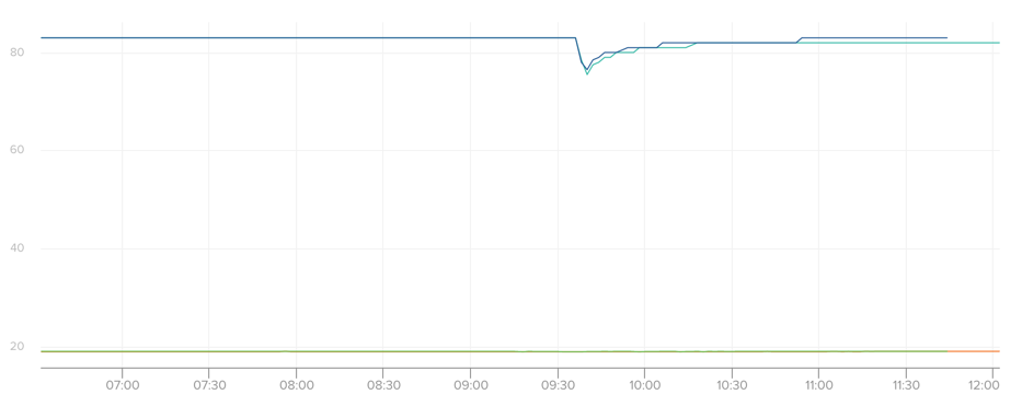
    Thanks for the info. I'm currently opening the box every several hours to test the salt soup. My room has something between 50 and 60 rel. (so below 75). And every time I open the box this (see pic). It drops and goes back up to 82 or 83. Than it stabilizes there over the next couple hours. There are two sensbenders in the box - thats what the two line are. And yes they are remarkable equal. But it always goes to 82 - i would hope for 75. But I will repeat this procedure until it starts to stabilizes after every opening a little bit below the value that was there before the opening. Because if that happens i am below the dry point and than I will test in a room with humidity higher than 80 and test if soup can do the same into the other direction and holds it stable for many openings. THAN i know that the salt is performing is job correctly and know that the test is good and the senbender is wrong 🙂 or hopefully I learn the opposite.

    upload-555b12a4-6bc0-4e07-acf7-976c4122e6d6


  • Yes it looks like that the sensors are 8% off. I tested the other way around >opening at ~100rel and closing and same + exactly back to 82/83 and it should be 75% :-).

    upload-e6c04b83-54d0-4e1e-aef3-a36b72c760d5


  • In the new year I will test with "Magnesium chloride". It brings the rel humitity to exactly 32% - I will report how that goes 🙂


  • Admin

    If the Si7021 is exposed to high humidity for a prolonged period, the RH% measurement will shift upwards, according to the datasheet, page 15, section 4.3

    Extract from Datasheet:

    4.3. Prolonged Exposure to High Humidity
    Prolonged exposure to high humidity will result in a gradual upward drift of the RH reading. The shift in sensor
    reading resulting from this drift will generally disappear slowly under normal ambient conditions. The amount of
    shift is proportional to the magnitude of relative humidity and the length of exposure. In the case of lengthy
    exposure to high humidity, some of the resulting shift may persist indefinitely under typical conditions. It is generally
    possible to substantially reverse this affect by baking the device (see Section “4.6. Bake/Hydrate Procedure” ).


  • Hero Member

    @petoulachi said:

    BTW, what is the F() function ? instead of Serial.print("Sensebender Micro FW "); why using Serial.print(F("Sensebender Micro FW ")); ?

    It's a way to save some RAM. A simple string constant like "Hello" takes up 6 bytes of RAM and also 6 bytes of Flash (program) memory (6 bytes includes a single "hidden" byte of binary zero as an end-of-text marker). At startup and before your code executes, that bit of program memory is copied to RAM. The F() thing is a "macro" which causes the compiler save only the 6 bytes of Flash (no Ram used). The print function can (through C++ typing) fetch those 6 bytes from Flash at runtime for printing. If you have long or many text constants in your program, this can add up to some useful savings,when you only have 2K of RAM.

    See the "F() Macro" on this page: https://www.arduino.cc/en/Reference/PROGMEM


  • @tbowmo Good hint. But it is happening to all three sensbeners for at least one month now. (different orders). I now got 4 more so I will test again soon.

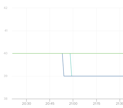
    Over xmas I tested also with magnesium chloride hexahydrate. magnesium chloride hexahydrate produces exactly 33%rel.

    All 3 sensbenders report exactly 39% or 40%. So they are also here 7% off. But almost the same value and very reproducible - so thats great!

    upload-6b1782fc-cf3e-45b8-ad15-890b7eef84a0


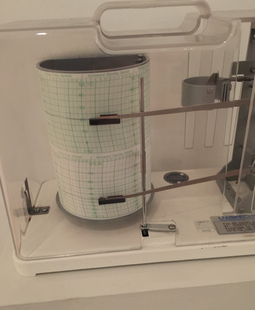
  • @tbowmo I'm now almost sure that my test-setup has no faults very reproducable and read many articles - I plan to verify my findings with someone who has a professional calibrated device.

    I saw in a museum nearby that they have professional calibrated devices 🙂
    upload-4464b273-5525-48b2-a940-10826e61f030

    So I will test against those 🙂


  • Admin

    @nivoc

    Have you tried to "bake" your sensebenders, in case they have been exposed to high humidity for a longer time?

    They are, as far as I know, produced in a part of China, which are known to have very high humidity. (been traveling there a lot some years ago)


  • Hero Member

    @nivoc
    I can confirm your results: I am running two different sensors in the same room next to each other. The sensebender is always above the dht-22. Right now it is
    52% to 47.8% rel. humidity, while the temperature is 17.8 to 17.9 (which is nearly equal).


  • @tbowmo No I haven't baked yet. I will try that but not in the next two weeks. But I will report back.


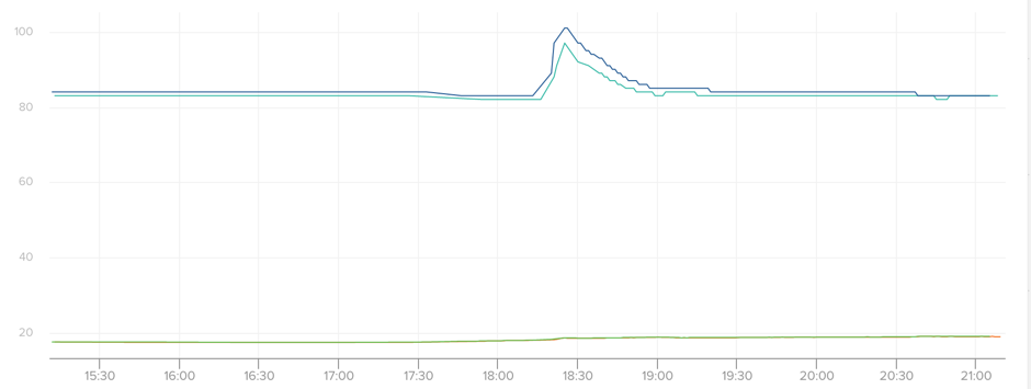
  • But I tested tonight with distilled water - so should be exactly 100%. And again (I didn't know that thats possible) I got 104 and 107% so slightly above (still increasing). Thats great b/c that means all values are about 7-8% too high.
    At 33% the reading was about 40%
    At 75% the reading was about 83%
    At 100% the reading was about 106%

    So reading minus 8% gives a pretty accurate result. In the next few days i will test 3 more sensbender.

    Distilled Water (100% expected):
    upload-c0364fcd-876d-4701-a3ec-b0c55efc04a6


  • Read the spec for the humidity sensor used in the sensebender (Si7021 integrated humidity / temperature sensor.)
    Precision Relative Humidity Sensor: ± 3% RH (max), 0–80% RH
    To my reading this is actually 6% wrong reading to one of the sides - so when you are measuring yours to be 8% off, is caused that you are using the device outside of humidity range 100% and max is 80%

    Link to spec:
    https://www.silabs.com/Support Documents/TechnicalDocs/Si7021-A20.pdf

    What I want you to know, if your device is reading within 6 % of the value - it's still reading correct. and when you compare ex DHT22 that device also have some reading variation error. Do not expect to get 100% perfect value for 2 devices...


  • @bjacobse Yes and no 🙂

    Yes 100% is outside of the spec.

    And no. 33% with Magnesium Chloride Hexahydrate is inside the spec and I get 40% instead of 33-34%.

    Max off should be 3% above or? Means 37% - but fair enough. Should be ok for household use.


  • @nivoc said:

    @bjacobse Yes and no 🙂

    Yes 100% is outside of the spec.

    And no. 33% with Magnesium Chloride Hexahydrate is inside the spec and I get 40% instead of 33-34%.

    Max off should be 3% above or? Means 37% - but fair enough. Should be ok for household use.

    I hope the Temp measurements are not off by that much.
    i don't need .00001 accuracy or anything. but i feel a big difference between 70 and 72 in my house.


  • @mvader
    Spec is: High Accuracy Temperature Sensor ±0.4 °C (max), –10 to 85 °C
    So the temp accuracy is quite good


  • @nivoc
    Yes you are right, +-3 from your humidity solution on 33%, then the reading could be in the interval 33-3=30% or up to 33+3=36% and should not show 40%

    did you get same false readings from other sensebender humidity sensors?


  • @bjacobse Yes I have 3 sensbener running from 2 different orders. All 3 are very near by each other. So at 33% they all read something near to 40%.

    I have 4 more sensbenders to build. However I continue to test tonight with a Boveda-Pack that claims to bring the hum in a containter to exactly 69%. I did 4 test's so far and also used different technics. So i get more and more confident.

    But the very good thing is - it looks every reproducible. So the value may be off but reproducable accurate off by about 8%. When I completed my test it will be very easy to correct it within the software.


  • @mvader I haven't made any very accurate temp testings. But the readings are exactly the same than other non-sensbender devices in my home. I started researching the humidity b/c I had different readings between different devices.

    Temp looks fine to me.


  • What is the current consumption of the Sensebender during sleep and active modes?

    Thanks,
    Tony


  • Admin

    @tcontrada

    there are some measurements in the old design thread here http://forum.mysensors.org/topic/510/minimal-design-thoughts


  • Hi. What case you all using for the sensebender ?Any good idea.


  • 3_1456326631089_IMG_20160224_150344.jpg 2_1456326631089_IMG_20160224_150314.jpg 1_1456326631089_IMG_20160224_150303.jpg 0_1456326631088_IMG_20160224_150237.jpg


  • Admin

    @filipq

    Where did you find that box?


  • @tbowmo

    Got it from http://cpc.farnell.com/1/1/57932-evatron-pp42m-case-sensor-ivory-71x71x27mm.html.
    Not the cheapest, but definitely worth the money as it is very good quality. There are other colours available (white and black) https://www.jprelec.co.uk/store.asp/c=552/Gas-Sensor-Case


  • Hardware Contributor

    @tbowmo: I have some of these too, it's nice box. i got these from tme. cheaper 🙂
    http://www.tme.eu/fr/details/box-sens-white/boitiers-dappar-dalarme-et-de-capt/supertronic/


  • Hello @tbowmo

    Doesn't the atmega328 has only 2 pins which are D2 and D3 from external interrupts ?
    I am wondering why do we waste the usage of D2 since the IRQ pin is not used in the library ?


  • Contest Winner

    @ahmedadelhosni because it is not in use by the library <yet>. Would be a shame if the library some day gets updated with support for a radio that can enter low power sleep and still wake when needed.


  • Admin

    @ahmedadelhosni

    What @Anticimex said.. And at the time when I created the sensebender, I didn't know that the interrupt wasn't used (I was relatively new to the project) so I thought that we had to have it connected..


  • Admin

    It is used by the RF69, right @tbowmo? (when using adapter plate...)


  • @Anticimex @tbowmo This a valid point which I thought of but I needed two interrupt pins. As far as I knew from fast searching is that external interrupts which react to CHANGE in pin state are only valid for pins 2 and 3. Correct ?
    Maybe there is another solution which I missed.


  • Admin

    @hek

    Yes, that's right, RFM69 is using interrupts.. (and rfm69 is possible on the sensebender using for example this pcb)


  • Contest Winner

    And with a scalpel and a soldering iron you should be able to use both interrupts by disconnecting the one reserved for nrf24. Of course that would disable the use for rfm69 om that board.


  • @Anticimex Yeah I could just connect my device to the atmega pin directly as I can see/find any pin header to route the interrupt pin 2. They are all used.

    Thanks guys.


  • Contest Winner

    I just received two sensebenders. I'm really impressed by the great engineering behind the board. I can't wait to heat up my soldering iron. I love them!


  • I just received two Sensebenders, but have problems getting the device to consume little power. I get totally different values as displayed above.

    With the following sketch, I get about 5,6mA in active state and 1,6mA in sleep mode with nRF24 attached. I have compared different nRF24-chips and this one consumed the least power.

    Without the nRF24, I get 4mA and 0,025mA (=25µA) during sleep mode.

    #include <LowPower.h>
    #include "RF24.h"
    
    RF24 radio(9, 10);
    
    void setup() {
    }
    
    void loop() {
        delay(8000);
        LowPower.powerDown(SLEEP_8S, ADC_OFF, BOD_OFF);
    }
    

  • Mod

    @user2334 I don't think the LowPower library shuts off the radio. Use MySensor's sleep function instead.


  • A general question regarding these types of boards that are generally designed to be used on battery power. Is there a reason to not power the ATSH204A and Si7021 from AVR pins? The pins can source far more than what these devices can sink (even when using the heating on the Si7021), and it would allow squeezing a tiny bit more out of the battery life by selectively powering down the devices.
    Eg., if I'm not using the ATSHA204A at all, I can save 150nA continuous current. The power saving from disabling the Si7021 is less at about 60nA, so that might just be eaten up by having to wait up to 80ms before a full conversion.

    I'm aware that we're talking about saving a tiny ~200nA here, but over the span of two years that adds up to about 350mAh.

    So what I'm wondering is simply, is there a technical reason saying that this really isn't a Good Idea (tm)? Should I avoid doing so if I design my own similar device?


  • Hardware Contributor

    @ximinez said:

    A general question regarding these types of boards that are generally designed to be used on battery power. Is there a reason to not power the ATSH204A and Si7021 from AVR pins? The pins can source far more than what these devices can sink (even when using the heating on the Si7021), and it would allow squeezing a tiny bit more out of the battery life by selectively powering down the devices.
    Eg., if I'm not using the ATSHA204A at all, I can save 150nA continuous current. The power saving from disabling the Si7021 is less at about 60nA, so that might just be eaten up by having to wait up to 80ms before a full conversion.

    I'm aware that we're talking about saving a tiny ~200nA here, but over the span of two years that adds up to about 350mAh.

    So what I'm wondering is simply, is there a technical reason saying that this really isn't a Good Idea (tm)? Should I avoid doing so if I design my own similar device?

    I second that question. I was just thinking about a similar idea.


  • Admin

    @ximinez @LastSamurai

    That is indeed a good question. The straight answer is that I didn't think about that when I designed the board.

    In theory you could also power the radio from a digital pin on the avr, and power that down completely.

    BTW. If you turn on the heating element in the si7021 at full power, I think the power drain exceeds what the avr can deliver on a digital pin. But one could just avoid that.


  • Contest Winner

    I have been thinking about this as well. But I discarded parts of the idea because I needed the IO for other stuff (MYSX in my case). Instead I designed a switched rail where one could attach sensor power sinks. It's not io powered but it is io controlled.
    Though I did not attach the si or atsha to this switch function as I decided to make it an optional feature but wanted to make sure authentication and temp/hum would always be available.


  • That is indeed a good question. The straight answer is that I didn't think about that when I designed the board.

    Oh, I thought it was a design decision 🙂

    In theory you could also power the radio from a digital pin on the avr, and power that down completely.

    I've been wondering about the radio in particular. Does the radio keep any state locally, and will it have to be reinitialized upon powerup?

    BTW. If you turn on the heating element in the si7021 at full power, I think the power drain exceeds what the avr can deliver on a digital pin. But one could just avoid that.

    The heating element eats a measly 3.1mA according to the datasheet, so even that would be well within the limits for a single in on a 328p.

    Now, I don't have Eagle installed on this laptop, and my bandwidth is limited right now. Is there a picture of the PCB traces available? Wondering if atleast some of this can be hacked on by cutting traces.


  • Admin

    @ximinez

    Nope, there are only the eagle design files.. (Or gerbers, you could use a gerber viewer)

    I have 4 sensors operating for almost a year on two AA batteries, they all report around 73% battery left. So in my opinion, it's not that necessary to do extra optimization on the power drain..


  • @tbowmo
    While 73% after one year is good, it doesn't mean that it can't get better. The ATSHA204a and Si7021 draw about 350mAh from the battery over two years from idling alone. The NRF24L01+ draws around 1500mAh.
    Remember, you will never get close to emptying out the battery before the voltage drops below working voltage. Using alkaline batteries, you'll get around 2000mAh before the batteries reach 2v (which, if you're using battery voltage as a pure percentage, is 66%), at which point the voltage curve drops sharply - and your sensors die. The radio and sensors have drawn more than 900mAh from your battery during the year you have run the device (and that's just idling) - close to half your battery life.

    Assuming your battery percentage is correct, and you started at 100% one year ago, I'm betting your sensors will die sometime during this summer. While you may think that extra optimization isn't worth it, I do. The nanoAmp draws may not seem like much, but drawn out on a timescale like this, it is a major power draw.


  • Contest Winner

    @ximinez That depend on how you define battery percentage. I have chosen to adjust my measurements to let 0% mean when voltage drops below the highest requirements of the onboard devices. Since that particular device will fail when voltage goes lower, it serves no purpose to provide a false battery percentage. 0% is when the node no longer operates according to specs. But this is of course hw/sketch-dependent.


  • @Anticimex The point still stands however. The discharge graph is far from linear, and your sensors and radio have already drawn close to half of your battery life by idling alone. A colleague of mine has had to replace the batteries in his two sensors already.


  • Contest Winner

    @ximinez I do not recall sharing my statistics, so I assume you refer to @tbowmo's stats?


  • @Anticimex Ah, yes. sed /your/@tbowmo's/g. I blame lack of caffeine.


  • Contest Winner

    @ximinez makes sense. I'm sure you can cut down on power consumption by cutting power to those peripherals. I do not know how signing would be affected by this though, as I have not tested it with switching the atsha on and off between calls. I would like to hear from you on that topic if you choose to try it though 🙂


  • Ok, I've been looking at the image and my spare sensor. It looks like:
    Power to the NRF can be cut between C3 and VCC pin.
    ATSHA204a power can be cut on the trace that goes from the atsha and beneath the flash.
    Si7021 power can be cut at the trace that goes from C4.

    I just might have to dig out my scalpel and iron for this. If the components magically work without any extra initialization on powerup, modifying the code looks easy.

    I'll report back with my findings


  • Admin

    @ximinez

    For my battery reporting, I have set 1.9V as 0%, 3.3V is 100%..

    While you're at it, also power down the external flash, as it might also contribute a bit..


  • Well that went south pretty fast. Was wondering why my sensebender was acting up. Took a while to see that I had plugged in an ESP8266 module instead of one of my NRF24 modules. Those modules look far too much alike 😡

    Serial output now looks like this: "Sånsebåndåò Micro FW 1.3" with random characters corrupted. I think I've killed it 😉
    I can still flash firmware to it via serial, so it's not completely dead.

    I can however confirm that both the SHA204A and SI7021 self-tests OK being powered on in-sketch:
    (Flash seems to randomly fail or test OK, not sure why yet)

    þSånseâånder Micòo F× 1.3 - TesôÍoäe
    Tåstiîg påòipheraló!
    -> ÓÉ7021 : ok!
    -> Æìasè : æailed!
    -> SÈA204 : Ïk (seòéal : 01234ÂBAÅ259E8AÄÅE)
    Tåót fiîésheä
    ----> Óelftest æaiìåä!


  • Contest Winner

    @ximinez If possible, try to check if signing and verification of signatures work as well. I have tried to implement the use of the ATSHA to be atomic in nature, but it could be that some state is retained which is cleared on power down which might break the calculations.


  • What is the easiest and fastest way to sign and verify? I don't have a gateway set up quite yet.
    (And, is any part of setting this up dependent on serial integrity? If so I might have to adjust baud quite a bit)


  • Contest Winner

    @ximinez Well, without a gw the only option is to use node peer to peer transmissons to test signing. How to do it is described in the signing documentation, assuming you use development branch, you can see here. For master, look here.


  • I have an Uno with an ethernet shield and nrf24 hooked up, so I will have to get around to write a sketch for that purpose.
    But to get signing to work, I'll have to personalize the atsha? That sketch doesn't compile for me.


  • Contest Winner

    Yes, you have to personalize it. What is failing? I don't have an Uno myself, but according to Jenkins the personalizer compiles ok for Uno on both master and development. You don't have any local changes?


  • The personalization fails to compile for my sensebender micro. There's a few undeclared:

    Personalizer:225: error: 'EEPROM_SIGNING_SOFT_HMAC_KEY_ADDRESS' was not declared in this scope
    Personalizer:225: error: 'hwReadConfigBlock' was not declared in this scope
    Personalizer:236: error: 'EEPROM_SIGNING_SOFT_SERIAL_ADDRESS' was not declared in this scope
    Personalizer:247: error: 'EEPROM_RF_ENCRYPTION_AES_KEY_ADDRESS' was not declared in this scope
    Personalizer:697: error: 'hwMillis' was not declared in this scope

    I'm trying to compile this against master however. Do I have to have dev branch to compile that sketch?


  • Fails with the same errors on Uno for me.


  • Contest Winner

    @ximinez and you are certain you have no local changes to the code? Jenkins builds both master and development branches every night for both the SenseBender and the uno and it builds all examples, including the personalizer without issues.


Log in to reply
 

Suggested Topics

  • 3
  • 109
  • 10
  • 347
  • 163
  • 5

24
Online

11.2k
Users

11.1k
Topics

112.5k
Posts