NRF24L01+ range of only few meters


  • Hey there,

    I have multiple NRFs bought on ebay. Those are probably not genuine, but up to now they worked. I was only building sensors on my desk and tested them. Now I wanted to move one of my sensors... and got no receiption. Moving it back to my ESP gateway I got it back working at a range of about 4-5 m with only a lite wall in between. I think thats not the normal range, or many others would have realy a problem.
    Is this maybe caused by bad ESP positioning (short cable on my pc for new uploads, next to some mains adaptors and my monitor)? Or might it be caused by many wifi-networks in our area?
    Does anyone have a good idea how to get better range?


  • @sundberg84 I have the same problem. Can't get those radios talking to each other over a distance longer than 3 meters. I did everything described in many other posts. Capacitors, seperate 3.3v power source, etc, etc.

    Only thing is, gateway is Uno powered from the USB port on my computer and sensor is Pro Mini powered through a phone charger. I supply 3.3V regulated power through LM1117 on the sensor. However, I use Uno's 3.3V on the gateway. I am using MYSController to test the connection.

    I am really enthusiastic about MySensors project, but really got stuck at this very first stage. Please, need help.


  • the 3.3V on the arduino boards suck. Do not use that, instead use the 5V with your own 3.3V regulator.


  • Hardware Contributor

    Well, you should be able to debug by changing position of the sensor and see if that helps. If you have a 3.3 try to power it with 2xAA (little noice) to see if that helps. Also if you move the sensor it might need some time to find its way through the network if you have repeaters and so...


  • @ericvdb said:

    the 3.3V on the arduino boards suck. Do not use that, instead use the 5V with your own 3.3V regulator.

    I'm using 7 nodes with nRF directly connected to my 3.3v pro mini's vcc. Never had any problems with range, since I'm using the nRF Version with antenna on my gateway.

    @Anduril are you using capacitors? Try exchanging the nRF which is attached to your gateway.


  • I also have such problems, the following video helps me. I use 3.3V pro mini.
    Cheap DIY NRF24L01 Antenna Modification – 02:48
    — Pete B


  • Mod

    @sven said:

    the following video helps me

    @petewill strikes again 😉


  • Hero Member

    I have an issue in a room where nothing goes out (but before yes...) : nor Zwave or nrf24L01 from itead in normal or amplified, either on batteries or on AC... any idea how to investigate this ?

    Some wifi is in, I am wondering of a local gateway to wifi to circumvent this...


  • Hero Member

    @sven is this a quartew or half wave what he proposes ?


  • @epierre
    petewill propose full wave antenna, please look here: http://forum.mysensors.org/topic/775/8-lamp-outlet-smart-plug-module/67


  • Hero Member

    @sven I did ad a home made half wave on a 433Mhz device (Imagitronix), and also added a quater wave on the RFXTRX to improve the range.

    Frequency = 868 MHz
    Quarter Wavelength: 82.2 mm = 3.235 inch
    Half Wavelength: 164.3 mm = 6.470 inch

    so it is a quarter Wave as the amplified version propose


  • @epierre
    The NRF24L01+ is working on an other frequency, it is 2400 MHz and not 868 MHz. I think to post http://forum.mysensors.org/topic/775/8-lamp-outlet-smart-plug-module/67 might be correct.


  • Hero Member

    @sven on the video he shows 83.38 ?? you are right, it is 2.4GHz

    1/4 wave antenna is 31.25 mm long
    1/2 wavelength is 62.5mm.

    so why did he mesured 83.38 ? was it inches ? (imperial non universal?)


  • @HenryWhite yeah I have caps at all my nrfs. Will try with a different power source, as mine is attached to my pc usb as well. At least for testing it should work on batteries.


  • Mod

    @epierre said:

    @sven on the video he shows 83.38 ?? you are right, it is 2.4GHz

    1/4 wave antenna is 31.25 mm long
    1/2 wavelength is 62.5mm.

    so why did he mesured 83.38 ? was it inches ? (imperial non universal?)

    As Pete explains in the video, you need to add 83.38mm to the pcb antenna to get a full wavelength.


  • Hero Member

    @mfalkvidd said:

    83.38mm to the

    I'd like to understand @petewill


  • @Anduril said:

    @HenryWhite yeah I have caps at all my nrfs. Will try with a different power source, as mine is attached to my pc usb as well. At least for testing it should work on batteries.

    If that doesn't help try exchanging the Gateway Radio module.


  • Basically, from what I understand, a few meters of range is abnormal, and there is something I am doing wrong (a lot of which you outlined above and elsewhere). I understand that if powered correctly and fitted with capacitors and, if need be, some home made antennas, they should communicate through concrete walls up to 10-20 meters.

    Do you confirm? Only then I will have the stamina to go back and spend another weekend crouched on that desk. 😉


  • Mod

    The nrf should have about the same range as regular wifi. So if regular wifi works in that room, you should be able to get the nrf working. If wifi doesn't work, you are not likely to get the nrf working either. In that case you'll probably be better off using ethernet (place an ethernet gateway in that room, with wired access to your home network) or use rs485.

    10-20m solid concrete is going to be tough (for almost any type of radio signal), but with regular walls you should get at least 10m, probably 20-50.


  • Admin

    @epierre my notes are in inches so forgive me not converting it here. My thinking was to make a full wavelength antenna using the existing pcb antenna. A full wavelength antenna for 2.4GHz is 4.92 in. I measured the existing pcb antenna on the nRF and it was 1.64 in. So, 4.92 - 1.64 = 3.28 in. (or 8.3312 cm). I'm not claiming to be an expert at all (an other people have said this shouldn't work) but it has worked well for me so I keep doing it. 🙂 Others have reported success too so hopefully it will help you.

    (thanks for your help @mfalkvidd)

    @nunver Have you changed the PA level to MAX in myconfig.h?


  • Have you tried changing #define RF24_DATARATE in MyConfig.h from RF24_250KBPS to RF24_1MBPS or RF24_2MBPS?

    That helped in my case. But you have to recompile gateway and node(s).


  • @HenryWhite I tried with my ESP on battery and only get few meters range, too.
    Also changing radio did not change anything. But my radios are from the same seller, even if my second batch was ordered months after the first. So maybe still same typ of radios.
    I will check for @VooDooX hint and change datarates. I will report back...


  • Hero Member

    @petewill when you solder you are at the end of the existing antenna, so you should add both length right ? and yes using imperial unit is well... non international 😉


  • Admin

    @epierre Yep, 1.64 + 3.28 = 4.92in is that what you're referring to?


  • I also have a poor range. With all the tricks:

    • pairs of electrolytic+ceramic capacitors

    • short leads

    • max out emittance power

    • lowered KBS to 250

    • increased retries and delays

    • free of wifi interference freq

    • lowered payload to 4 bytes

    • powered usb hub for gateway

    • laptop USB powered arduino for sensor

    • what I did not try - is separate step down regulator for radio

    I got 10m at most through couple of walls. These are plain wood frame + drywall + insulation walls.
    Even that was only possible with max power output on both sides and 250KB/s speed + 4bytes payload. I'm not sure if mysensor serial protocol allow to change payload size. I had to go down to roots of nrf24 programming to debug my poor reception.
    Payload size was the greatest impactor by the way I had to make my own test hardware+software to do these range tests (simple echo server, sending time back, thus 4 bytes payload)

    I've almost give up on nrf24 and ordered 4 hopeRF 483MHz transceivers for testing.


  • Mod

    @Igor-Katkov did you get better results with higher output power? I am no radio expert, but most stuff I have read says that higher output often results in worse signal to noise ratio.


  • @mfalkvidd Yes, a few more meters with PA_MAX.
    Here is my best performing code

      radio.setPALevel(RF24_PA_MAX);
      radio.setDataRate(RF24_250KBPS);
      radio.setPayloadSize(4);
      radio.setChannel(2);
      radio.setRetries(15, 15);
    

    Full code https://gist.github.com/ikatkov/6df540838bd4d3ea8b57


  • Mod

    @Igor-Katkov interesting. Thanks for sharing!


  • It appears that I was quite foolish expecting FTDI adapter board to power my nrf24 😞
    datasheet says it can provide at most 50mA.

    I'll try 2AA batteries and a step up regulator


  • @petewill Yes, I did increase PA level to Max. I don't understand how I could change the payload size, though. Mysensors have a certain format.


  • Hero Member

    @Igor-Katkov powering the radio from a switching regulator is no guarantee for radio performance. Most of these (small) regulators have a high voltage ripple around their switching frequency.
    You have no need for it either... The radio should work perfectly when powered by two cells.


  • @AWI It does not sound right to me having to use battery power where there is AC. There should be a way to get clean enough power for these little devices?


  • Hero Member

    @nunver sure, use a standard regulated power supply (phone charger) of 5v for the Arduino and make sure the radio gets a stable supply from a regulator. What always works is using one of those nrf24 adapter plates (look in the shop) for a stable radio.


  • I was/am trying to make a battery powered wireless sensor so there would be no AC if I can avoid it.

    I intended to use the step up regulator to 3v3 to extend sensor life on a pair of AA batteries. I think voltage would drop fairly quickly below nrf24 lower limit.


  • Mod

    @Igor-Katkov said:

    datasheet says it can provide at most 50mA

    Don't count on that ftdi chip being genuine for only a few $$. I doubt if that data sheet applies to your unit...


  • Hero Member

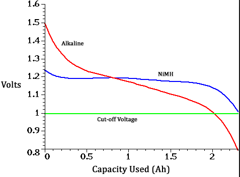
    @Igor-Katkov Your AA batteries will be as good as dead before these drop below the nrf24 minimum voltage (1.9V). See below the graph for one cell. If the arduino survives depends on hardware/ fuse-settings.

    0_1455694674730_upload-9c67f65a-394a-4e60-a5fb-e25d0d8d2ba3


  • OK, so I tried with AA cells, no regulators.
    Plain and simple. TMRh20 lib.
    Not any better.
    I then tried with a chunk of bare copper wire 83mm long, soldered to the end of that curly PCB antenna - not any better either.
    Not sure what might I've done wrong. Layout is pretty simple
    image of nrf24 transmitter
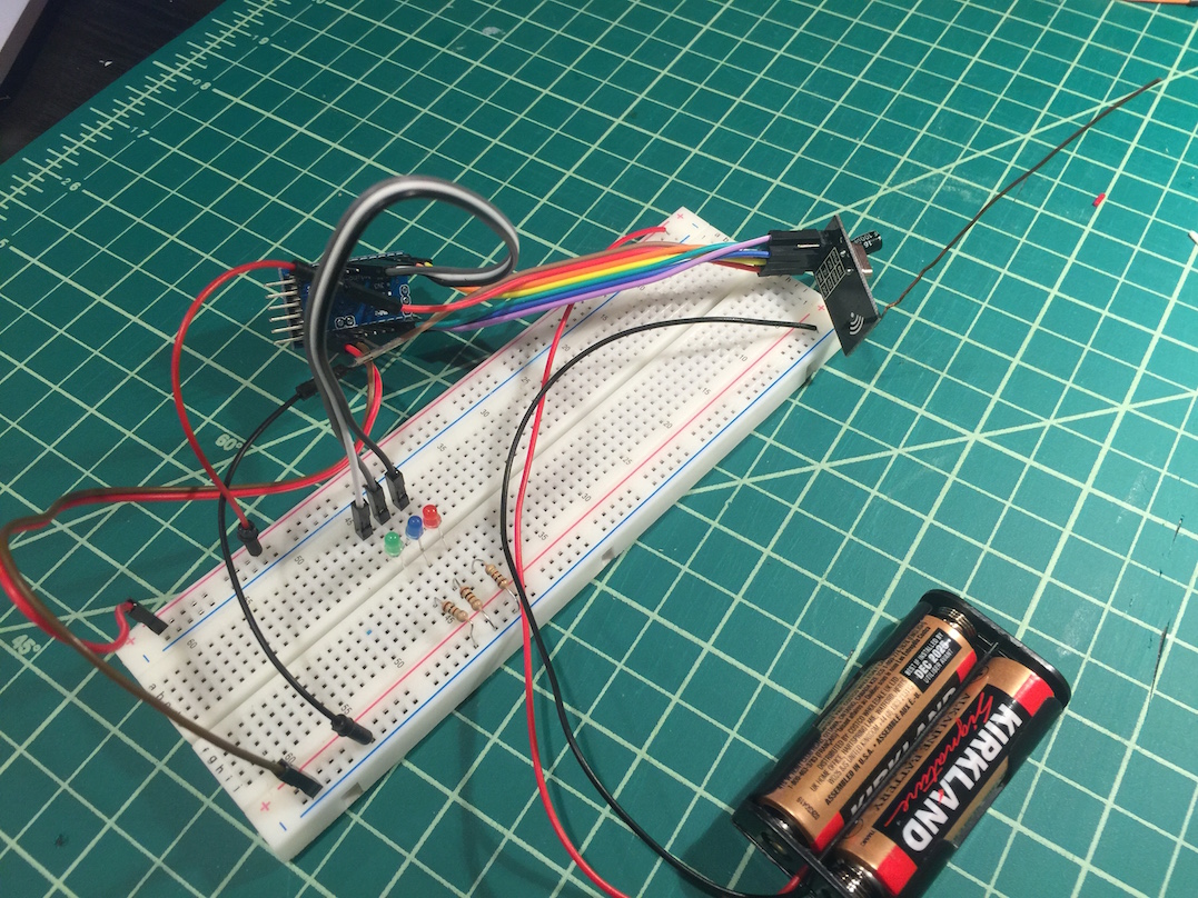
    Voltage with load is 3.1V, current never goes above 19.2mA
    image of multimeter

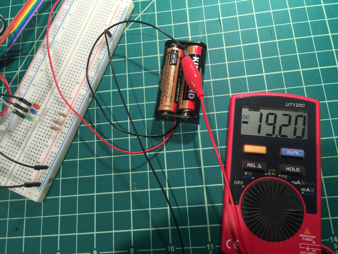
    I tried with direct line of sight, range has doubled to say 20m, but again - nothing to write home about.


  • [Update for future generation]
    I think I found my issue. It was the large transceiver see image below, with power amplifier and external antenna.
    Once I replaced both receiver and transmitter with identical units, range got significantly better.
    60m clear sight and almost whole house through multiple walls.

    For whatever reason small unit can't hear ACK from the PA unit. I tried to reduce power on the PA end to

     radio.setPALevel(RF24_PA_MIN); 
    

    but it did not seem to have any effect. My best guess now is that oscillator on the PA unit is slightly off. PCB antenna unit is battery powered.
    Power source to arduino UNO that drives PA unit is good, 5V less that 2mV ripple. The transceiver is powered via 3V3 output (onboard regulator) of UNO though, could it be the problem?


  • @Igor-Katkov said:
    The transceiver is powered via 3V3 output (onboard regulator) of UNO though, could it be the problem?

    Yes. But depends on which onboard regulator is used on your UNO.
    Also have an look here: http://forum.mysensors.org/topic/3168/long-range-transmission/27


  • Admin

    @Igor-Katkov said:

    I think I found my issue. It was the large transceiver see image below, with power amplifier and external antenna.

    I have had issues with my NRF radio like the one you mention here. I'm not sure about range issues but it totally stopped my Z-Wave network from communicating. It was easier for me to just use one of the smaller radios instead of doing further troubleshooting. I know there are some other threads (that I can't think of off the top of my head) where users have found that shielding it has helped. Also, as @Oitzu said, try powering it from a separate 3.3v source instead of from the Uno.


  • @petewill about shielding: you should have looked on the link http://blog.blackoise.de/2016/02/fixing-your-cheap-nrf24l01-palna-module/ . I explained it that often that i decided to write a blog article about it. 😛


  • Admin

    @Oitzu Awesome! I have one of these sitting in a drawer because of all the issues it caused me. 🙂 I may need to pull it out and try your method one of these days. For now I have been getting by with the external hack but I'm sure I'll want further range at some point...


  • @petewill great to hear. Let me know if you are successful. 🙂


  • This is great info. I actually had great luck with the chip antenna version with a mini pro and an UNO, and the range I wanted was just not there. I moved to the one with the PA+ ext antenna, and having a strange issue. If I swap out the chip antenna version for the PA+ ext antenna version on the mini pro, it only sends packets if I am physically touching the nRF board itself with my finger. The one connected to the UNO does not have this issue. It seems to be grounded sufficiently (only the GND pin on the nRF connector), and I changed the power source from the FTDI module to a separate 3.4V source with no difference in this behavior. Any ideas?


  • @pkjjneal said:
    it only sends packets if I am physically touching the nRF board itself with my finger.

    Also read: http://blog.blackoise.de/2016/02/fixing-your-cheap-nrf24l01-palna-module/
    Its a typical behaviour i observed on badly shielded modules.


  • I'm also getting poor range (Around 5m) and have tried most of the tricks. One thing with the homemade antenna from the video, which direction should the antenna be pointing?


  • Typically you point it up. It gives you vertical polarization.
    You point both transmitter and received wire antennas same directions.
    It's possible that your chips are at fault, if non of other tricks worked (capacitors, clear power, enough current, short wires, lo-noise rf spectrum channel) try other transceivers.


  • @Oitzu So I covered the nRF module in plastic and foil to create the shield. Previously, I had to touch a specific part of the board. Now I just touch any part of the foil, and it starts working. Makes sense, but I still cannot get transmissions without touching with my finger. I did try grounding the foil to the Arduino ground, but no change. The behavior makes me think I am on the correct path. Any other suggestions?


  • @pkjjneal would try to let the foil touch the ground from the antenna socket.
    Grounding the foil on the arduino probably creates a ground loop.

    May also try to add a filter.


  • @Oitzu
    I though antenna ground and MCU ground is the same thing


  • @Igor: Yes, that is right, but you are possible creating a ground loop.
    Grounding something should ever be as short as possible, because also in the GND wires electrical charges can build up and create interferences.


  • @Igor-Katkov said:

    It's possible that your chips are at fault, if non of other tricks worked (capacitors, clear power, enough current, short wires, lo-noise rf spectrum channel) try other transceivers.

    I've tried the cling wrap and tin foil trick - this seems to have worked. Was getting 5m or so, now I"m getting constant readings from one side of the house to the other (through multiple walls!). 20m

    Update: Just as I posted this the sensor stopped working 😞

    I'm really having major reliability issues with these sensors and am thinking of scrapping them altogether now. Its a pity these are such a hit and miss affair.


  • @gmccarthy

    My guess is if the sensors work and suddenly stop, you have something else interfering with the radios. Could be a microwave, AC unit, etc.

    I about gave up on this project last year. I had several units built that worked fine and then one day all of them quit. After several frustrating weeks, I discovered my wifi router somehow was interfering with the units. It was an old unit and I needed to replace it. After it was gone, everything went back to working correctly.


  • @gmccarthy don't give up. You seem to be on the right track and already got great results. 👍

    Maybe go bare bones and try the rf24 scanner,
    https://maniacbug.github.io/RF24/scanner_8pde-example.html
    to find the best nrf24 channel for your. 🙂


  • @Oitzu said:

    @gmccarthy don't give up. You seem to be on the right track and already got great results.
    Maybe go bare bones and try the rf24 scanner

    Thanks. This looks interesting. Will give it a shot.


  • @gmccarthy As far as I know, NRF channels above 100 should not have interference from Wifi 2.4 Ghz. I was getting 2-3 meters at best. I changed the channel to 110 and corrected the power supply a little. I am yet to implement cling wrap.

    I get 10-15 meters between two standard modules inside an apartment. The apartment is like a faraday cage and sometimes I cannot get wifi on the outer extremes while router is in the middle. I am getting sensor readings from one end to the other now, passing through the area where I have the router. So, I think interference is critical in distance.


  • Hardware Contributor

    Hey guys I seem to have similar (but even worse) problems here. I am building a rgbwController and have huge problems connecting that to my gateway although it's only ~3m and no obstacle away.
    I am using 4,7uF caps on both sides. Stepdown from 12V + another cap on the rgbwController's side and the arduino uno's 3.3V on the other side. I also tried another external 3.3V power source here (but that did not help either).
    I tried changing the channel to 111 but that seems to have made it even worse.

    Any ideas how to debug that or what to change?
    It's really sad to have the setup up and running and then being unable to really use it due to radio problems ;(


  • @LastSamurai Which nrf24l01+ modules are you using on which side?
    Whats the typical error pattern you get? (Failed transmission from gw to node or from node to gw?)
    Need to know your exact construction, before guessing what could be wrong.


  • Hardware Contributor

    @Oitzu
    I am using the "standard" ones on both sides ("sodial" ones. I think these). My logs from the controller from my thread look like this:

    0;0;3;0;9;send: 0-0-123-123 s=1,c=1,t=2,pt=0,l=1,sg=0,st=fail:1
    0;0;3;0;9;read: 123-123-0 s=1,c=1,t=2,pt=0,l=1,sg=0:1
    123;1;1;1;2;1
    0;0;3;0;9;send: 0-0-123-123 s=1,c=1,t=2,pt=0,l=1,sg=0,st=fail:1
    0;0;3;0;9;send: 0-0-123-123 s=1,c=1,t=2,pt=0,l=1,sg=0,st=fail:0
    0;0;3;0;9;send: 0-0-123-123 s=1,c=1,t=2,pt=0,l=1,sg=0,st=fail:1
    0;0;3;0;9;send: 0-0-123-123 s=1,c=1,t=2,pt=0,l=1,sg=0,st=fail:1
    0;0;3;0;9;send: 0-0-123-123 s=1,c=1,t=2,pt=0,l=1,sg=0,st=fail:0
    0;0;3;0;9;send: 0-0-123-123 s=1,c=1,t=2,pt=0,l=1,sg=0,st=ok:1
    0;0;3;0;9;send: 0-0-123-123 s=1,c=1,t=2,pt=0,l=1,sg=0,st=fail:0
    0;0;3;0;9;read: 123-123-0 s=1,c=1,t=2,pt=0,l=1,sg=0:0
    123;1;1;1;2;0
    0;0;3;0;9;send: 0-0-123-123 s=1,c=1,t=2,pt=0,l=1,sg=0,st=fail:1
    0;0;3;0;9;send: 0-0-123-123 s=1,c=1,t=2,pt=0,l=1,sg=0,st=ok:0
    0;0;3;0;9;read: 123-123-0 s=1,c=1,t=2,pt=0,l=1,sg=0:0
    123;1;1;1;2;0
    0;0;3;0;9;send: 0-0-123-123 s=1,c=1,t=2,pt=0,l=1,sg=0,st=ok:1
    0;0;3;0;9;read: 123-123-0 s=1,c=1,t=2,pt=0,l=1,sg=0:1
    123;1;1;1;2;1
    0;0;3;0;9;send: 0-0-123-123 s=1,c=1,t=2,pt=0,l=1,sg=0,st=fail:0
    0;0;3;0;9;read: 123-123-0 s=1,c=1,t=2,pt=0,l=1,sg=0:0
    123;1;1;1;2;0
    0;0;3;0;9;send: 0-0-123-123 s=1,c=1,t=2,pt=0,l=1,sg=0,st=fail:1
    0;0;3;0;9;send: 0-0-123-123 s=1,c=1,t=2,pt=0,l=1,sg=0,st=fail:0
    0;0;3;0;9;send: 0-0-123-123 s=1,c=1,t=2,pt=0,l=1,sg=0,st=fail:1
    0;0;3;0;9;send: 0-0-123-123 s=1,c=1,t=2,pt=0,l=1,sg=0,st=fail:0
    0;0;3;0;9;send: 0-0-123-123 s=1,c=1,t=2,pt=0,l=1,sg=0,st=fail:1
    0;0;3;0;9;send: 0-0-123-123 s=1,c=1,t=2,pt=0,l=1,sg=0,st=fail:0
    0;0;3;0;9;send: 0-0-123-123 s=1,c=1,t=2,pt=0,l=1,sg=0,st=fail:1
    0;0;3;0;9;send: 0-0-123-123 s=1,c=1,t=2,pt=0,l=1,sg=0,st=fail:0
    0;0;3;0;9;read: 123-123-0 s=1,c=1,t=2,pt=0,l=1,sg=0:0
    123;1;1;1;2;0
    0;0;3;0;9;send: 0-0-123-123 s=1,c=1,t=2,pt=0,l=1,sg=0,st=fail:1
    0;0;3;0;9;send: 0-0-123-123 s=1,c=1,t=2,pt=0,l=1,sg=0,st=ok:0
    0;0;3;0;9;read: 123-123-0 s=1,c=1,t=2,pt=0,l=1,sg=0:0
    123;1;1;1;2;0
    0;0;3;0;9;send: 0-0-123-123 s=1,c=1,t=2,pt=0,l=1,sg=0,st=fail:1
    0;0;3;0;9;read: 123-123-0 s=1,c=1,t=2,pt=0,l=1,sg=0:1
    123;1;1;1;2;1
    0;0;3;0;9;send: 0-0-123-123 s=1,c=1,t=2,pt=0,l=1,sg=0,st=fail:1
    0;0;3;0;9;send: 0-0-123-123 s=1,c=1,t=41,pt=0,l=9,sg=0,st=fail:#00000
    0;0;3;0;9;read: 123-123-0 s=1,c=1,t=41,pt=0,l=9,sg=0:#000000FF
    123;1;1;1;41;#000000FF
    0;0;3;0;9;send: 0-0-123-123 s=1,c=1,t=3,pt=0,l=3,sg=0,st=fail:100
    0;0;3;0;9;send: 0-0-123-123 s=1,c=1,t=2,pt=0,l=1,sg=0,st=fail:0
    0;0;3;0;9;read: 123-123-0 s=1,c=1,t=2,pt=0,l=1,sg=0:0
    123;1;1;1;2;0
    0;0;3;0;9;send: 0-0-123-123 s=1,c=1,t=2,pt=0,l=1,sg=0,st=fail:1
    0;0;3;0;9;read: 123-123-0 s=1,c=1,t=2,pt=0,l=1,sg=0:1
    123;1;1;1;2;1
    

    Sometimes I get a fail message but the lights are reacting (so I guess the ack didn't reach the gateway). I wasn't able to debug the rgbw controller in its position yet because it's sitting on top of a cupboard.
    If you need more infos just tell me.

    I'll try out another arduino as gateway later.

    PS according to this post they might be "fake" though 😉 Although others seemed to have used them for mysensors too (comments)


  • Hardware Contributor

    Something seems to be off with the controller. I tried the same code on another arduino uno and it worked just fine. A little less distance perhaps but no errors at all. I'll try to do some hardware testing and measuring tomorrow.


  • @LastSamurai also keep in mind that if you are using the LM2596 buck converter that you need to use a post ripple filter.
    I explained that here: http://blog.blackoise.de/2016/03/building-a-lc-filter-for-your-nrf24l01-palna-module/.


  • Hardware Contributor

    @Oitzu Thanks for the hint! That might actually have been a reason why it worked for some time and then stoped, right? I have ordered the components needed and will test it soon.
    I don't actually use the LM2596 modules but these smaller ones but I guess they use similar parts.

    Did you have similar issues?


  • @LastSamurai can't really say for this modules.
    The datasheet for the LM2596 says you should use a post ripple filter for low noise, because it generates sawtooth ripple at its switching frequency (150khz). The china-clones of the lm2596 seem to be even worse generating even greater ripple with 50khz.

    Whats the ic on the mini dc-dc converter called? The ebay offer says it has a output ripple of 30mV bute more then often these values are the best case. Maybe a datasheets is available.


  • It would be so useful to be able to measure the supply voltages with an oscilloscope. So far all my transmission problems have been related to the power supplies. Only after using a scope I fully realized that. No more freezing or poor function of the nodes.

    Also, using a brand supply doesn't necessarily mean a clean signal. This (again) is an illustrative post about USB supplies, worth to take a look at:
    http://www.righto.com/2012/10/a-dozen-usb-chargers-in-lab-apple-is.html


  • It would be so useful to be able to measure the supply voltages with an oscilloscope. So far all my transmission problems have been related to the power supplies. Only after using a scope I fully realized that. No more freezing or poor function of the nodes.

    You are totally right! Unfortunately i also don't own a oscilloscope. But a cheaper usb oscilloscope is on my need to have list because of a all the trouble and testing i had with this...


  • @Oitzu DSO138 scope is like $25 from aliexpress


  • @Igor-Katkov said:

    DSO138

    Was thinking of something like the Hantek 6022BE. Most EE guys would say "eh... crap", but oh well.. it's just a hobby and i'm not willing to pay hundreds of dollars for it. 😄


  • One might think that to measure ripple noise of $2 Chinese power supply ~$70 unit is an overkill 🙂


  • @Igor-Katkov eh... now you just sound like my gf. 😛
    No, you're right. But it may come handy in some other situations. 🙂


  • Hero Member

    @Nuubi My two cents.. I have been measuring (with a scope ;)) quite a lot of power supplies and have come to the conclusion that most (inexpensive) switching power regulators (buck & boost) should be avoided when a clean supply is needed. All (or most) of these just not have enough filtering (LC) for the switching frequency. So go for a 'linear' version (for buck/ step-down), especially for the radio. Also PIR sensors are very sensitive.
    0_1458066567182_upload-0289df5e-247a-4989-ac3b-d27025c2dc2b

    Lucky for us most MySensors circuits need very little power, so the efficiency of a linear converter (for buck) is sufficient in most cases.

    from digikey

    0_1458066504021_upload-358f1f5f-6bbe-4b43-bd08-2bd059779fb3

    or use a linear converter as "second stage"

    0_1458066851833_upload-73d535e4-fb0d-434e-9ca6-2dd04ddc308e


  • Hardware Contributor

    @Oitzu Looks like the chips are these.

    Btw I am using a cheap DS201 and I am happy with it for most cases. Sometimes I wish for a second channel but you can carry it around which is a big plus 🙂

    @AWI I have to convert 12V to 3.3V which is a big jump. So you think a linear regulator would work here? Something like a LM 1117 T3,3? Doesn't that get too hot if I constantly power the arduino, the radio and potentially a sensor?
    PS has someone tried this? Otherwise the second stage LDO (something small, smd) would be an idea too.


  • Hero Member

    @LastSamurai No problem at all if you solder it on a copper plane. Most sensor circuits take less than 20mA.

    I actually use the 662K LDO as a second stage with a step-up converter, works like a charm.

    For the LM1117 (=not a real Low Dropout) the input voltage can be up to 20V.

    0_1458067307906_upload-98cbdf28-e608-49ab-8e4b-f884c739a5d4


  • @LastSamurai https://www.adafruit.com/datasheets/MP2307_r1.9.pdf
    seems to be more complete and well.. a filter or a second stage would be recommend.

    @AWI i'm actually have a project running from 12v lead batteries, best way would be to use 2 stages?
    ATM i'm using an additional lc-filter to get the ripple out.


  • Hero Member

    @Oitzu In your case ...
    5 pcs complete linear adjustable neglectable ripple and cooled converter


  • @AWI hm... okay. Will probably order a few and test them. 👍


  • Hardware Contributor

    Could you perhaps actually use the onboard voltage regulator of the pro mini for powering the mini + nrf + random sensor? That would be the easiest + cheapest methode. Perhaps add one cap.


  • @LastSamurai depends on the used onboard regulator and the used nrf + random sensor.
    But yes, this works also, most of the time on non pa/lna modules.


  • @Oitzu in case you are looking for a cheap DIY osci, I'm going to build a Girino (http://www.instructables.com/id/Girino-Fast-Arduino-Oscilloscope/?ALLSTEPS) when I find the time. There is also an frontent on github (https://github.com/Chatanga/Girinoscope/tree/v1.0.1-beta). Seems to be quite simple and with very cheap hardware, so don't expect too much. But to have a look at some voltage levels and ripple it might be ok.
    And when using it with a battery powered laptop you should be even ok with potential-free measurements.


  • This post is deleted!


  • @epierre

    I'd be surprised if the existing on board antenna is anything else than a 1/4 wave length of the center frequency for the NRF24L01 module. Therefore I BELIEVE that the right thing would be to extend it with antother 3/4 to make it a full wave length.

    If you run it at the default MySensors frequency which is 2476 MHz, a full wave length is 121 mm. Therefore I'd assume that adding another 91 mm to the existing antenna would be the correct length. I haven't tried it yet though but I will.

    Cheers!


  • I'm currently in the process of trying to figure out why one of my battery powered nodes isn't working very well with a newly purchased NRF24L01+PA+LNA module. I've shielded it as described in earlier posts. There is plenty of pure power in the batteries.

    Just as in the case for @pkjjneal it works well only if I'm touching the antenna with a finger.

    I decided to look inside the antenna:
    0_1533729640287_DSC_1916.JPG

    As you see above, it starts with an antenna cable that leads to a half wave dipole (where the antenna element is of about 1/4 wave length) and there is a "sleeve balun" going back over the cable . I can find no ground plane though. The problem that I can see is that the antenna length is 27 mm where it should optimally be 28.8 mm.

    Now, if I remove the antenna completely my node works quite well. At least better than if I use the original antenna unmodified.

    If I insert a wire (DIY antenna made by a paper clip) extending 121 mm out of the antenna sockets forming a full wave length antenna things work great.

    I also modified the original antenna so that the antenna element becomes 28.8 mm. It works a bit better but it's far from perfect and communication errors are shown in the log.

    As the final test, I added a nice ground plane to the original antenna and now it works really perfect!
    0_1533729823658_DSC_1917.JPG

    So what can I learn from this?

    My test rig is an EasyPCB powered with batteries. I'm quite sure that my NRF24L01+PA+LNA module used in another scenario, for example connected to a Arduino Nano fed by a FTDI connector could actually work. It's because it would create a different environment. The antenna will work in relation to what it's connected to, shielding the grounding, and surrounding objects. Capacitive and inductive reactances are involved in mysterious ways.

    Anyway. My conclusion is that the two original antennas I have are not working very good. They obviously have the wrong length just a little bit, and I'd say that the the way the antenna is constructed with the sleeve balun and no ground plane, doesn't seem to work well. At least not here.

    I'll do some more experimenting with making my own antennas. Starting with taking apart an original antenna is not so bad, I can solder anything (solderable) onto the cable.

    Cheers!

    From wikipedia:

    Sleeve balun
    At VHF frequencies, a sleeve balun can also be built to remove feeder radiation.

    Another narrow-band design is to use a λ/4 length of metal pipe. The coaxial cable is placed inside the pipe; at one end the braid is wired to the pipe while at the other end no connection is made to the pipe. The balanced end of this balun is at the end where no connection is made to the pipe. The λ/4 conductor acts as a transformer, converting the zero impedance at the short to the braid into an infinite impedance at the open end. This infinite impedance at the open end of the pipe prevents current flowing into the outer coax formed by the outside of the inner coax shield and the pipe, forcing the current to remain in the inside coax.


Log in to reply
 

Suggested Topics

  • 87
  • 2
  • 6
  • 3
  • 7
  • 8

1
Online

11.2k
Users

11.1k
Topics

112.5k
Posts