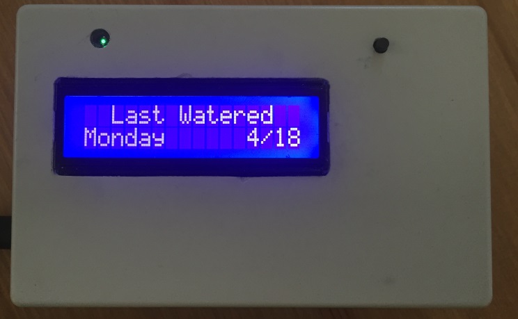
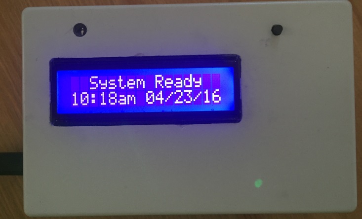
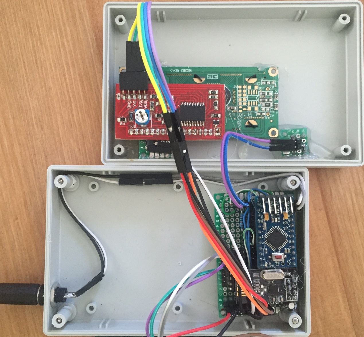
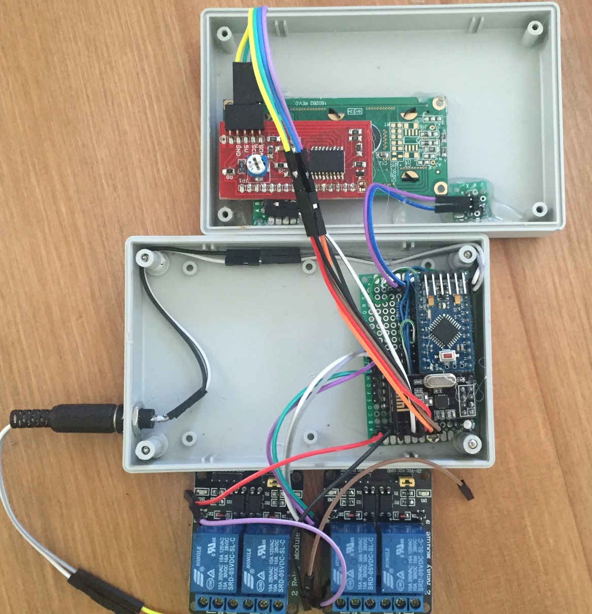
Irrigation Controller (up to 16 valves with Shift Registers)
-
@epierre can you please link to the post?
-
-
@epierre He meant in the sense that it does not display or use it for anything. he said there "it is used to store/retrieve variables". The thread was about the option to show the vars as part of the sensor output. for storing and retrieving, it works.... verified.... I might get annoyed enough to add to the code that the lua script can also retrieve these vars and then it would be sweet.....
-
ok good although it was not explicit... now I'll have to go back to him about water meter that heavily use V_VARs but is recognized.... as a power meter...
-
Hello
And thx for a nice forum, I did build the irrigation controller and tried to connect it to Domoticz. Everything just seems fine, LCD works, push button works and I can turn on the irrigation from Domoticz and it shows in the LCD.But the problem is that it doesn't switch the relays on, it just says "no valve time" and then go watering cycle complete.
Any suggestions on what the problem might be...... Domoticz?
Regards
-
I don't have Domoticz but I suspect that the callback isn't functioning.
try populating the array with the desired times for each sequence. replace this:
int allZoneTime [NUMBER_OF_VALVES + 1]; int valveSoloTime [NUMBER_OF_VALVES + 1];
with something like this:
int allZoneTime [NUMBER_OF_VALVES + 1] = {0, 10, 10, 10, 5,<... how many valves you have with zero in the first position>} ; int valveSoloTime [NUMBER_OF_VALVES + 1] = {0, 5, 5, 5, 5,<... how many valves you have with zero in the first position>};
This will load in the times that the program uses as your 'default' values. Then, you can check with Domoticz experts on getting the V_VAR variables working.
-
Thx Bulldog
I will check asap and get back with the result.Regards
-
Hi
I tried the code but it didn't compile, and I'm not good enough to be sure whats wrong.I did try change the code and I did get it to compile, but I don't know if I got it right. You can see the lame attempt below the colored line.
-
Clearly you understand that you are to put the times for each of the valve zones, led by a zero into the array, and not copy my verbatim instructions...
How many valves do you have? You need that many (plus one) integer numbers separated by commas...
Example 8 valves:
...= {0,5,5,5,5,5,5,5,5};
You've commented out the wrong lines.
-
Thx for the quick answer
I use 4 valves atm, I tried your suggestion but it seems it wont work for me.
Regards
-
The inserted values in the array works from start, but it looks like the irrigation controller immediately starts to request valve data from the controller for variable1 and 2. As we cant set variable1 and 2 in Domoticz I guess it returns 0 and overwrite the inserted values in the arrays...or is it anything else happening?
Initialising... Turning All Valves Off... Unable to sync with the RTC Checking EEPROM for stored date: Retreiving last run time from EEPROM... send: 7-7-0-0 s=255,c=0,t=17,pt=0,l=3,sg=0,st=ok:1.5 send: 7-7-0-0 s=255,c=3,t=6,pt=1,l=1,sg=0,st=ok:0 read: 0-0-7 s=255,c=3,t=6,pt=0,l=1,sg=0:M sensor started, id=7, parent=0, distance=1 send: 7-7-0-0 s=255,c=3,t=11,pt=0,l=11,sg=0,st=ok:MySprinkler send: 7-7-0-0 s=255,c=3,t=12,pt=0,l=6,sg=0,st=ok:2.0nsr send: 7-7-0-0 s=0,c=0,t=3,pt=0,l=0,sg=0,st=ok: send: 7-7-0-0 s=1,c=0,t=3,pt=0,l=0,sg=0,st=ok: send: 7-7-0-0 s=2,c=0,t=3,pt=0,l=0,sg=0,st=ok: send: 7-7-0-0 s=3,c=0,t=3,pt=0,l=0,sg=0,st=ok: send: 7-7-0-0 s=4,c=0,t=3,pt=0,l=0,sg=0,st=ok: Sensor Presentation Complete Ready... Calling for Valve 0 Data... send: 7-7-0-0 s=0,c=2,t=24,pt=0,l=0,sg=0,st=ok: read: 0-0-7 s=0,c=2,t=24,pt=0,l=0,sg=0: Recieved variable1 valve:0 = 0 send: 7-7-0-0 s=0,c=2,t=25,pt=0,l=0,sg=0,st=ok: read: 0-0-7 s=0,c=2,t=25,pt=0,l=0,sg=0: Recieved variable2 valve:0 = 0 send: 7-7-0-0 s=0,c=2,t=26,pt=0,l=0,sg=0,st=ok: read: 0-0-7 s=0,c=2,t=26,pt=0,l=0,sg=0: No Name Recieved for zone 0 Calling for Valve 1 Data... send: 7-7-0-0 s=1,c=2,t=24,pt=0,l=0,sg=0,st=ok: read: 0-0-7 s=1,c=2,t=24,pt=0,l=0,sg=0: Recieved variable1 valve:1 = 0 New Zone Times Recieved... Zone 1 individual time: 1 group time: 0 Zone 2 individual time: 1 group time: 1 Zone 3 individual time: 1 group time: 1 Zone 4 individual time: 1 group time: 1 send: 7-7-0-0 s=1,c=2,t=25,pt=0,l=0,sg=0,st=ok: read: 0-0-7 s=1,c=2,t=25,pt=0,l=0,sg=0: Recieved variable2 valve:1 = 0 New Zone Times Recieved... Zone 1 individual time: 0 group time: 0 Zone 2 individual time: 1 group time: 1 Zone 3 individual time: 1 group time: 1 Zone 4 individual time: 1 group time: 1 send: 7-7-0-0 s=1,c=2,t=26,pt=0,l=0,sg=0,st=ok: read: 0-0-7 s=1,c=2,t=26,pt=0,l=0,sg=0: No Name Recieved for zone 1 Calling for Valve 2 Data... send: 7-7-0-0 s=2,c=2,t=24,pt=0,l=0,sg=0,st=ok: read: 0-0-7 s=2,c=2,t=24,pt=0,l=0,sg=0: Recieved variable1 valve:2 = 0 New Zone Times Recieved... Zone 1 individual time: 0 group time: 0 Zone 2 individual time: 1 group time: 0 Zone 3 individual time: 1 group time: 1 Zone 4 individual time: 1 group time: 1 send: 7-7-0-0 s=2,c=2,t=25,pt=0,l=0,sg=0,st=ok: read: 0-0-7 s=2,c=2,t=25,pt=0,l=0,sg=0: Recieved variable2 valve:2 = 0 New Zone Times Recieved... Zone 1 individual time: 0 group time: 0 Zone 2 individual time: 0 group time: 0 Zone 3 individual time: 1 group time: 1 Zone 4 individual time: 1 group time: 1 send: 7-7-0-0 s=2,c=2,t=26,pt=0,l=0,sg=0,st=ok: read: 0-0-7 s=2,c=2,t=26,pt=0,l=0,sg=0: No Name Recieved for zone 2 Calling for Valve 3 Data... send: 7-7-0-0 s=3,c=2,t=24,pt=0,l=0,sg=0,st=ok: read: 0-0-7 s=3,c=2,t=24,pt=0,l=0,sg=0: Recieved variable1 valve:3 = 0 New Zone Times Recieved... Zone 1 individual time: 0 group time: 0 Zone 2 individual time: 0 group time: 0 Zone 3 individual time: 1 group time: 0 Zone 4 individual time: 1 group time: 1 send: 7-7-0-0 s=3,c=2,t=25,pt=0,l=0,sg=0,st=ok: read: 0-0-7 s=3,c=2,t=25,pt=0,l=0,sg=0: Recieved variable2 valve:3 = 0 New Zone Times Recieved... Zone 1 individual time: 0 group time: 0 Zone 2 individual time: 0 group time: 0 Zone 3 individual time: 0 group time: 0 Zone 4 individual time: 1 group time: 1 send: 7-7-0-0 s=3,c=2,t=26,pt=0,l=0,sg=0,st=ok: read: 0-0-7 s=3,c=2,t=26,pt=0,l=0,sg=0: No Name Recieved for zone 3 Calling for Valve 4 Data... send: 7-7-0-0 s=4,c=2,t=24,pt=0,l=0,sg=0,st=ok: read: 0-0-7 s=4,c=2,t=24,pt=0,l=0,sg=0: Recieved variable1 valve:4 = 0 New Zone Times Recieved... Zone 1 individual time: 0 group time: 0 Zone 2 individual time: 0 group time: 0 Zone 3 individual time: 0 group time: 0 Zone 4 individual time: 1 group time: 0 send: 7-7-0-0 s=4,c=2,t=25,pt=0,l=0,sg=0,st=ok: read: 0-0-7 s=4,c=2,t=25,pt=0,l=0,sg=0: Recieved variable2 valve:4 = 0 New Zone Times Recieved... Zone 1 individual time: 0 group time: 0 Zone 2 individual time: 0 group time: 0 Zone 3 individual time: 0 group time: 0 Zone 4 individual time: 0 group time: 0 send: 7-7-0-0 s=4,c=2,t=26,pt=0,l=0,sg=0,st=ok: read: 0-0-7 s=4,c=2,t=26,pt=0,l=0,sg=0: No Name Recieved for zone 4
-
try commenting out this in
setup()
:/* for (byte i = 0; i <= NUMBER_OF_VALVES; i++) { pinMode(relayPin[i], OUTPUT); lcd.print(F(" Updating ")); lcd.setCursor(0, 1); lcd.print(F(" Valve Data: ")); lcd.print(i); boolean flashIcon = false; DEBUG_PRINT(F("Calling for Valve ")); DEBUG_PRINT(i); DEBUG_PRINTLN(F(" Data...")); while (gw.process() == false) { lcd.setCursor(15, 0); flashIcon = !flashIcon; flashIcon ? lcd.write(byte(1)) : lcd.print(F(" ")); gw.request(i, V_VAR1); delay(100); } while (gw.process() == false) { lcd.setCursor(15, 0); flashIcon = !flashIcon; flashIcon ? lcd.write(byte(1)) : lcd.print(F(" ")); gw.request(i, V_VAR2); delay(100); } while (gw.process() == false) { lcd.setCursor(15, 0); flashIcon = !flashIcon; flashIcon ? lcd.write(byte(1)) : lcd.print(F(" ")); gw.request(i, V_VAR3); delay(100); } }*/
and this in
loop()
://goGetValveTimes();
That will disable those callbacks and you should be OK with a HardCoded time table for the valves and valve names.
-
Thx Bulldog for all the help, everything seems to be working as it should now.
Keep up the good work
Updated code for Domoticz.
/* MySprinkler for MySensors Arduino Multi-Zone Sprinkler Control May 31, 2015 *** Version 2.0 *** Upgraded to http://MySensors.org version 1.4.1 *** Expanded for up to 16 Valves *** Setup for active low relay board or comment out #define ACTIVE_LOW to switch to active high *** Switch to bitshift method vs byte arrays *** Changed RUN_ALL_ZONES Vera device to 0 (was highest valve) *** Added optional LCD display featuring remaining time, date last ran & current time *** Features 'raindrop' and 'clock' icons which indicate sensor is updating valve data and clock respectively *** Added single pushbutton menu to manually select which program to run (All Zones or a Single Zone) *** Added option of naming your Zones programmatically or with Vera (V_VAR3 used to store names) Utilizing your Vera home automation controller and the MySensors.org gateway you can control up to a sixteen zone irrigation system with only three digital pins. This sketch will create NUMBER_OF_VALVES + 1 devices on your Vera controller This sketch features the following: * Allows you to cycle through All zones (RUN_ALL_ZONES) or individual zone (RUN_SINGLE_ZONE) control. * Use the 0th controller to activate RUN_ALL_ZONES (each zone in numeric sequence 1 to n) using Variable1 as the "ON" time in minutes in each of the vera devices created. * Use the individual zone controller to activate a single zone. This feature uses Variable2 as the "ON" time for each individual device/zone. * Connect according to pinout below and uses Shift Registers as to allow the MySensors standard radio configuration and still leave available digital pins * Turning on any zone will stop the current process and begin that particular process. * Turning off any zone will stop the current process and turn off all zones. * To push your new time intervals for your zones, simply change the variable on your Vera and your arduino will call to Vera once a minute and update accordingly. Variables will also be requested when the device is first powered on. * Pushbutton activation to RUN_ALL_ZONES, RUN_SINGLE_ZONE or halt the current program * LED status indicator PARTS LIST: Available from the MySensors store - http://www.mysensors.org/store/ * Relays (8 channel) * Female Pin Header Connector Strip * Prototype Universal Printed Circuit Boards (PCB) * NRF24L01 Radio * Arduino (I used a Pro Mini) * FTDI USB to TTL Serial Adapter * Capacitors (10uf and .1uf) * 3.3v voltage regulator * Resistors (270 & 10K) * Female Dupont Cables * 1602 LCD (with I2C Interface) * LED * Push button * Shift Register (SN74HC595) * 2 Pole 5mm Pitch PCB Mount Screw Terminal Block * 3 Pole 5mm Pitch PCB Mount Screw Terminal Block * 22-24 gauge wire or similar (I used Cat5/Cat6 cable) * 18 gauge wire (for relay) * Irrigation Power Supply (24-Volt/750 mA Transformer) INSTRUCTIONS: * A step-by-step setup video is available here: http://youtu.be/l4GPRTsuHkI * After assembling your arduino, radio, decoupling capacitors, shift register(s), status LED, pushbutton LCD (I2C connected to A4 and A5) and relays, and load the sketch. * Following the instructions at https://MySensors.org include the device to your MySensors Gateway. * Verify that each new device has a Variable1, Variable2 and Variable3. Populate data accordingly with whole minutes for the RUN_ALL_ZONES routine (Variable1) and the RUN_SINGLE_ZONE routines (Variable 2). The values entered for times may be zero and you may use the defaulet zone names by leaving Variable3 blank. * Once you have entered values for each zone and each variable, save the settings by pressing the red save button on your Vera. * Restart your arduino; verify the settings are loaded into your arduino with the serial monitor; the array will be printed on the serial monitor. * Your arduino should slow-flash, indicating that it is in ready mode. * There are multiple debug serial prints that can be monitored to assure that it is operating properly. * ***THIS SHOULD NO LONGER BE NEEDED*** The standard MySensors library now works. https://bitbucket.org/fmalpartida/new-liquidcrystal/downloads for the I2C library, or use yours Contributed by Jim (BulldogLowell@gmail.com) with much contribution from Pete (pete.will@mysensors.org) and is released to the public domain */ // #include <Wire.h> #include <Time.h> #include <MySensor.h> #include <SPI.h> #include <LiquidCrystal.h> #include <LiquidCrystal_I2C.h> // #define NUMBER_OF_VALVES 4 // Change this to set your valve count up to 16. #define VALVE_RESET_TIME 7500UL // Change this (in milliseconds) for the time you need your valves to hydraulically reset and change state #define RADIO_ID AUTO // Change this to fix your Radio ID or use Auto #define SKETCH_NAME "MySprinkler Domoticz" #define SKETCH_VERSION "2.0" // #define CHILD_ID_SPRINKLER 0 // //#define ACTIVE_LOW // comment out this line if your relays are active high // #define DEBUG_ON // comment out to supress serial monitor output // #ifdef ACTIVE_LOW #define BITSHIFT_VALVE_NUMBER ~(1U << (valveNumber-1)) #define ALL_VALVES_OFF 0xFFFF #else #define BITSHIFT_VALVE_NUMBER (1U << (valveNumber-1)) #define ALL_VALVES_OFF 0U #endif // #ifdef DEBUG_ON #define DEBUG_PRINT(x) Serial.print(x) #define DEBUG_PRINTLN(x) Serial.println(x) #define SERIAL_START(x) Serial.begin(x) #else #define DEBUG_PRINT(x) #define DEBUG_PRINTLN(x) #define SERIAL_START(x) #endif // typedef enum { STAND_BY_ALL_OFF, RUN_SINGLE_ZONE, RUN_ALL_ZONES, CYCLE_COMPLETE, ZONE_SELECT_MENU } SprinklerStates; // SprinklerStates state = STAND_BY_ALL_OFF; SprinklerStates lastState; byte menuState = 0; unsigned long menuTimer; byte countDownTime = 10; // int allZoneTime [NUMBER_OF_VALVES + 1]= {0, 1, 1, 1, 1}; // Insert values in min, 0 = all zone (always 0) this is a 4 chan relay int valveSoloTime [NUMBER_OF_VALVES + 1]= {0, 1, 1, 1, 1}; // Insert values in min, 0 = all zone (always 0) this is a 4 chan relay int valveNumber; int lastValve; unsigned long startMillis; const int ledPin = 5; const int waterButtonPin = 3; boolean buttonPushed = false; boolean showTime = true; boolean clockUpdating = false; boolean recentUpdate = true; const char *dayOfWeek[] = { "Null", "Sunday ", "Monday ", "Tuesday ", "Wednesday ", "Thursday ", "Friday ", "Saturday " }; // Name your Zones here or use Vera to edit them by adding a name in Variable3... String valveNickName[17] = { "All Zones", "Zone 1", "Zone 2", "Zone 3", "Zone 4", "Zone 5", "Zone 6", "Zone 7", "Zone 8", "Zone 9", "Zone 10", "Zone 11", "Zone 12", "Zone 13", "Zone 14", "Zone 15", "Zone 16" }; // time_t lastTimeRun = 0; //Setup Shift Register... const int latchPin = 8; const int clockPin = 4; const int dataPin = 7; // byte clock[8] = {0x0, 0xe, 0x15, 0x17, 0x11, 0xe, 0x0}; // fetching time indicator byte raindrop[8] = {0x4, 0x4, 0xA, 0xA, 0x11, 0xE, 0x0,}; // fetching Valve Data indicator // Set the pins on the I2C chip used for LCD connections: // addr, en,rw,rs,d4,d5,d6,d7,bl,blpol LiquidCrystal_I2C lcd(0x27, 2, 1, 0, 4, 5, 6, 7, 3, POSITIVE); // Set the LCD I2C address to 0x27 MySensor gw; // MyMessage msg1valve(CHILD_ID_SPRINKLER, V_LIGHT); MyMessage var1valve(CHILD_ID_SPRINKLER, V_VAR1); MyMessage var2valve(CHILD_ID_SPRINKLER, V_VAR2); // void setup() { SERIAL_START(115200); DEBUG_PRINTLN(F("Initialising...")); pinMode(latchPin, OUTPUT); pinMode(clockPin, OUTPUT); pinMode(dataPin, OUTPUT); pinMode(ledPin, OUTPUT); pinMode(waterButtonPin, INPUT_PULLUP); //pinMode(waterButtonPin, INPUT); attachInterrupt(1, PushButton, RISING); //May need to change for your Arduino model digitalWrite (ledPin, HIGH); DEBUG_PRINTLN(F("Turning All Valves Off...")); updateRelays(ALL_VALVES_OFF); //delay(5000); lcd.begin(16, 2); //(16 characters and 2 line display) lcd.clear(); lcd.backlight(); lcd.createChar(0, clock); lcd.createChar(1, raindrop); // //check for saved date in EEPROM DEBUG_PRINTLN(F("Checking EEPROM for stored date:")); delay(500); if (gw.loadState(0) == 0xFF); // EEPROM flag { DEBUG_PRINTLN(F("Retreiving last run time from EEPROM...")); for (int i = 0; i < 4 ; i++) { lastTimeRun = lastTimeRun << 8; lastTimeRun = lastTimeRun | gw.loadState(i + 1); // assemble 4 bytes into an ussigned long epoch timestamp } } gw.begin(getVariables, RADIO_ID, false); // Change 'false' to 'true' to create a Radio repeating node gw.sendSketchInfo(SKETCH_NAME, SKETCH_VERSION); for (byte i = 0; i <= NUMBER_OF_VALVES; i++) { gw.present(i, S_LIGHT); } DEBUG_PRINTLN(F("Sensor Presentation Complete")); // digitalWrite (ledPin, LOW); DEBUG_PRINTLN(F("Ready...")); // lcd.setCursor(0, 0); lcd.print(F(" Syncing Time ")); lcd.setCursor(15, 0); lcd.write(byte(0)); lcd.setCursor(0, 1); int clockCounter = 0; while (timeStatus() == timeNotSet && clockCounter < 21) { gw.process(); gw.requestTime(receiveTime); DEBUG_PRINTLN(F("Requesting time from Gateway:")); delay(1000); lcd.print("."); clockCounter++; if (clockCounter > 16) { DEBUG_PRINTLN(F("Failed initial clock synchronization!")); lcd.clear(); lcd.print(F(" Failed Clock ")); lcd.setCursor(0, 1); lcd.print(F(" Syncronization ")); delay(2000); break; } } // lcd.clear(); /* //Update valve data when first powered on for (byte i = 0; i <= NUMBER_OF_VALVES; i++) { lcd.print(F(" Updating ")); lcd.setCursor(0, 1); lcd.print(F(" Valve Data: ")); lcd.print(i); boolean flashIcon = false; DEBUG_PRINT(F("Calling for Valve ")); DEBUG_PRINT(i); DEBUG_PRINTLN(F(" Data...")); while (gw.process() == false) { lcd.setCursor(15, 0); flashIcon = !flashIcon; flashIcon ? lcd.write(byte(1)) : lcd.print(F(" ")); gw.request(i, V_VAR1); delay(100); } while (gw.process() == false) { lcd.setCursor(15, 0); flashIcon = !flashIcon; flashIcon ? lcd.write(byte(1)) : lcd.print(F(" ")); gw.request(i, V_VAR2); delay(100); } while (gw.process() == false) { lcd.setCursor(15, 0); flashIcon = !flashIcon; flashIcon ? lcd.write(byte(1)) : lcd.print(F(" ")); gw.request(i, V_VAR3); delay(100); } } */ lcd.clear(); } // void loop() { gw.process(); updateClock(); updateDisplay(); //goGetValveTimes(); // if (buttonPushed) { menuTimer = millis(); DEBUG_PRINTLN(F("Button Pressed")); if (state == STAND_BY_ALL_OFF) { state = ZONE_SELECT_MENU; menuState = 0; } else if (state == ZONE_SELECT_MENU) { menuState++; if (menuState > NUMBER_OF_VALVES) { menuState = 0; } } else { state = STAND_BY_ALL_OFF; } buttonPushed = false; } if (state == STAND_BY_ALL_OFF) { slowToggleLED (); if (state != lastState) { updateRelays(ALL_VALVES_OFF); DEBUG_PRINTLN(F("State Changed... all Zones off")); for (byte i = 0; i <= NUMBER_OF_VALVES; i++) { delay(50); gw.send(msg1valve.setSensor(i).set(false), false); } lcd.clear(); lcd.setCursor(0,0); lcd.print(F("** Irrigation **")); lcd.setCursor(0,1); lcd.print(F("** Halted **")); delay(2000); lastValve = -1; } } // else if (state == RUN_ALL_ZONES) { if (lastValve != valveNumber) { for (byte i = 0; i <= NUMBER_OF_VALVES; i++) { if (i == 0 || i == valveNumber) { gw.send(msg1valve.setSensor(i).set(true), false); } else { gw.send(msg1valve.setSensor(i).set(false), false); } } } lastValve = valveNumber; fastToggleLed(); if (state != lastState) { valveNumber = 1; updateRelays(ALL_VALVES_OFF); DEBUG_PRINTLN(F("State Changed, Running All Zones...")); } unsigned long nowMillis = millis(); if (nowMillis - startMillis < VALVE_RESET_TIME) { updateRelays(ALL_VALVES_OFF); } else if (nowMillis - startMillis < (allZoneTime[valveNumber] * 60000UL)) { updateRelays(BITSHIFT_VALVE_NUMBER); } else { DEBUG_PRINTLN(F("Changing Valves...")); updateRelays(ALL_VALVES_OFF); startMillis = millis(); valveNumber++; if (valveNumber > NUMBER_OF_VALVES) { state = CYCLE_COMPLETE; startMillis = millis(); lastValve = -1; lastTimeRun = now(); saveDateToEEPROM(lastTimeRun); for (byte i = 0; i <= NUMBER_OF_VALVES; i++) { gw.send(msg1valve.setSensor(i).set(false), false); } DEBUG_PRINT(F("State = ")); DEBUG_PRINTLN(state); } } } // else if (state == RUN_SINGLE_ZONE) { fastToggleLed(); if (state != lastState) { for (byte i = 0; i <= NUMBER_OF_VALVES; i++) { if (i == 0 || i == valveNumber) { gw.send(msg1valve.setSensor(i).set(true), false); } else { gw.send(msg1valve.setSensor(i).set(false), false); } } DEBUG_PRINTLN(F("State Changed, Single Zone Running...")); DEBUG_PRINT(F("Zone: ")); DEBUG_PRINTLN(valveNumber); } unsigned long nowMillis = millis(); if (nowMillis - startMillis < VALVE_RESET_TIME) { updateRelays(ALL_VALVES_OFF); } else if (nowMillis - startMillis < (valveSoloTime [valveNumber] * 60000UL)) { updateRelays(BITSHIFT_VALVE_NUMBER); } else { updateRelays(ALL_VALVES_OFF); for (byte i = 0; i <= NUMBER_OF_VALVES; i++) { gw.send(msg1valve.setSensor(i).set(false), false); } state = CYCLE_COMPLETE; startMillis = millis(); DEBUG_PRINT(F("State = ")); DEBUG_PRINTLN(state); } lastTimeRun = now(); } else if (state == CYCLE_COMPLETE) { if (millis() - startMillis < 30000UL) { fastToggleLed(); } else { state = STAND_BY_ALL_OFF; } } else if (state = ZONE_SELECT_MENU) { displayMenu(); } lastState = state; } // void displayMenu(void) { static byte lastMenuState = -1; static int lastSecond; if (menuState != lastMenuState) { lcd.clear(); lcd.setCursor(0, 0); lcd.print(valveNickName[menuState]); lcd.setCursor(0, 1); lcd.print(F("Starting")); DEBUG_PRINT(valveNickName[menuState]); Serial.print(F(" Starting Shortly")); } int thisSecond = (millis() - menuTimer) / 1000UL; if (thisSecond != lastSecond && thisSecond < 8) { lcd.print(F(".")); Serial.print("."); } lastSecond = thisSecond; if (millis() - menuTimer > 10000UL) { startMillis = millis(); if (menuState == 0) { valveNumber = 1; state = RUN_ALL_ZONES; } else { valveNumber = menuState; state = RUN_SINGLE_ZONE; } } else { } lastMenuState = menuState; } // void updateRelays(int value) { digitalWrite(latchPin, LOW); shiftOut(dataPin, clockPin, MSBFIRST, highByte(value)); shiftOut(dataPin, clockPin, MSBFIRST, lowByte(value)); digitalWrite(latchPin, HIGH); } // void PushButton() //interrupt with debounce { static unsigned long last_interrupt_time = 0; unsigned long interrupt_time = millis(); if (interrupt_time - last_interrupt_time > 200) { buttonPushed = true; } last_interrupt_time = interrupt_time; } // void fastToggleLed() { static unsigned long fastLedTimer; if (millis() - fastLedTimer >= 100UL) { digitalWrite(ledPin, !digitalRead(ledPin)); fastLedTimer = millis (); } } // void slowToggleLED () { static unsigned long slowLedTimer; if (millis() - slowLedTimer >= 1250UL) { digitalWrite(ledPin, !digitalRead(ledPin)); slowLedTimer = millis (); } } // void getVariables(const MyMessage &message) { boolean zoneTimeUpdate = false; if (message.isAck()) { DEBUG_PRINTLN(F("This is an ack from gateway")); } for (byte i = 0; i <= NUMBER_OF_VALVES; i++) { if (message.sensor == i) { if (message.type == V_LIGHT) { int switchState = atoi(message.data); if (switchState == 0) { state = STAND_BY_ALL_OFF; DEBUG_PRINTLN(F("Recieved Instruction to Cancel...")); } else { if (i == 0) { state = RUN_ALL_ZONES; valveNumber = 1; DEBUG_PRINTLN(F("Recieved Instruction to Run All Zones...")); } else { state = RUN_SINGLE_ZONE; valveNumber = i; DEBUG_PRINT(F("Recieved Instruction to Activate Zone: ")); DEBUG_PRINTLN(i); } } startMillis = millis(); } else if (message.type == V_VAR1) { int variable1 = atoi(message.data);// RUN_ALL_ZONES time DEBUG_PRINT(F("Recieved variable1 valve:")); DEBUG_PRINT(i); DEBUG_PRINT(F(" = ")); DEBUG_PRINTLN(variable1); if (variable1 != allZoneTime[i]) { allZoneTime[i] = variable1; zoneTimeUpdate = true; } } else if (message.type == V_VAR2) { int variable2 = atoi(message.data);// RUN_SINGLE_ZONE time DEBUG_PRINT(F("Recieved variable2 valve:")); DEBUG_PRINT(i); DEBUG_PRINT(F(" = ")); DEBUG_PRINTLN(variable2); if (variable2 != valveSoloTime[i]) { valveSoloTime[i] = variable2; zoneTimeUpdate = true; } } else if (message.type == V_VAR3) { String newMessage = String(message.data); if (newMessage.length() == 0) { DEBUG_PRINT(F("No Name Recieved for zone ")); DEBUG_PRINTLN(i); break; } if (newMessage.length() > 16) { newMessage.substring(0, 16); } valveNickName[i] = ""; valveNickName[i] += newMessage; DEBUG_PRINT(F("Recieved new name for zone ")); DEBUG_PRINT(i); DEBUG_PRINT(F(" and it is now called: ")); DEBUG_PRINTLN(valveNickName[i]); } } } if (zoneTimeUpdate) { // DEBUG_PRINTLN(F("New Zone Times Recieved...")); for (byte i = 0; i <= NUMBER_OF_VALVES; i++) { if (i != 0) { DEBUG_PRINT(F("Zone ")); DEBUG_PRINT(i); DEBUG_PRINT(F(" individual time: ")); DEBUG_PRINT(valveSoloTime[i]); DEBUG_PRINT(F(" group time: ")); DEBUG_PRINTLN(allZoneTime[i]); recentUpdate = true; } } } else { recentUpdate = false; } } // void updateDisplay() { static unsigned long lastUpdateTime; static boolean displayToggle = false; //static byte toggleCounter = 0; static SprinklerStates lastDisplayState; if (state != lastDisplayState || millis() - lastUpdateTime >= 3000UL) { displayToggle = !displayToggle; switch (state) { case STAND_BY_ALL_OFF: // fastClear(); lcd.setCursor(0, 0); if (displayToggle) { lcd.print(F(" System Ready ")); if (clockUpdating) { lcd.setCursor(15, 0); lcd.write(byte(0)); } lcd.setCursor(0, 1); lcd.print(hourFormat12() < 10 ? F(" ") : F("")); lcd.print(hourFormat12()); lcd.print(minute() < 10 ? F(":0") : F(":")); lcd.print(minute()); lcd.print(isAM() ? F("am") : F("pm")); lcd.print(month() < 10 ? F(" 0") : F(" ")); lcd.print(month()); lcd.print(day() < 10 ? F("/0") : F("/")); lcd.print(day()); lcd.print(F("/")); lcd.print(year() % 100); } else { lcd.print(F(" Last Watered ")); if (clockUpdating) { lcd.setCursor(15, 0); lcd.write(byte(0)); } lcd.setCursor(0, 1); lcd.print(dayOfWeek[weekday(lastTimeRun)]); lcd.setCursor(11, 1); lcd.print(month(lastTimeRun) < 10 ? F(" ") : F("")); lcd.print(month(lastTimeRun)); lcd.print(day(lastTimeRun) < 10 ? F("/0") : F("/")); lcd.print(day(lastTimeRun)); } break; case RUN_SINGLE_ZONE: // fastClear(); lcd.setCursor(0, 0); if (displayToggle) { lcd.print(F("Single Zone Mode")); lcd.setCursor(0, 1); lcd.print(F(" Zone:")); if (valveNumber < 10) lcd.print(F("0")); lcd.print(valveNumber); lcd.print(F(" Active")); } else { lcd.print(F(" Time Remaining ")); lcd.setCursor(0, 1); if (valveSoloTime[valveNumber] == 0) { lcd.print(F(" No Valve Time ")); } else { unsigned long timeRemaining = (valveSoloTime[valveNumber] * 60) - ((millis() - startMillis) / 1000); lcd.print(timeRemaining / 60 < 10 ? " 0" : " "); lcd.print(timeRemaining / 60); lcd.print("min"); lcd.print(timeRemaining % 60 < 10 ? " 0" : " "); lcd.print(timeRemaining % 60); lcd.print("sec "); } } break; case RUN_ALL_ZONES: // fastClear(); lcd.setCursor(0, 0); if (displayToggle) { lcd.print(F(" All-Zone Mode ")); lcd.setCursor(0, 1); lcd.print(F(" Zone:")); if (valveNumber < 10) lcd.print(F("0")); lcd.print(valveNumber); lcd.print(F(" Active ")); } else { lcd.print(F(" Time Remaining ")); lcd.setCursor(0, 1); int timeRemaining = (allZoneTime[valveNumber] * 60) - ((millis() - startMillis) / 1000); lcd.print((timeRemaining / 60) < 10 ? " 0" : " "); lcd.print(timeRemaining / 60); lcd.print("min"); lcd.print(timeRemaining % 60 < 10 ? " 0" : " "); lcd.print(timeRemaining % 60); lcd.print("sec "); } break; case CYCLE_COMPLETE: // if (displayToggle) { lcd.setCursor(0, 0); lcd.print(F(" Watering Cycle ")); lcd.setCursor(0, 1); lcd.print(F(" Complete ")); } else { int totalTimeRan = 0; for (int i = 1; i < NUMBER_OF_VALVES + 1; i++) { totalTimeRan += allZoneTime[i]; } lcd.setCursor(0, 0); lcd.print(F(" Total Time Run ")); lcd.setCursor(0, 1); lcd.print(totalTimeRan < 10 ? " 0" : " "); lcd.print(totalTimeRan); lcd.print(" Minutes "); } } lastUpdateTime = millis(); } lastDisplayState = state; } void receiveTime(time_t newTime) { DEBUG_PRINTLN(F("Time value received and updated...")); int lastSecond = second(); int lastMinute = minute(); int lastHour = hour(); setTime(newTime); if (((second() != lastSecond) || (minute() != lastMinute) || (hour() != lastHour)) || showTime) { DEBUG_PRINTLN(F("Clock updated....")); DEBUG_PRINT(F("Sensor's time currently set to:")); DEBUG_PRINT(hourFormat12() < 10 ? F(" 0") : F(" ")); DEBUG_PRINT(hourFormat12()); DEBUG_PRINT(minute() < 10 ? F(":0") : F(":")); DEBUG_PRINT(minute()); DEBUG_PRINTLN(isAM() ? F("am") : F("pm")); DEBUG_PRINT(month()); DEBUG_PRINT(F("/")); DEBUG_PRINT(day()); DEBUG_PRINT(F("/")); DEBUG_PRINTLN(year()); DEBUG_PRINTLN(dayOfWeek[weekday()]); showTime = false; } else { DEBUG_PRINTLN(F("Sensor's time did NOT need adjustment greater than 1 second.")); } clockUpdating = false; } void fastClear() { lcd.setCursor(0, 0); lcd.print(F(" ")); lcd.setCursor(0, 1); lcd.print(F(" ")); } // void updateClock() { static unsigned long lastVeraGetTime; if (millis() - lastVeraGetTime >= 3600000UL) // updates clock time and gets zone times from vera once every hour { DEBUG_PRINTLN(F("Requesting time and valve data from Gateway...")); lcd.setCursor(15, 0); lcd.write(byte(0)); clockUpdating = true; gw.requestTime(receiveTime); lastVeraGetTime = millis(); } } // void saveDateToEEPROM(unsigned long theDate) { DEBUG_PRINTLN(F("Saving Last Run date")); if (gw.loadState(0) != 0xFF) { gw.saveState(0, 0xFF); // EEPROM flag for last date saved stored in EEPROM (location zero) } // for (int i = 1; i < 5; i++) { gw.saveState(5 - i, byte(theDate >> 8 * (i - 1))); // store epoch datestamp in 4 bytes of EEPROM starting in location one } } // void goGetValveTimes() { static unsigned long valveUpdateTime; static byte valveIndex = 1; if (millis() - valveUpdateTime >= 300000UL / NUMBER_OF_VALVES)// update each valve once every 5 mins (distributes the traffic) { DEBUG_PRINTLN(F("Calling for Valve Data...")); lcd.setCursor(15, 0); lcd.write(byte(1)); //lcd.write(1); gw.request(valveIndex, V_VAR1); gw.request(valveIndex, V_VAR2); gw.request(valveIndex, V_VAR3); valveUpdateTime = millis(); valveIndex++; if (valveIndex > NUMBER_OF_VALVES + 1) { valveIndex = 1; } } }```
-
Hey Everyone,
I just made a follow up video to this irrigation controller that shows my logic I'm using to save water. It's pretty specific to my environment but hopefully you can use some of the ideas to save water in your environment. I have attached the logic I used in my PLEG device.
Pete
Automation to Adjust Irrigation Watering Time Based on Weather – 25:17
— Pete B
-
Hello,
looking at the project, I'm wondering why you propose 3.3V only, is this for the shift register and the screen ? Why not stay in 5V ?
-
@epierre Where did you see that I don't remember? Perhaps for the NRF radio?
-
@petewill it is here: http://www.mysensors.org/build/irrigation
it is hard to know the BOM from the page, so I was wondering why you would neeed the powering adaptation if you input 5V
-
If you watch the video, you can see he's using the voltage regulator to supply power to the radio.
Are you getting ready to build?
-
@BulldogLowell said:
@epierre
Are you getting ready to build?I've ordered the 8 switch, I have soil moisture, leaf moisture, ground humidity, rain gauge and found some evapotranspiration algorithm so I have all inputs and now need to have outputs in parallel of my rainbird scheduler (too dumb...)
So I'm ready to build as you say
-
@hek said:
Added your project to the main site togeter with @petewill excellent new video.
http://www.mysensors.org/build/irrigation
https://youtu.be/l4GPRTsuHkI
Excellent project.
Can you help me with the android code, to send instrucctions from my cell phone to Arduino? like on-off light , bomb, etc.thanks for your time!
best regards.
-
Excellent work. I need help with android code. Anybody can help me with this?
thanks
-
Hi,
I made the circuit, but later i realize it required vera controller to sync all the data. Is there other way or idea to send data to the built system.
-
@shemmozhipandian Sorry for the delayed reply. It does require a controller (like Vera) but there are free ones out there. Take a look here: http://www.mysensors.org/controller/
I know Domoticz is free and seems to be fairly popular here. There are others as well. If you find one you like you may want to write a quick post to check compatibility. I personally use Vera so I'm not sure how the others work.
-
Hello Pete, thanks for your hard work on this. Superb!
I want to build a irrigation controller like your project but can't figure out hows the wiring. On the wiki an image is shown but I can't see what the connections are in this "virtual proto board"
Is there something clearer or like a pinout to pin list?
I'm using an Arduino Nano, so things will be something different.
Thank you very much.
-
@Sergio Jim (@BulldogLowell) posted some more details above but here is my fritzing project as well. Hopefully you can zoom in where you need to see more.
-
Mmm... I finally assembled the device. But I'm having problems with it. It doesn't activate/deactivates the relays. I'm getting the power for the relay board from the nano itself. Could that be the problem?
Also, my domoticz doesn't receive the off signal from the controller. (doens't turn the light off) and sometimes throws some error telling that can't contact the node.
BTW I tried to contac Bulldogloweel without success
-
@Sergio said:
Mmm... I finally assembled the device. But I'm having problems with it. It doesn't activate/deactivates the relays. I'm getting the power for the relay board from the nano itself. Could that be the problem?
Yes, that is most likely the problem. Most of the relays I have used need more power than what the arduino can supply. Try feeding it more power (like from a phone charger).
Also, my domoticz doesn't receive the off signal from the controller. (doens't turn the light off) and sometimes throws some error telling that can't contact the node.
Check the serial monitor with debug enabled. Does this happen every time? It could be radio issues. Do you have a 4.7uf cap on the radio? Is it close enough to your gateway?
-
I need to add a relay for a master valve. This will open when any zone valves open. I think it could be mapped to All On 0(1) but I am not sure how to accomplish this. I don't know the code for that or electrical connection. I also noticed we are about maxed out of data (99%) using ProMini. Any ideas?
-
If you are worried about Program Space you can turn off Serial debug to rid yourself of a bunch of overhead in the sketch. I am not using String class so there is PLENTY of RAM and I've been using this for a while with no stack corruption issues:
#define DEBUG_ON // comment out to surpress serial monitor output
if you propose to turn ON the master valve when each valve is cycled on, then I believe all you need to do is add that valve to the bitmask (logical OR) each time you
updateRelays()
.void updateRelays(int value) { if(value) { value |= 0b0000000010000000; // master is the eighth relay, there are 7 controlled in this example (active HIGH in this example) } digitalWrite(latchPin, LOW); shiftOut(dataPin, clockPin, MSBFIRST, highByte(value)); shiftOut(dataPin, clockPin, MSBFIRST, lowByte(value)); digitalWrite(latchPin, HIGH); }
not tested
-
By commenting out the DEBUG, it went from 99% to 63% used memory.
The modification to void updateRelays worked very nicely. I only wish the master control valve would remain ON during cycling through each valve (subjected to VALVE_RESET_TIME) as I am using it to control a chemical feed pump to prevent hydrogen proxide (30%) from entering my irrigation system.Awesome job and I am very pleased with your design.
The only problem I had when building the controller was getting the LCD to communicate.
I added this comment to my program under Instructions.- If your LCD is unresponsive, download sketch http://forum.arduino.cc/index.php?topic=128635.0 then check serial monitor for LCD address. Insert your address below.
-
I ended up going a different approach. I modified the program so I could use Arduino digital pin6 as an output powering my master valve relay. I then added digitalWrite (masterValvePin, HIGH) where you have updateRelays(BITSHIFT_VALVE_NUMBER) to turn ON the valve. To turn off the valve I added a delay then digitalWrite (masterValvePin, LOW) to if (state == STAND_BY_ALL_OFF). This has tested perfectly for my situation.
The only thing missing from the Controller is the ability to add the RainBird rain sensor to the board. I think the way of achieving this is an input to my Vera controller.
-
maybe we can add a rain sensor this season. It is a good idea to include it.
-
I already did and it is up and running. I used A0 as the input for the rain sensor. I can see the rain sensor in Vera as a motion sensor. I didn't post the code as I didn't want to offend the designer. Being a newbie, I didn't know how to handle this update.
-
why not just post your code? I'm sure the guy who wrote the original code won't mind, if you include his original notes and credits.
-
Quick question, semi also referenced on the openhab binding.
Looking to use this with Openhab, I have managed to get it to work with the serial gateway, however i don't see a way i can pass out any configuration of a valve time, i can however trigger valves with a runtime of 0 seconds.
Any ideas how i can amend this to either use a fixed runtime in the project (happy to run it in 1min increments trigged from openhab hydro sensor results)
-
In that case, I would just treat each zone as a separate relay/lamp and use Openhab to control the individual ON times... I think.
-
can I use pin D6 instead ok pin D8 to control the shift register. I am making the controller on the easy/newbie pc board and there is nothing connected to pin D8 on this board.
-
-
@BulldogLowell thanks for the reply i will post pictures when i get it finished
-
Gave up with using openhab now using domoticz which is a lot nicer, forced it to hard coded run times by doing this:
else if (message.type == V_VAR1)
{
int variable1 = 5; // atoi(message.data);// RUN_ALL_ZONES time
DEBUG_PRINT(F("Recieved variable1 valve:"));
DEBUG_PRINT(i);
DEBUG_PRINT(F(" = "));
DEBUG_PRINTLN(variable1);
if (variable1 != allZoneTime[i])
{
allZoneTime[i] = variable1;zoneTimeUpdate = true; } } else if (message.type == V_VAR2) { int variable2 = 5; //atoi(message.data);// RUN_SINGLE_ZONE time DEBUG_PRINT(F("Recieved variable2 valve:")); DEBUG_PRINT(i); DEBUG_PRINT(F(" = ")); DEBUG_PRINTLN(variable2); if (variable2 != valveSoloTime[i]) { valveSoloTime[i] = variable2; zoneTimeUpdate = true; }```
one thing to note the shift register 0b0000000010000000 does not seem to work, will work out a plan around this as i need to run a 12 pump off the relay bank to draw water from the water butt.
-
@Mark-Jefford said:
one thing to note the shift register 0b0000000010000000 does not seem to work, will work out a plan around this as i need to run a 12 pump off the relay bank to draw water from the water butt.
Can you explain more? is there a bug?
-
@BulldogLowell
Hi!Rather than using valve 8, i am using only a block of 4, but currently have a 2 channel for testing.
My reading into shift registers showed 0b0000000010000000 is 2x 8 bit outputs, B0-B7
tried configuing B0 and B7 to try and activate relay 1, was still seeing 5V on all pins apart from the output pin for the zone in use (EG zone 2 expecting Zone1 to alway be on)
or am i doing this completely wrong?
-
hmmm... are your relays ACTIVE HIGH (actuate wiht a 5V signal) or ACTIVE LOW (actuate when brought to ground) type?
-
Oh, well this is strange, if i disconnect the pin to the relay, it does not activate when unpowered.
but from the shift register it is +5 when the zone is not active, and 0V when active, so i assume its an active low not active high by your example... surely removing the 5V feed to the relay pin should make it activate.. not sure whats going on there, some sort of black magic
My reading of shift registers has made my brain hurt.. do i need to reverse the 0000000010000000 for 1111111101111111?
-
Dear all,
i have trying to make the irrigation controller to start all zones in same time and run for the specified. I'm using version for domoticz. Can you please help me out with hint of what i can change in the code ?
Another thing is that from domoticsz when i start a zone that zone start and previous is stopped but that status is not updated.Thank you in advance.
P.S. I will post some pictures of the hardware build soon.
-
have you tried changing the eight to one?
#define NUMBER_OF_VALVES 8 // Change this to set your valve count up to 16.
trigger all your relays with the same output.
-
Well, that's not the point.
I will have 4 zones that need different type of water needs. For example one zone will be with micro irrigation watering, another one with lawn sprinkler. i do not understand why not to start all zones at once and they will finish according to the time set and not to start one after other. Another thing is why to wait for a zone to finish when you trigger another one.To start all valve at once when is trigger all zones i did change:
else if (state == RUN_ALL_ZONES) { if (lastValve != valveNumber) { for (byte i = 0; i <= NUMBER_OF_VALVES; i++) { if (i == 0 || i == valveNumber) { gw.send(msg1valve.setSensor(i).set(true), false); } else { gw.send(msg1valve.setSensor(i).set(false), false); } } } lastValve = valveNumber; fastToggleLed(); if (state != lastState) { valveNumber = 1; updateRelays(ALL_VALVES_OFF); DEBUG_PRINTLN(F("State Changed, Running All Zones...")); } unsigned long nowMillis = millis(); if (nowMillis - startMillis < VALVE_RESET_TIME) { updateRelays(ALL_VALVES_OFF); } else if (nowMillis - startMillis < (allZoneTime[valveNumber] * 60000UL)) { updateRelays(BITSHIFT_VALVE_NUMBER); } else
with
else if (state == RUN_ALL_ZONES) { if (lastValve != valveNumber) { for (byte i = 0; i <= NUMBER_OF_VALVES; i++) { if (i == 0 || i == valveNumber) { gw.send(msg1valve.setSensor(i).set(true), false); } else { gw.send(msg1valve.setSensor(i).set(true), false); //to update domoticz } } } lastValve = valveNumber; fastToggleLed(); if (state != lastState) { valveNumber = 1; updateRelays(ALL_VALVES_OFF); DEBUG_PRINTLN(F("State Changed, Running All Zones...")); } unsigned long nowMillis = millis(); if (nowMillis - startMillis < VALVE_RESET_TIME) { updateRelays(0); //all outputs will be on } else if (nowMillis - startMillis < (allZoneTime[valveNumber] * 60000UL)) { updateRelays(BITSHIFT_VALVE_NUMBER); } else
-
@rechin304 said:
Well, that's not the point.
I will have 4 zones that need different type of water needs. For example one zone will be with micro irrigation watering, another one with lawn sprinkler. i do not understand why not to start all zones at once and they wi finish according to the time set and not to start one after other. Another thing is why to wait for a zone to finish when you trigger another one.I see your point an understand your questions. The purpose of zone cycling is to be able to have enough pressure in each zone independently while also having pressure for household use. Drawing water to every zone (in my case 9) makes the pressure so low, there may not be enough to open the individual pop-up valves, much less fill the washing machine.
The wait period (which you may set) is there to allow the time for hydraulic actuation of solenoid valves. These types of valves close slowly, and since they are in a manifold, the next valve to start opens faster if the water pressure at the manifold is allowed time to reach normal static pressure.
The beauty of open source is that you get to do it your way. If you have the pressure to run all your valves at the same time, with enough to spare to take a shower, then you are fortunate!
So, did you add another 'switch' to your controller to send the all zone command?
-
@rechin304 said:
{ updateRelays(0); //all outputs will be on }
I did this so all relays on is ok now.
What i miss is to start individual zones more than once at a time :).
-
Pictures of the case project and how is arranged inside. Not yet on the final location, still testing.
-
Hi I just finished building my first project in arduino ( this one) but the code is too large now for the arduino memory its 32748 bytes could you please share with me the older version of the code / libraries to run it in code bender ?
-
@David-Mora's question was double-posted. See https://forum.mysensors.org/topic/3921/code-grew-larger-dan-promini/ for the other thread.
-
@David-Mora I responded to your comment on the YouTube video but I'll respond here as well just in case people are reading this thread instead.
This is probably because debug is enabled in the MyConfig.h file. Please comment out this line: #define DEBUG
Make sure to save the .h file then recompile the Arduino code. It should be around 25,342 bytes.
-
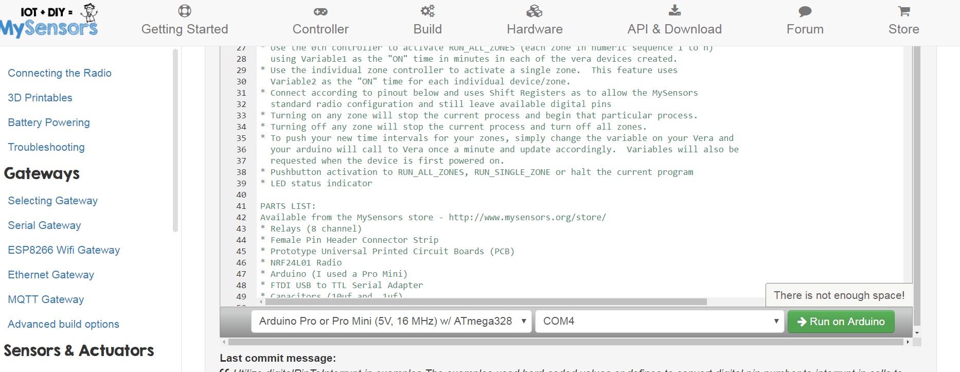
Hi Pete thank you very much, I am using mysensors online editor , not sure if I should edit that code?
-
It's not possible to disable this from codebender. You'll need to install the Arduino IDE onto your computer.
-
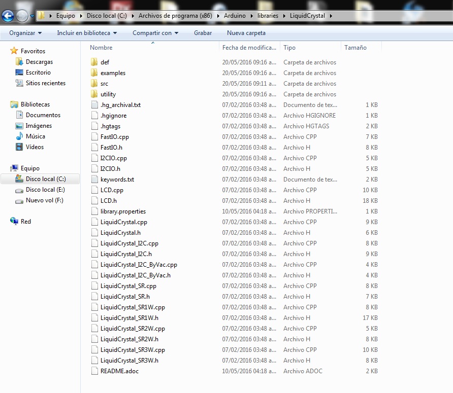
@hek in computer I get this:
C:\Program Files (x86)\Arduino\libraries\LiquidCrystal\I2CIO.cpp:35:26: fatal error: ../Wire/Wire.h: No such file or directory#include <../Wire/Wire.h>
^
compilation terminated.
exit status 1
Error compilación en tarjeta Arduino Pro or Pro Mini.
-
@David-Mora Maybe this will help:
https://www.youtube.com/watch?v=qUey_X9n2KI
-
thank you for your help ! I just reinstaled arduino and now I getthis ( I just downloaded the I.5 and copy and paste all libraries in the libraries folder:
TENCIÓN: Categoría '' en librería UIPEthernet no es válida. Configurando a 'Uncategorized'
C:\Users\David\Desktop\IrrigationController\IrrigationController.ino:92:31: fatal error: LiquidCrystal_I2C.h: No such file or directory#include <LiquidCrystal_I2C.h>
^
compilation terminated.
exit status 1
Error compilación en tarjeta Arduino Pro or Pro Mini.
-
@David-Mora quite sad I´ve spent two days now installing and uninstalling arduino and libraries and no luck
-
@David-Mora Did you close all instances of Arduino and open again after you added the LiquidCrystal library? It looks like it can't find it.
-
@petewill Yes Pete it doesnt work at all
-
@David-Mora hope this is the right way to post the code finally the only mistake is
Arduino:1.6.9 (Windows 7), Tarjeta:"Arduino Pro or Pro Mini, ATmega328 (5V, 16 MHz)"El Sketch usa 30,808 bytes (100%) del espacio de almacenamiento de programa. El máximo es 30,720 bytes.
Las variables Globales usan 1,329 bytes (64%) de la memoria dinámica, dejando 719 bytes para las variables locales. El máximo es 2,048 bytes.
processing.app.debug.RunnerException: Programa muy grando: visite http://www.arduino.cc/en/Guide/Troubleshooting#size para ver cómo reducirlo.
at cc.arduino.Compiler.size(Compiler.java:315)
at cc.arduino.Compiler.build(Compiler.java:156)
at processing.app.Sketch.build(Sketch.java:1111)
at processing.app.Sketch.build(Sketch.java:1081)
at processing.app.Editor$BuildHandler.run(Editor.java:1988)
at java.lang.Thread.run(Thread.java:745)
Programa muy grando: visite http://www.arduino.cc/en/Guide/Troubleshooting#size para ver cómo reducirlo.
Tarjeta en COM4 no disponibleEste reporte podría tener más información con
"Mostrar salida detallada durante la compilación"
opción habilitada en Archivo -> Preferencias.
-
@David-Mora Looks like you are almost there!
Did you disable debug? The sketch looks too big. To disable go to the MySensors library and open the MyConfig.h file in Notepad and change this line:
#define DEBUG
to
//#define DEBUG
Also, it looks like the Arduino IDE programmer isn't finding your Pro Mini. Did you select the correct Board and Port from the Tools menu? I don't have an Arduino next to me so my port isn't available to select but it should look similar to this (except you would choose your Port the Arduino is connected to):
-
On my controller i use diffren LCD library and i was commented out this line
//#include <LiquidCrystal_I2C.h> and //LiquidCrystal_I2C lcd(0x27, 2, 1, 0, 4, 5, 6, 7, 3, POSITIVE); // Set the LCD I2C address to 0x27
Sketch uses 27,916 bytes (90%) of program storage space. Maximum is 30,720 bytes.
Global variables use 1,295 bytes (63%) of dynamic memory, leaving 753 bytes for local variables. Maximum is 2,048 bytes.
-
Is there a way to use domoticz to connect with it and on/off this irrigation system? How to achive this?
My domoticz is running on raspberry pi 0.
-
Yes, i've had to manually set the valve runtimes on the ardunio code, because its not possible to pass the runtime variable etc, this is from the one i''ve got built. runtime is 1min, but you can edit as required.
else if (message.type == V_VAR1) { int variable1 = 60000; // atoi(message.data);// RUN_ALL_ZONES time DEBUG_PRINT(F("Recieved variable1 valve:")); DEBUG_PRINT(i); DEBUG_PRINT(F(" = ")); DEBUG_PRINTLN(variable1); if (variable1 != allZoneTime[i]) { allZoneTime[i] = variable1; zoneTimeUpdate = true; } } else if (message.type == V_VAR2) { int variable2 = 60000; //atoi(message.data);// RUN_SINGLE_ZONE time DEBUG_PRINT(F("Recieved variable2 valve:")); DEBUG_PRINT(i); DEBUG_PRINT(F(" = ")); DEBUG_PRINTLN(variable2); if (variable2 != valveSoloTime[i]) { valveSoloTime[i] = variable2; zoneTimeUpdate = true; } }
-
Thanks for posting, Mark. I was getting nuts figuring out what was the problem with my controller that was only activating 1sec each phase. I didn't implement it because that problem.
-
@Sergio-Rius no problem, i had plenty of issues trying to get this to work with openhab before i changed controller
-
So I have been thinking of building one of these. I have just ordered an 8 channel relay board from ebay. http://www.ebay.com/itm/5V-8-Channel-Relay-Board-Module-for-Arduino-Raspberry-Pi-ARM-AVR-DSP-PIC-MUC-/262472832393?hash=item3d1c999589:g:sDEAAOSwnFZXVj2p . I have been trying to sift through this thread and am not seeing what I am looking for. Does this project take into account a pump start relay? If not, I am wondering the best way to handle this. I only have 4 zones in my irrigation setup, so I could certainly use one of the relay channels for that if it is written into the sketch. One thought I had to save extra processing on the sketch in dealing with the shift register would be to put a diode on each output that would funnel to a single point, so whenever any relay is turned on the pump start connection point would go active. I would assume that something has already been calculated in for this, but I din't see anything.
Thanks for the great project. The Youtube video for this is actually what got me started with MySensors in the first place.
-
I'm going down the diodes route... another channel to trigger it is tricky to deal with unless you use normally off relays and use the code earlier in this thread. I tried to use it but use normally on relays so going for diodes.
K.I.S.S - keep it simple stupid no point making it harder for you if you have a workaround on the table
-
@Mark Jefford I can go that route, I just didn't know if someone already had that factored in to the project already. After thinking about it since I posted this, I could also go the route of using another single digital channel and wire it to one of the relays. Going that route would give me a couple things:
- One I could turn on the pump independent of a zone because I have a faucet connected to the setup that I can use. Currently I have to turn on a zone to use the faucet.
- Two, I could poll the state of the pump by checking the state of the one channel.
-
@Mark-Jefford I have the same issue. My system can't pass verifications for clock and valve data when I first plugged in because I don't know how to use this programs (Openhab, domoticz, etc.). Thank you!
-
Is it anybody who has this skecht in 24 hour format, instead of AM, PM?
-
@Lars65 Take a look at lines 663-667. I haven't tested this but it should be something similar to this:
lcd.print(hour() < 10 ? F(" ") : F("")); lcd.print(hour()); lcd.print(minute() < 10 ? F(":0") : F(":")); lcd.print(minute()); //lcd.print(isAM() ? F("am") : F("pm"));
-
Does anyone already made a pcb for this? My board keeps loosing it's "bridging" wires. They rot and fall near the solder.
-
@petewill I did try this, and it worked just fine. Thank you!
-
@Sergio-Rius Where do you have your controller located? I have had mine running for over a year now and haven't had any issues. Maybe you need to put it into a waterproof case?
To answer your question though, no, I don't believe anyone has created a PCB for this.
-
I will have mine in the greenhouse. Boxes is made of waxed oak,and it will be 3 modules, each one seald with a sillicone gasket.
I have some trash wood in the garage, so I thought I could use it to something.
-
Have anyone compiled it with the 2.0.0?
-
Hello Gentlemen, new to this board as well as new to micro electrics. Started this Irrigation Controller about a two weeks ago, after finding Pete B’s U tube video on this project. Got all the parts and have started building by following Pete B’s video. Have a few part questions and am not very literal with the nomenclature.
- This 4.7uF 50V 20% Axial-Lead Electrolytic Capacitor goes on which end or pins on the
- Have a FT232RL FTDI USB 3.3V 5.5V to TTL Serial Adapter Module for Mini Port that is different than Pete’s.
Not sure how to post JPEG's so this is the problem I am having.
0_1468546122072_7-14-16 Hello Gentlemen help.docx
The Pins on the ftdi are different than on Pete’s board, in that I cannot find the info for the double GND on the Arduino Pro Mini.
Any guidance of will be appreciated.
Respectfully RJ Myers
-
@Lars65 No, not yet. It's on the list but it will probably be a little while before I get to it.
@Ngwpower To add pictures you just have to drag and drop into the edit window. They will automatically upload.
-
Can you provide more info here? I'm not sure what you're asking.
-
Both of my FTDI adapters connect into the Pro Mini straight across (the wires don't get crossed when connecting. The key thing is TX on one side should go to RX on the other (and vice versa) then the other 4 wires line up from there. So, you almost have it correct in your picture but the TX and RX are switched. Just start from the DTR and go straight across.
-
-
Thank You, petewill I adjusted the wiring!
This is the picture for the 4.7 UF that has me baffled of where to insert into the radio. Being color blind really hurts with wiring. And rather ask than fry another project....
RJ
-
@Ngwpower
EDIT: My condenser is 10uF / 63v
-
Does this sketch still work with the current Mysensors libraries?
I lost my working environment so I had to build a new one. I downloaded the MySensors libraries and the sketch throws me an error not finding MySensor.h. The file is not at the libraries folder, but MySensorS.h
If adding this later (used at the samples) the compilation throws an error:W:\....\MySensors_Arduino\arduino-1.6.9\portable\sketchbook\libraries\MySensors/MySensors.h:287:4: error: #error No forward link or gateway feature activated. This means nowhere to send messages! Pretty pointless. #error No forward link or gateway feature activated. This means nowhere to send messages! Pretty pointless. ^ exit status 1 Error compilación en tarjeta Arduino Nano.``` Does make sense for anyone?
-
@Sergio-Rius
Than You for the clarfication & picture worth thousands of words.
RJ
-
@Sergio-Rius Hmm. Are you using the 2.0 release? If so then it's not compatible yet. It still needs to be upgraded.
-
Got the controller all ready to test like petewill shows in his presentation. Get this error
MySensors-1.5.4 loaded it onto my board Arduino Pro Mini and get this error -*** F:\Arduino Programs\My sensors downloads\upload-9cc672c5-a5a3-4711-9e38-8f3f7da898a5\upload-9cc672c5-a5a3-4711-9e38-8f3f7da898a5.ino:33:19: fatal error: Relay.h: No such file or directory***
Can I see this operate on my screen, without all the advanced technology? Found the Domoticz site and no sure if this is for me anymore than the Vera that is being used by petewill. Way out of my knowledge base with this project, just to stubborn to quit or give up.
-
@Ngwpower which sketch are you using?
-
@Lars65 Thanks
June 2, 2014 12:00 Version 1.0 Arduino Multi-Zone Sprinkler Control
-
@Ngwpower I use this one which is earlier in this thread, an it works with my domoticz.
/* MySprinkler for MySensors Arduino Multi-Zone Sprinkler Control May 31, 2015 *** Version 2.0 *** Upgraded to http://MySensors.org version 1.4.1 *** Expanded for up to 16 Valves *** Setup for active low relay board or comment out #define ACTIVE_LOW to switch to active high *** Switch to bitshift method vs byte arrays *** Changed RUN_ALL_ZONES Vera device to 0 (was highest valve) *** Added optional LCD display featuring remaining time, date last ran & current time *** Features 'raindrop' and 'clock' icons which indicate sensor is updating valve data and clock respectively *** Added single pushbutton menu to manually select which program to run (All Zones or a Single Zone) *** Added option of naming your Zones programmatically or with Vera (V_VAR3 used to store names) Utilizing your Vera home automation controller and the MySensors.org gateway you can control up to a sixteen zone irrigation system with only three digital pins. This sketch will create NUMBER_OF_VALVES + 1 devices on your Vera controller This sketch features the following: * Allows you to cycle through All zones (RUN_ALL_ZONES) or individual zone (RUN_SINGLE_ZONE) control. * Use the 0th controller to activate RUN_ALL_ZONES (each zone in numeric sequence 1 to n) using Variable1 as the "ON" time in minutes in each of the vera devices created. * Use the individual zone controller to activate a single zone. This feature uses Variable2 as the "ON" time for each individual device/zone. * Connect according to pinout below and uses Shift Registers as to allow the MySensors standard radio configuration and still leave available digital pins * Turning on any zone will stop the current process and begin that particular process. * Turning off any zone will stop the current process and turn off all zones. * To push your new time intervals for your zones, simply change the variable on your Vera and your arduino will call to Vera once a minute and update accordingly. Variables will also be requested when the device is first powered on. * Pushbutton activation to RUN_ALL_ZONES, RUN_SINGLE_ZONE or halt the current program * LED status indicator PARTS LIST: Available from the MySensors store - http://www.mysensors.org/store/ * Relays (8 channel) * Female Pin Header Connector Strip * Prototype Universal Printed Circuit Boards (PCB) * NRF24L01 Radio * Arduino (I used a Pro Mini) * FTDI USB to TTL Serial Adapter * Capacitors (10uf and .1uf) * 3.3v voltage regulator * Resistors (270 & 10K) * Female Dupont Cables * 1602 LCD (with I2C Interface) * LED * Push button * Shift Register (SN74HC595) * 2 Pole 5mm Pitch PCB Mount Screw Terminal Block * 3 Pole 5mm Pitch PCB Mount Screw Terminal Block * 22-24 gauge wire or similar (I used Cat5/Cat6 cable) * 18 gauge wire (for relay) * Irrigation Power Supply (24-Volt/750 mA Transformer) INSTRUCTIONS: * A step-by-step setup video is available here: http://youtu.be/l4GPRTsuHkI * After assembling your arduino, radio, decoupling capacitors, shift register(s), status LED, pushbutton LCD (I2C connected to A4 and A5) and relays, and load the sketch. * Following the instructions at https://MySensors.org include the device to your MySensors Gateway. * Verify that each new device has a Variable1, Variable2 and Variable3. Populate data accordingly with whole minutes for the RUN_ALL_ZONES routine (Variable1) and the RUN_SINGLE_ZONE routines (Variable 2). The values entered for times may be zero and you may use the defaulet zone names by leaving Variable3 blank. * Once you have entered values for each zone and each variable, save the settings by pressing the red save button on your Vera. * Restart your arduino; verify the settings are loaded into your arduino with the serial monitor; the array will be printed on the serial monitor. * Your arduino should slow-flash, indicating that it is in ready mode. * There are multiple debug serial prints that can be monitored to assure that it is operating properly. * ***THIS SHOULD NO LONGER BE NEEDED*** The standard MySensors library now works. https://bitbucket.org/fmalpartida/new-liquidcrystal/downloads for the I2C library, or use yours Contributed by Jim (BulldogLowell@gmail.com) with much contribution from Pete (pete.will@mysensors.org) and is released to the public domain */ // #include <Wire.h> #include <Time.h> #include <MySensor.h> #include <SPI.h> #include <LiquidCrystal.h> #include <LiquidCrystal_I2C.h> // #define NUMBER_OF_VALVES 4 // Change this to set your valve count up to 16. #define VALVE_RESET_TIME 7500UL // Change this (in milliseconds) for the time you need your valves to hydraulically reset and change state #define RADIO_ID AUTO // Change this to fix your Radio ID or use Auto #define SKETCH_NAME "MySprinkler Domoticz" #define SKETCH_VERSION "2.0" // #define CHILD_ID_SPRINKLER 0 // //#define ACTIVE_LOW // comment out this line if your relays are active high // #define DEBUG_ON // comment out to supress serial monitor output // #ifdef ACTIVE_LOW #define BITSHIFT_VALVE_NUMBER ~(1U << (valveNumber-1)) #define ALL_VALVES_OFF 0xFFFF #else #define BITSHIFT_VALVE_NUMBER (1U << (valveNumber-1)) #define ALL_VALVES_OFF 0U #endif // #ifdef DEBUG_ON #define DEBUG_PRINT(x) Serial.print(x) #define DEBUG_PRINTLN(x) Serial.println(x) #define SERIAL_START(x) Serial.begin(x) #else #define DEBUG_PRINT(x) #define DEBUG_PRINTLN(x) #define SERIAL_START(x) #endif // typedef enum { STAND_BY_ALL_OFF, RUN_SINGLE_ZONE, RUN_ALL_ZONES, CYCLE_COMPLETE, ZONE_SELECT_MENU } SprinklerStates; // SprinklerStates state = STAND_BY_ALL_OFF; SprinklerStates lastState; byte menuState = 0; unsigned long menuTimer; byte countDownTime = 10; // int allZoneTime [NUMBER_OF_VALVES + 1]= {0, 1, 1, 1, 1}; // Insert values in min, 0 = all zone (always 0) this is a 4 chan relay int valveSoloTime [NUMBER_OF_VALVES + 1]= {0, 1, 1, 1, 1}; // Insert values in min, 0 = all zone (always 0) this is a 4 chan relay int valveNumber; int lastValve; unsigned long startMillis; const int ledPin = 5; const int waterButtonPin = 3; boolean buttonPushed = false; boolean showTime = true; boolean clockUpdating = false; boolean recentUpdate = true; const char *dayOfWeek[] = { "Null", "Sunday ", "Monday ", "Tuesday ", "Wednesday ", "Thursday ", "Friday ", "Saturday " }; // Name your Zones here or use Vera to edit them by adding a name in Variable3... String valveNickName[17] = { "All Zones", "Zone 1", "Zone 2", "Zone 3", "Zone 4", "Zone 5", "Zone 6", "Zone 7", "Zone 8", "Zone 9", "Zone 10", "Zone 11", "Zone 12", "Zone 13", "Zone 14", "Zone 15", "Zone 16" }; // time_t lastTimeRun = 0; //Setup Shift Register... const int latchPin = 8; const int clockPin = 4; const int dataPin = 7; // byte clock[8] = {0x0, 0xe, 0x15, 0x17, 0x11, 0xe, 0x0}; // fetching time indicator byte raindrop[8] = {0x4, 0x4, 0xA, 0xA, 0x11, 0xE, 0x0,}; // fetching Valve Data indicator // Set the pins on the I2C chip used for LCD connections: // addr, en,rw,rs,d4,d5,d6,d7,bl,blpol LiquidCrystal_I2C lcd(0x27, 2, 1, 0, 4, 5, 6, 7, 3, POSITIVE); // Set the LCD I2C address to 0x27 MySensor gw; // MyMessage msg1valve(CHILD_ID_SPRINKLER, V_LIGHT); MyMessage var1valve(CHILD_ID_SPRINKLER, V_VAR1); MyMessage var2valve(CHILD_ID_SPRINKLER, V_VAR2); // void setup() { SERIAL_START(115200); DEBUG_PRINTLN(F("Initialising...")); pinMode(latchPin, OUTPUT); pinMode(clockPin, OUTPUT); pinMode(dataPin, OUTPUT); pinMode(ledPin, OUTPUT); pinMode(waterButtonPin, INPUT_PULLUP); //pinMode(waterButtonPin, INPUT); attachInterrupt(1, PushButton, RISING); //May need to change for your Arduino model digitalWrite (ledPin, HIGH); DEBUG_PRINTLN(F("Turning All Valves Off...")); updateRelays(ALL_VALVES_OFF); //delay(5000); lcd.begin(16, 2); //(16 characters and 2 line display) lcd.clear(); lcd.backlight(); lcd.createChar(0, clock); lcd.createChar(1, raindrop); // //check for saved date in EEPROM DEBUG_PRINTLN(F("Checking EEPROM for stored date:")); delay(500); if (gw.loadState(0) == 0xFF); // EEPROM flag { DEBUG_PRINTLN(F("Retreiving last run time from EEPROM...")); for (int i = 0; i < 4 ; i++) { lastTimeRun = lastTimeRun << 8; lastTimeRun = lastTimeRun | gw.loadState(i + 1); // assemble 4 bytes into an ussigned long epoch timestamp } } gw.begin(getVariables, RADIO_ID, false); // Change 'false' to 'true' to create a Radio repeating node gw.sendSketchInfo(SKETCH_NAME, SKETCH_VERSION); for (byte i = 0; i <= NUMBER_OF_VALVES; i++) { gw.present(i, S_LIGHT); } DEBUG_PRINTLN(F("Sensor Presentation Complete")); // digitalWrite (ledPin, LOW); DEBUG_PRINTLN(F("Ready...")); // lcd.setCursor(0, 0); lcd.print(F(" Syncing Time ")); lcd.setCursor(15, 0); lcd.write(byte(0)); lcd.setCursor(0, 1); int clockCounter = 0; while (timeStatus() == timeNotSet && clockCounter < 21) { gw.process(); gw.requestTime(receiveTime); DEBUG_PRINTLN(F("Requesting time from Gateway:")); delay(1000); lcd.print("."); clockCounter++; if (clockCounter > 16) { DEBUG_PRINTLN(F("Failed initial clock synchronization!")); lcd.clear(); lcd.print(F(" Failed Clock ")); lcd.setCursor(0, 1); lcd.print(F(" Syncronization ")); delay(2000); break; } } // lcd.clear(); /* //Update valve data when first powered on for (byte i = 0; i <= NUMBER_OF_VALVES; i++) { lcd.print(F(" Updating ")); lcd.setCursor(0, 1); lcd.print(F(" Valve Data: ")); lcd.print(i); boolean flashIcon = false; DEBUG_PRINT(F("Calling for Valve ")); DEBUG_PRINT(i); DEBUG_PRINTLN(F(" Data...")); while (gw.process() == false) { lcd.setCursor(15, 0); flashIcon = !flashIcon; flashIcon ? lcd.write(byte(1)) : lcd.print(F(" ")); gw.request(i, V_VAR1); delay(100); } while (gw.process() == false) { lcd.setCursor(15, 0); flashIcon = !flashIcon; flashIcon ? lcd.write(byte(1)) : lcd.print(F(" ")); gw.request(i, V_VAR2); delay(100); } while (gw.process() == false) { lcd.setCursor(15, 0); flashIcon = !flashIcon; flashIcon ? lcd.write(byte(1)) : lcd.print(F(" ")); gw.request(i, V_VAR3); delay(100); } } */ lcd.clear(); } // void loop() { gw.process(); updateClock(); updateDisplay(); //goGetValveTimes(); // if (buttonPushed) { menuTimer = millis(); DEBUG_PRINTLN(F("Button Pressed")); if (state == STAND_BY_ALL_OFF) { state = ZONE_SELECT_MENU; menuState = 0; } else if (state == ZONE_SELECT_MENU) { menuState++; if (menuState > NUMBER_OF_VALVES) { menuState = 0; } } else { state = STAND_BY_ALL_OFF; } buttonPushed = false; } if (state == STAND_BY_ALL_OFF) { slowToggleLED (); if (state != lastState) { updateRelays(ALL_VALVES_OFF); DEBUG_PRINTLN(F("State Changed... all Zones off")); for (byte i = 0; i <= NUMBER_OF_VALVES; i++) { delay(50); gw.send(msg1valve.setSensor(i).set(false), false); } lcd.clear(); lcd.setCursor(0,0); lcd.print(F("** Irrigation **")); lcd.setCursor(0,1); lcd.print(F("** Halted **")); delay(2000); lastValve = -1; } } // else if (state == RUN_ALL_ZONES) { if (lastValve != valveNumber) { for (byte i = 0; i <= NUMBER_OF_VALVES; i++) { if (i == 0 || i == valveNumber) { gw.send(msg1valve.setSensor(i).set(true), false); } else { gw.send(msg1valve.setSensor(i).set(false), false); } } } lastValve = valveNumber; fastToggleLed(); if (state != lastState) { valveNumber = 1; updateRelays(ALL_VALVES_OFF); DEBUG_PRINTLN(F("State Changed, Running All Zones...")); } unsigned long nowMillis = millis(); if (nowMillis - startMillis < VALVE_RESET_TIME) { updateRelays(ALL_VALVES_OFF); } else if (nowMillis - startMillis < (allZoneTime[valveNumber] * 60000UL)) { updateRelays(BITSHIFT_VALVE_NUMBER); } else { DEBUG_PRINTLN(F("Changing Valves...")); updateRelays(ALL_VALVES_OFF); startMillis = millis(); valveNumber++; if (valveNumber > NUMBER_OF_VALVES) { state = CYCLE_COMPLETE; startMillis = millis(); lastValve = -1; lastTimeRun = now(); saveDateToEEPROM(lastTimeRun); for (byte i = 0; i <= NUMBER_OF_VALVES; i++) { gw.send(msg1valve.setSensor(i).set(false), false); } DEBUG_PRINT(F("State = ")); DEBUG_PRINTLN(state); } } } // else if (state == RUN_SINGLE_ZONE) { fastToggleLed(); if (state != lastState) { for (byte i = 0; i <= NUMBER_OF_VALVES; i++) { if (i == 0 || i == valveNumber) { gw.send(msg1valve.setSensor(i).set(true), false); } else { gw.send(msg1valve.setSensor(i).set(false), false); } } DEBUG_PRINTLN(F("State Changed, Single Zone Running...")); DEBUG_PRINT(F("Zone: ")); DEBUG_PRINTLN(valveNumber); } unsigned long nowMillis = millis(); if (nowMillis - startMillis < VALVE_RESET_TIME) { updateRelays(ALL_VALVES_OFF); } else if (nowMillis - startMillis < (valveSoloTime [valveNumber] * 60000UL)) { updateRelays(BITSHIFT_VALVE_NUMBER); } else { updateRelays(ALL_VALVES_OFF); for (byte i = 0; i <= NUMBER_OF_VALVES; i++) { gw.send(msg1valve.setSensor(i).set(false), false); } state = CYCLE_COMPLETE; startMillis = millis(); DEBUG_PRINT(F("State = ")); DEBUG_PRINTLN(state); } lastTimeRun = now(); } else if (state == CYCLE_COMPLETE) { if (millis() - startMillis < 30000UL) { fastToggleLed(); } else { state = STAND_BY_ALL_OFF; } } else if (state = ZONE_SELECT_MENU) { displayMenu(); } lastState = state; } // void displayMenu(void) { static byte lastMenuState = -1; static int lastSecond; if (menuState != lastMenuState) { lcd.clear(); lcd.setCursor(0, 0); lcd.print(valveNickName[menuState]); lcd.setCursor(0, 1); lcd.print(F("Starting")); DEBUG_PRINT(valveNickName[menuState]); Serial.print(F(" Starting Shortly")); } int thisSecond = (millis() - menuTimer) / 1000UL; if (thisSecond != lastSecond && thisSecond < 8) { lcd.print(F(".")); Serial.print("."); } lastSecond = thisSecond; if (millis() - menuTimer > 10000UL) { startMillis = millis(); if (menuState == 0) { valveNumber = 1; state = RUN_ALL_ZONES; } else { valveNumber = menuState; state = RUN_SINGLE_ZONE; } } else { } lastMenuState = menuState; } // void updateRelays(int value) { digitalWrite(latchPin, LOW); shiftOut(dataPin, clockPin, MSBFIRST, highByte(value)); shiftOut(dataPin, clockPin, MSBFIRST, lowByte(value)); digitalWrite(latchPin, HIGH); } // void PushButton() //interrupt with debounce { static unsigned long last_interrupt_time = 0; unsigned long interrupt_time = millis(); if (interrupt_time - last_interrupt_time > 200) { buttonPushed = true; } last_interrupt_time = interrupt_time; } // void fastToggleLed() { static unsigned long fastLedTimer; if (millis() - fastLedTimer >= 100UL) { digitalWrite(ledPin, !digitalRead(ledPin)); fastLedTimer = millis (); } } // void slowToggleLED () { static unsigned long slowLedTimer; if (millis() - slowLedTimer >= 1250UL) { digitalWrite(ledPin, !digitalRead(ledPin)); slowLedTimer = millis (); } } // void getVariables(const MyMessage &message) { boolean zoneTimeUpdate = false; if (message.isAck()) { DEBUG_PRINTLN(F("This is an ack from gateway")); } for (byte i = 0; i <= NUMBER_OF_VALVES; i++) { if (message.sensor == i) { if (message.type == V_LIGHT) { int switchState = atoi(message.data); if (switchState == 0) { state = STAND_BY_ALL_OFF; DEBUG_PRINTLN(F("Recieved Instruction to Cancel...")); } else { if (i == 0) { state = RUN_ALL_ZONES; valveNumber = 1; DEBUG_PRINTLN(F("Recieved Instruction to Run All Zones...")); } else { state = RUN_SINGLE_ZONE; valveNumber = i; DEBUG_PRINT(F("Recieved Instruction to Activate Zone: ")); DEBUG_PRINTLN(i); } } startMillis = millis(); } else if (message.type == V_VAR1) { int variable1 = atoi(message.data);// RUN_ALL_ZONES time DEBUG_PRINT(F("Recieved variable1 valve:")); DEBUG_PRINT(i); DEBUG_PRINT(F(" = ")); DEBUG_PRINTLN(variable1); if (variable1 != allZoneTime[i]) { allZoneTime[i] = variable1; zoneTimeUpdate = true; } } else if (message.type == V_VAR2) { int variable2 = atoi(message.data);// RUN_SINGLE_ZONE time DEBUG_PRINT(F("Recieved variable2 valve:")); DEBUG_PRINT(i); DEBUG_PRINT(F(" = ")); DEBUG_PRINTLN(variable2); if (variable2 != valveSoloTime[i]) { valveSoloTime[i] = variable2; zoneTimeUpdate = true; } } else if (message.type == V_VAR3) { String newMessage = String(message.data); if (newMessage.length() == 0) { DEBUG_PRINT(F("No Name Recieved for zone ")); DEBUG_PRINTLN(i); break; } if (newMessage.length() > 16) { newMessage.substring(0, 16); } valveNickName[i] = ""; valveNickName[i] += newMessage; DEBUG_PRINT(F("Recieved new name for zone ")); DEBUG_PRINT(i); DEBUG_PRINT(F(" and it is now called: ")); DEBUG_PRINTLN(valveNickName[i]); } } } if (zoneTimeUpdate) { // DEBUG_PRINTLN(F("New Zone Times Recieved...")); for (byte i = 0; i <= NUMBER_OF_VALVES; i++) { if (i != 0) { DEBUG_PRINT(F("Zone ")); DEBUG_PRINT(i); DEBUG_PRINT(F(" individual time: ")); DEBUG_PRINT(valveSoloTime[i]); DEBUG_PRINT(F(" group time: ")); DEBUG_PRINTLN(allZoneTime[i]); recentUpdate = true; } } } else { recentUpdate = false; } } // void updateDisplay() { static unsigned long lastUpdateTime; static boolean displayToggle = false; //static byte toggleCounter = 0; static SprinklerStates lastDisplayState; if (state != lastDisplayState || millis() - lastUpdateTime >= 3000UL) { displayToggle = !displayToggle; switch (state) { case STAND_BY_ALL_OFF: // fastClear(); lcd.setCursor(0, 0); if (displayToggle) { lcd.print(F(" System Ready ")); if (clockUpdating) { lcd.setCursor(15, 0); lcd.write(byte(0)); } lcd.setCursor(0, 1); lcd.print(hourFormat12() < 10 ? F(" ") : F("")); lcd.print(hourFormat12()); lcd.print(minute() < 10 ? F(":0") : F(":")); lcd.print(minute()); lcd.print(isAM() ? F("am") : F("pm")); lcd.print(month() < 10 ? F(" 0") : F(" ")); lcd.print(month()); lcd.print(day() < 10 ? F("/0") : F("/")); lcd.print(day()); lcd.print(F("/")); lcd.print(year() % 100); } else { lcd.print(F(" Last Watered ")); if (clockUpdating) { lcd.setCursor(15, 0); lcd.write(byte(0)); } lcd.setCursor(0, 1); lcd.print(dayOfWeek[weekday(lastTimeRun)]); lcd.setCursor(11, 1); lcd.print(month(lastTimeRun) < 10 ? F(" ") : F("")); lcd.print(month(lastTimeRun)); lcd.print(day(lastTimeRun) < 10 ? F("/0") : F("/")); lcd.print(day(lastTimeRun)); } break; case RUN_SINGLE_ZONE: // fastClear(); lcd.setCursor(0, 0); if (displayToggle) { lcd.print(F("Single Zone Mode")); lcd.setCursor(0, 1); lcd.print(F(" Zone:")); if (valveNumber < 10) lcd.print(F("0")); lcd.print(valveNumber); lcd.print(F(" Active")); } else { lcd.print(F(" Time Remaining ")); lcd.setCursor(0, 1); if (valveSoloTime[valveNumber] == 0) { lcd.print(F(" No Valve Time ")); } else { unsigned long timeRemaining = (valveSoloTime[valveNumber] * 60) - ((millis() - startMillis) / 1000); lcd.print(timeRemaining / 60 < 10 ? " 0" : " "); lcd.print(timeRemaining / 60); lcd.print("min"); lcd.print(timeRemaining % 60 < 10 ? " 0" : " "); lcd.print(timeRemaining % 60); lcd.print("sec "); } } break; case RUN_ALL_ZONES: // fastClear(); lcd.setCursor(0, 0); if (displayToggle) { lcd.print(F(" All-Zone Mode ")); lcd.setCursor(0, 1); lcd.print(F(" Zone:")); if (valveNumber < 10) lcd.print(F("0")); lcd.print(valveNumber); lcd.print(F(" Active ")); } else { lcd.print(F(" Time Remaining ")); lcd.setCursor(0, 1); int timeRemaining = (allZoneTime[valveNumber] * 60) - ((millis() - startMillis) / 1000); lcd.print((timeRemaining / 60) < 10 ? " 0" : " "); lcd.print(timeRemaining / 60); lcd.print("min"); lcd.print(timeRemaining % 60 < 10 ? " 0" : " "); lcd.print(timeRemaining % 60); lcd.print("sec "); } break; case CYCLE_COMPLETE: // if (displayToggle) { lcd.setCursor(0, 0); lcd.print(F(" Watering Cycle ")); lcd.setCursor(0, 1); lcd.print(F(" Complete ")); } else { int totalTimeRan = 0; for (int i = 1; i < NUMBER_OF_VALVES + 1; i++) { totalTimeRan += allZoneTime[i]; } lcd.setCursor(0, 0); lcd.print(F(" Total Time Run ")); lcd.setCursor(0, 1); lcd.print(totalTimeRan < 10 ? " 0" : " "); lcd.print(totalTimeRan); lcd.print(" Minutes "); } } lastUpdateTime = millis(); } lastDisplayState = state; } void receiveTime(time_t newTime) { DEBUG_PRINTLN(F("Time value received and updated...")); int lastSecond = second(); int lastMinute = minute(); int lastHour = hour(); setTime(newTime); if (((second() != lastSecond) || (minute() != lastMinute) || (hour() != lastHour)) || showTime) { DEBUG_PRINTLN(F("Clock updated....")); DEBUG_PRINT(F("Sensor's time currently set to:")); DEBUG_PRINT(hourFormat12() < 10 ? F(" 0") : F(" ")); DEBUG_PRINT(hourFormat12()); DEBUG_PRINT(minute() < 10 ? F(":0") : F(":")); DEBUG_PRINT(minute()); DEBUG_PRINTLN(isAM() ? F("am") : F("pm")); DEBUG_PRINT(month()); DEBUG_PRINT(F("/")); DEBUG_PRINT(day()); DEBUG_PRINT(F("/")); DEBUG_PRINTLN(year()); DEBUG_PRINTLN(dayOfWeek[weekday()]); showTime = false; } else { DEBUG_PRINTLN(F("Sensor's time did NOT need adjustment greater than 1 second.")); } clockUpdating = false; } void fastClear() { lcd.setCursor(0, 0); lcd.print(F(" ")); lcd.setCursor(0, 1); lcd.print(F(" ")); } // void updateClock() { static unsigned long lastVeraGetTime; if (millis() - lastVeraGetTime >= 3600000UL) // updates clock time and gets zone times from vera once every hour { DEBUG_PRINTLN(F("Requesting time and valve data from Gateway...")); lcd.setCursor(15, 0); lcd.write(byte(0)); clockUpdating = true; gw.requestTime(receiveTime); lastVeraGetTime = millis(); } } // void saveDateToEEPROM(unsigned long theDate) { DEBUG_PRINTLN(F("Saving Last Run date")); if (gw.loadState(0) != 0xFF) { gw.saveState(0, 0xFF); // EEPROM flag for last date saved stored in EEPROM (location zero) } // for (int i = 1; i < 5; i++) { gw.saveState(5 - i, byte(theDate >> 8 * (i - 1))); // store epoch datestamp in 4 bytes of EEPROM starting in location one } } // void goGetValveTimes() { static unsigned long valveUpdateTime; static byte valveIndex = 1; if (millis() - valveUpdateTime >= 300000UL / NUMBER_OF_VALVES)// update each valve once every 5 mins (distributes the traffic) { DEBUG_PRINTLN(F("Calling for Valve Data...")); lcd.setCursor(15, 0); lcd.write(byte(1)); //lcd.write(1); gw.request(valveIndex, V_VAR1); gw.request(valveIndex, V_VAR2); gw.request(valveIndex, V_VAR3); valveUpdateTime = millis(); valveIndex++; if (valveIndex > NUMBER_OF_VALVES + 1) { valveIndex = 1; } } }``` Take away the three dots in the bottom.
-
Does anyone have a working portable Arduino IDE for that sketch that would want to share with me? I lost my installation and so many things changed in the built in scripts when you do a new installation. I can compile the project even using 1.4.5 mysensors libraries.
Thanks a lot.
-
@Ngwpower Don't give up! It is a learning curve for sure but totally worth it when you finally get it. Try the irrigation controller sketch from the MySensors 1.5 library example. All the required stuff should be there.
@Sergio-Rius I'm not sure what you're looking for. Do you need the 1.5 version?
-
Thanks, I envy you young people at 67 just opening the wide world of tech - do't have to do this sitting on a motor grader or Bull Dozer in the high desert. I have tried from 1.3 to 2.0 and thought I saw a flicker of LED in the string of switches, as in your example. Had my 5V on the wrong pin, so back to square one.
I am having fun attempting to learn the terminology as well as the application!
-
@Ngwpower I am 55 and still learning. I don't know anything about programming. But I spend a lot of time on forums, and reading.
I would love to learn programming, but I have a slow learning curve now.
I work as a processengineer,so I guess I can understand some logic.
But this is really fun stuff.
Started up a couple of years ago, reading about a home made CNC mill.
Now I have my own, and it got pretty big can mill surfaces about 1100x800mm.
And I use it most to mill PCB boards. Hahaha.
-
@petewill
The problem are the new libraries that come with newer arduino ide. My attempts fail about the wire.h library location or a wrong "positive" variable at liquiddisplay.
I think it's not compatible with newer libraries.
-
@Ngwpower said:
I envy you young people at 67 just opening the wide world of tech
I was just thinking the other day I can't wait until I retire so I'll have more time to work on this stuff
I'm glad you're not giving up. It took me a while to get it too but eventually it all started to make a little sense. Unfortunately you're starting at a harder time because we are all still getting comfortable with 2.0@Sergio-Rius Ok, I haven't updated my libraries for a while so hopefully these will work for you. 0_1468884836658_Libraries.zip
-
@petewill
Thank you very much. Unfortunately those are not the libraries I've problems with. The problem are the built-in ones. The ones that come with the Arduino IDE.
What version of the IDE are you running? I guess you use the Mysensors 1.4.2 libs.I installed Arduino IDE 1.6.9 and using your libraries, those are the errors shown:
WARNING: Category '' in library UIPEthernet is not valid. Setting to 'Uncategorized' W:\Domotica\MySensors_Arduino\arduino-1.6.9\portable\sketchbook\libraries\LiquidCrystal\I2CIO.cpp:35:26: fatal error: ../Wire/Wire.h: No such file or directory #include <../Wire/Wire.h> ^ compilation terminated. Multiple libraries were found for "Wire.h" Used: W:\Domotica\MySensors_Arduino\arduino-1.6.9\portable\sketchbook\libraries\Wire Not used: W:\Domotica\MySensors_Arduino\arduino-1.6.9\hardware\arduino\avr\libraries\Wire Multiple libraries were found for "LiquidCrystal.h" Used: W:\Domotica\MySensors_Arduino\arduino-1.6.9\portable\sketchbook\libraries\LiquidCrystal Not used: W:\Domotica\MySensors_Arduino\arduino-1.6.9\libraries\LiquidCrystal exit status 1 Error compiling for board Arduino Nano.
As you can appreciate, the Wire library is at the ../Wire path, so that error is meaningless.
I told you that I hate java environments? I still haven't found one that works out of the developer computer without issues. X)EDIT: So the problem is that the Wire library has been updated, but we are still using an old version of the LiquidCrystal. This last one expects the .h files been on the root library folder but this has been changed in newer versions. Built-in libraries have their code in "src" subfolder.
I moved it to parent folder and it compiles, but I don't know what will happen with other dependencies.
Better would be updating the sketch.
-
@Lars65
As you also use it from Domoticz, your controller notices the changes in valves? I mean, when the IC is cycling through zones, Domoticz correctly changes states or you must refresh the page for it to show?
-
@Sergio-Rius yes, I can turn them on/off, and the switch is also shifting from on/off.
-
@Sergio-Rius Those can you download from internet. About Liquidcrystal is there a newer version called NewLiquidCrystal, that is also possible to download.
That one worked for me.
I deleted all my duplicates, it is anoying when you get those messeges in the arduino ide.
Also the fatal error you get is ../wire/wire.h.
seems like you have #include <../Wire/Wire.h
What happens if you just write #include Wire.hWhat happens if you just
Suggested Topics
-
Welcome
Announcements • • hek