Refrigeration Datta Logger (A Non MySensors Project)
-
So I've been wanting to build a Refrigeration Temp / Current logger for some time now, and I finally got around to it (spured by a post on another board). So while this is not a MySensors project, I thought it may help those who are thinking about doing something similar.
Just about all the information to build a temp / current logger is out there on the Internets so there's nothing terribly innovative about it.
Features:
- Logs the following to an Adafruit SD Card Shield
3 DHT's (Temperature and Humidity)
1 Equipment Current
2 Light levels - Uses a settings.ini file to choose logging options.
- Uses a fairly robust error function.
- 6.5 Second log rate (this is the fastest due to the DHT's)
- Can log data indefinitely (Limited only by the size SD Card).
- Core design can be used on both 125vac and 220vac equipment. (Internal Power Supply Allows for this)
BOM:
Core Items:
- UNO R3 ATmega328P
- Adafruit Assembled Data Logging shield for Arduino
- DHT22 AM2302 Digital Temperature and Humidity Sensor Module
- Non-invasive AC Sensor Split Core Current Transformer SCT-013-000 0-100A
- 1/4W Metal Film Resistors Assorted kit 75 Values
- Kit 10value 100pcs 4X7mm Electrolytic Capacitor Assortment
- 10PCS Double Side Prototype PCB Tinned Universal Breadboard
- 20pcs, PushButton SPST Momentary Normal OFF N/O Push Switch Red Cap Push to Make
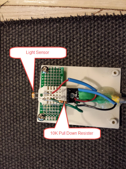
- 20PCS Photo Light Sensitive Resistor Photoresistor Optoresistor 5mm GL5539
- Some type of case. I used a old Grasslin DTMV40-M Multi Voltage Defrost Timer case since we use them at work, but you can use any appropriately sized case.
- Plastic Project Box Electronic Junction Case
- Extension Cord
- Romex Connectors
- CONTROL WIRE 26AWG. 4 CONDUCTORS. This is VERY important and I wound up going through several different wire types and sizes. You must not use anything larger then 26AWG, and It must be stranded. 26AWG stranded telephone cable should work very well, because it's somewhat flat and will help when passing it through the refrigerator door seals.
- If not building your own.This Power Supply @ 9v should work
Optionals:
3) 10pcs PCB Panel Mount 4 Pins 3.5mm Female Socket Stereo Headphone Jack
3) 10 PCS 4-pole 3.5mm Stereo MIC Audio Male Female Plug Jack SolderingIf you build you own power supply:
- 20 Pieces ELECTROLYTIC CAPACITORS 4.7uf 400v
- Transformer
- Fuse (1A)
- MOV (471KD05)
- Tvs
BUILDING IT UP:
Contributing Web Sites
https://learn.adafruit.com/adafruit-data-logger-shield
http://www.homautomation.org/2013/09/17/current-monitoring-with-non-invasive-sensor-and-arduino/
You can build it up on a bread board if you like, but I'm just going to start off with my actual build.
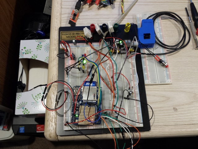
Here's my breadboard mess.
PSU:
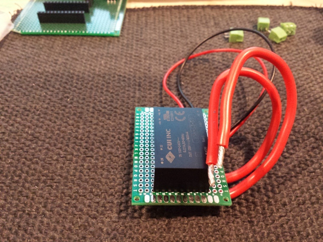
I choose to build my own power supply, but you can simply use a 'wall wart'
Here is the base PSU, without the caps, MOV and Tvs (I forgot to take pics of the final)
Distribution Board:
The distribution board handles the current sensing, LED and Power circuits.
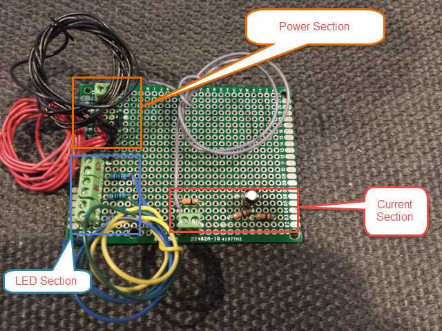
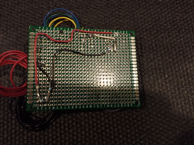
Here is the diagram for the Current Sensing circuit section:

Here is a diagram for the LED's circuit section:
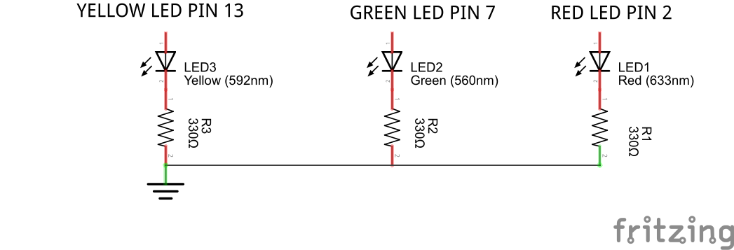
Sensor Connect Board:
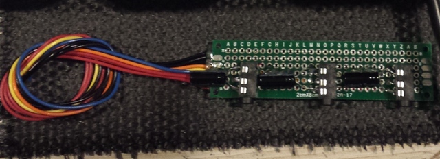
This is an option section, (You can hard wire the sensors but you will need to create a connection break of some type so you can pass the wire through the refrigerator door gasket)
Here is a picture of the board.
Assembly:
Case with PSU Install
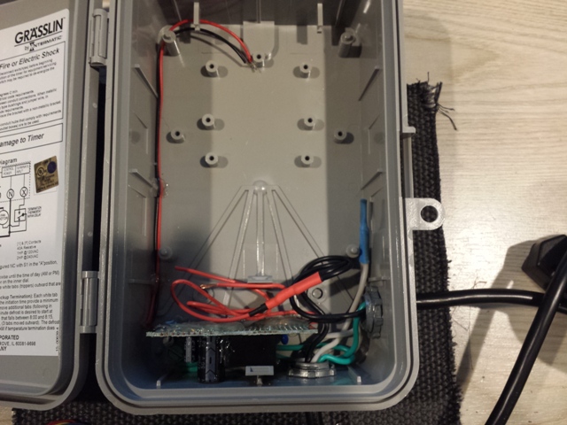
Case with Sensor Connect Board Installed
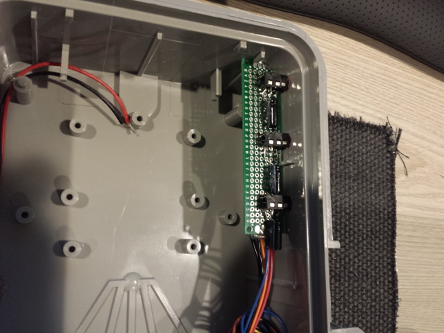
First attempt with drilling the holes.
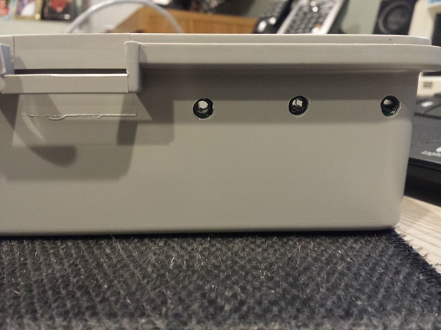
Second attempt, unfortunately after the board was glued in place. But with a conical grinder and a Dremel it worked perfectly
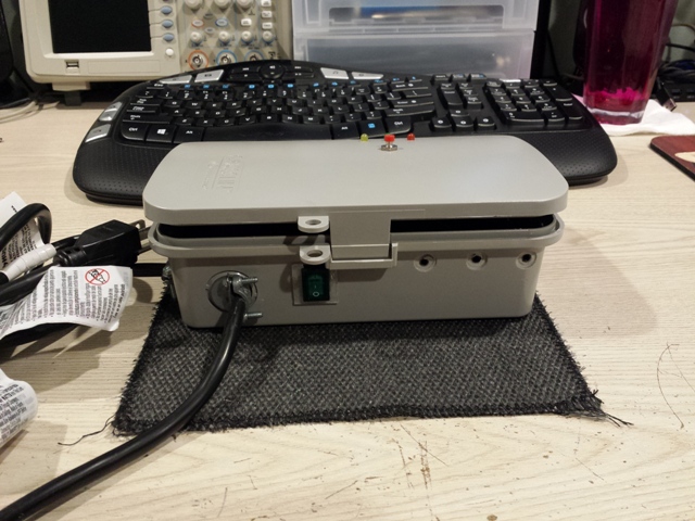
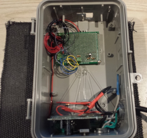
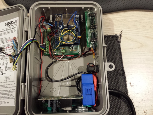
Case with Distribution Board
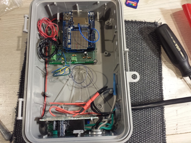
Case with Arduino and Logging Shield Installed
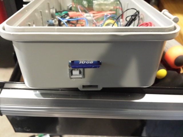
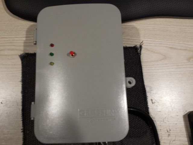
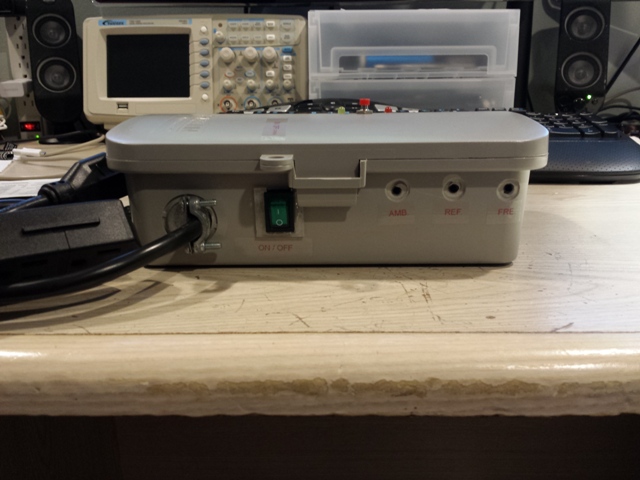
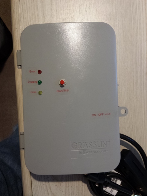
Case with CT, ON/OFF switch, Start Switch and LED's
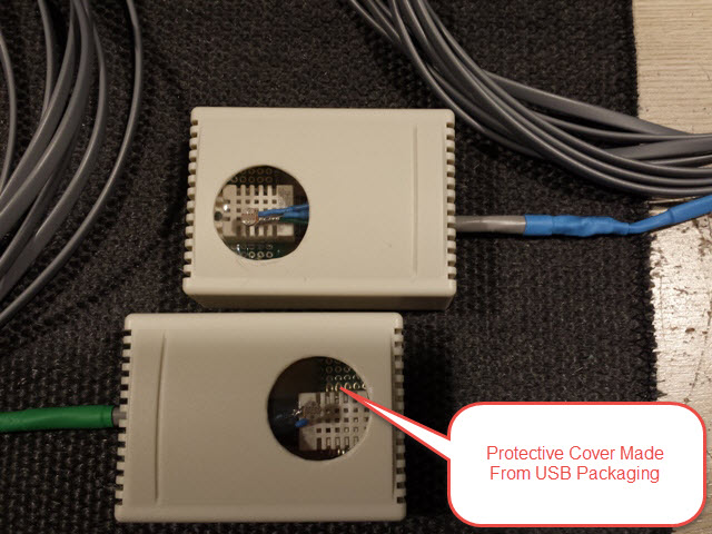
Sensors:
Testing:
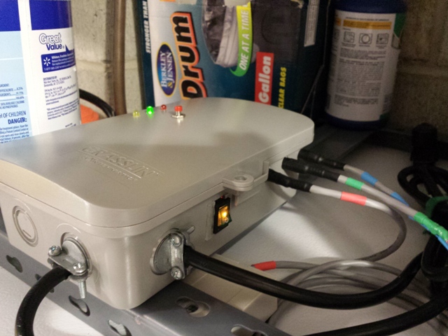
Case with some outfitted with some 'Bling'
Hopefully I didn't miss anything...
Next Up.... High Temp (Oven) logger..... Well maybe next up, maybe not... ;-)
- Logs the following to an Adafruit SD Card Shield
-
Here is the file deposit
https://github.com/ServiceXp/RefrigerationDataLogger
It uses the latest DHT22 libraries and a modified version of Steve Marple's IniFile libraries
Here is the sketch:
https://codebender.cc/sketch:60303 -
Great initiative! I've always wanted to do something similar (with MySensors preferably) but I've always stumbled on the mechanical issues, like getting the wire inside the cabinets. Especially in freezers letting even a little damp/hot air in would create icing. But AWG26 may be thin enough to get around this? Thought about drilling through the cabinets, but I'd really have to have a schematic so I'd not hit anything vital. Another option would be to run a cable where each of the thermostats are, but you'd have to temporarily remove the thermostat wire and that just seems like and awful lot of work if you need to do four times or so (when you have two freezers / fridges that are split 50/50).
-
Great initiative! I've always wanted to do something similar (with MySensors preferably) but I've always stumbled on the mechanical issues, like getting the wire inside the cabinets. Especially in freezers letting even a little damp/hot air in would create icing. But AWG26 may be thin enough to get around this? Thought about drilling through the cabinets, but I'd really have to have a schematic so I'd not hit anything vital. Another option would be to run a cable where each of the thermostats are, but you'd have to temporarily remove the thermostat wire and that just seems like and awful lot of work if you need to do four times or so (when you have two freezers / fridges that are split 50/50).
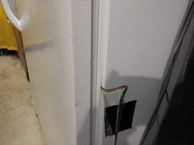
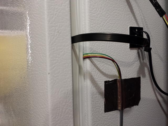
Thanks @bjornhallberg, In my testing on my freezer, I found, through a bit of trial an error, that stranded 26awg wire with the outer jacket removed gave me very good results. I ran the logger for 3 days with no noticeable problem.
Keep in mind this logger will be used by us as a diagnostic tool, (I work for an HA HVAC/R company) so it's use is temporary. If you are interested in a permanent solution look at these pics:
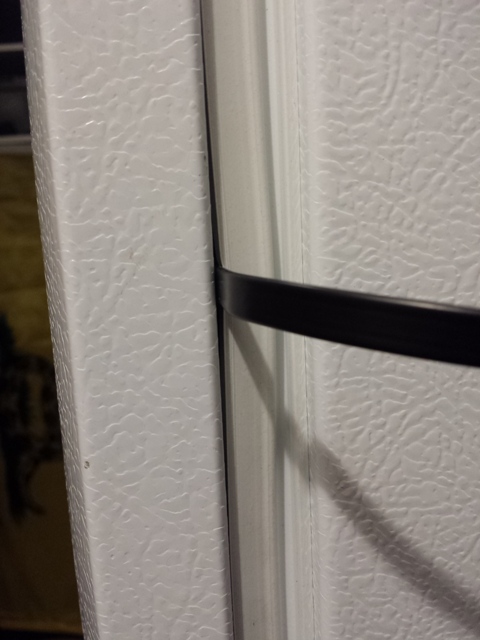
The black line above is my MySensors sensor. (you can see it in the project pics above) It's a thin esata cable which allowed me to go behind the gasket.
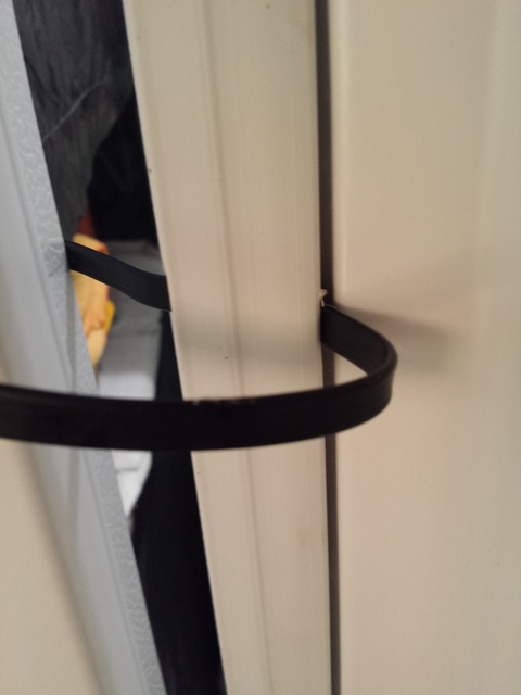
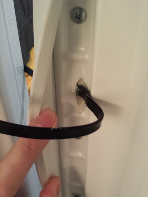
Using a Dremel, I was able easily cut a slice out of the door liner.
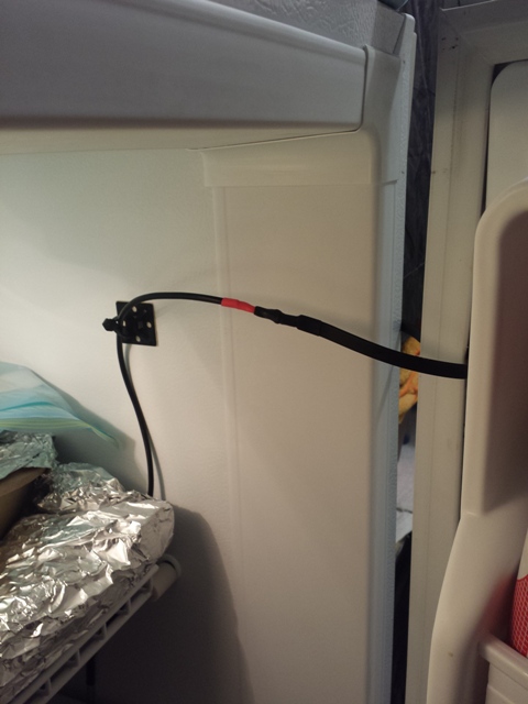
Now of course this would only be acceptable by the wife if it's in the utility room... :-)
Depending on the make and model of your unit, I might be able to get the refrigeration and wiring layout location for you...
-
Thanks @bjornhallberg, In my testing on my freezer, I found, through a bit of trial an error, that stranded 26awg wire with the outer jacket removed gave me very good results. I ran the logger for 3 days with no noticeable problem.
Keep in mind this logger will be used by us as a diagnostic tool, (I work for an HA HVAC/R company) so it's use is temporary. If you are interested in a permanent solution look at these pics:

The black line above is my MySensors sensor. (you can see it in the project pics above) It's a thin esata cable which allowed me to go behind the gasket.


Using a Dremel, I was able easily cut a slice out of the door liner.

Now of course this would only be acceptable by the wife if it's in the utility room... :-)
Depending on the make and model of your unit, I might be able to get the refrigeration and wiring layout location for you...
-
@ServiceXp said:
only be acceptable by the wife if it's in the utility room...
You can read my mind! That's exactly what I thought when looking at your pictures! ;-)
-
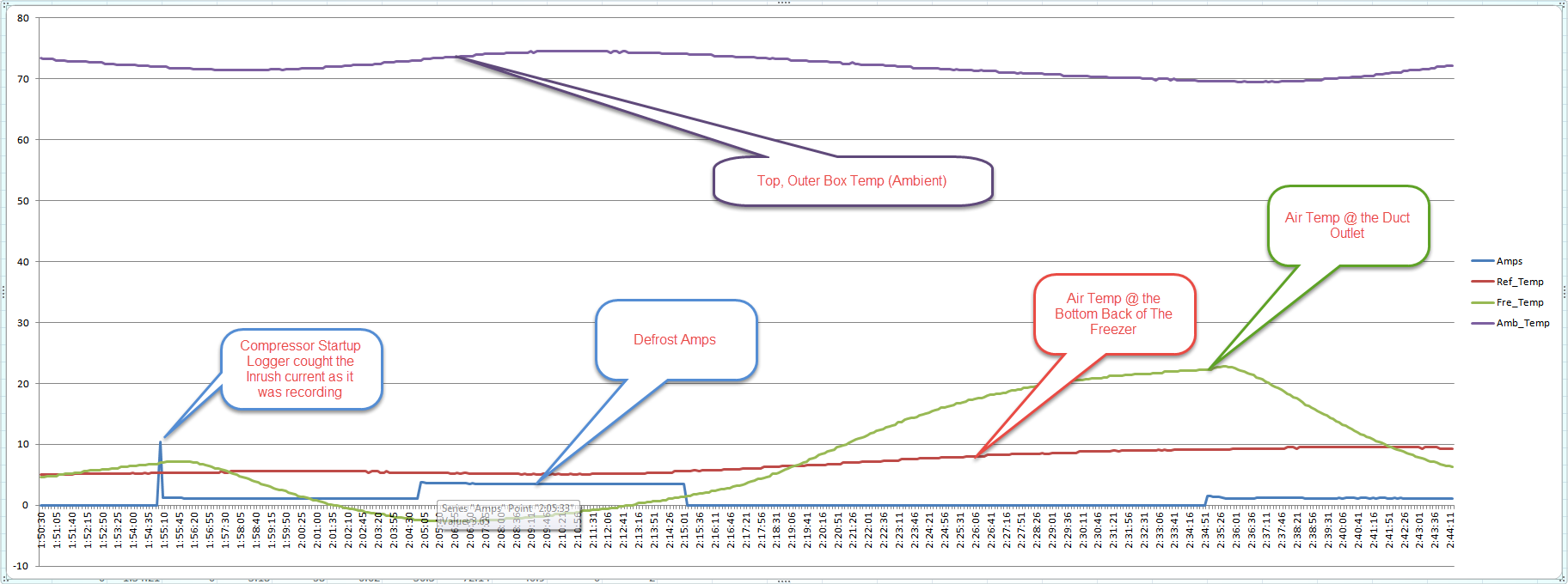
Some Graph Examples: (I'm not very good when it comes to good graphs so....) :-)

Taking a Closer look at the temp spike.
-
This is quite fantastic, thanks for the write up!I would be interested in the current monitoring tied in with MySensors though, at least in my current state that would come before refrigeration data.
I have been looking for a good whole home current monitoring solution.
-
Is the light sensor for (indirectly) detecting when the door is open?
(Or maybe it's to answer the age old question - does the light REALLY go off when you close the door :-) )
-
Thanks for sharing this!
Oddly, what this inspires in me is the desire to monitor ice chests when camping, which have much more variation and uncertainty than our home refrigerator.
Like - block ice lasts longer than crushed, but how much does that affect the temperature curves as it melts? How much colder is the bottom of the chest than the top? How do our various ice chests compare? How much does cold meltwater help or harm the cooling? How much effect does opening the lid have? (Eg: for given conditions, perhaps each time of opening the top for 30 seconds moves the temp and melt curve along as much as 20 minutes of sealed operation - or what?).
I'm thinking two internal temps (maybe humidity) and light; one or two external temps (eg: top and side or bottom) and maybe light (to detect sunlight). It would need to be battery powered (externally), but wouldn't need to run for so long. For at least the bottom inside measurements, would probably need a waterproof sealed 18B20 probe. Would need entry wires sturdy enough to handle friction from a lid sliding reather than pressing shut, or an acceptable through-wall technique (which allows the electronics to be detached and is sufficiently sealed.
-
Is the light sensor for (indirectly) detecting when the door is open?
(Or maybe it's to answer the age old question - does the light REALLY go off when you close the door :-) )
-
Well, After some more testing I found a hardware bug in my particular build. I started testing the unit in a cold environment (having the controller in lower temps (~50F)) and discovered that the 4 pin audio jack connections fail. Not exactly sure why, but I'll post back my 'solution" once I figure it out myself..... (:P)
-
Well I changed the connection type for the sensors due to the above issue.
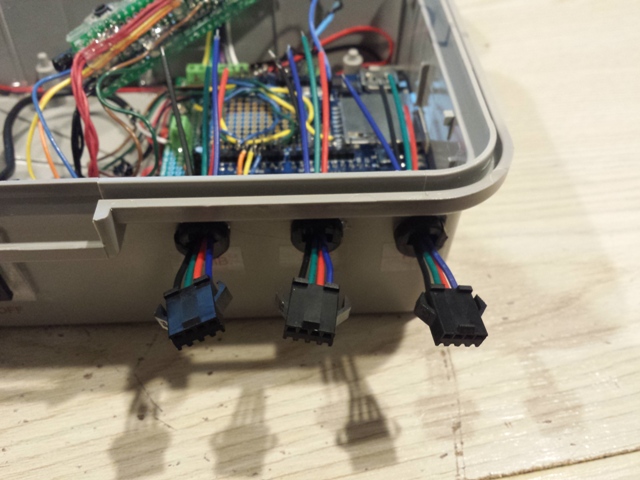
Tested and again after 2.5 days, it locked out on a sensor com error. So after some thought, I realized, (not sure why I didn't before) the system is not going to be 100% bullet proof, so instead of moving to a hard fault, I recoded the error handling section of the sketch to attempt to handle the occasional hiccups in reading the sensors. Pushed new sketch to Github and am testing now.
It will interesting to see just how many times the readings fail.
I shall see.....
