💬 MySensors NRF5 Platform


  • What is the best way to use a pin interrupt to wake up form a sleep?

    like for instance, I got some sort of motion connected to PIN 8.


  • Hero Member

    The source code for the PIR project gives one possible answer.


  • @neverdie
    I've been dealing with that code but for some reason, I don't get it to work, code-wise it seems I'm lacking..

    First i get this error: struct NRF_UARTE_Type' has no member named 'TASKS_SUSPEND
    And when I comment that out it seems like its not waking up.

    I made a test sketch, which reported the status every 1000ms. this worked accurately for the last 3 days so it doesn't look like it is a sensor problem.

    So my hope was that there was an easier methode available..


  • Hero Member

    @omemanti Sounds like maybe you're either missing a library or else not linking to one that's required.


  • @neverdie

    What am I missing, I just reinstalled the whole shabang.

    • Arduino IDE
    • Sandeep
    • Mysensors 2.2.0

    thats all there is installed..


  • Hero Member

    @omemanti You want the mysensors development fork.


  • Hero Member


  • @neverdie

    • removed 2.2.0 => installed 2.2.1 Alpha.
    • boards check.

    Still:

    error: 'struct NRF_UARTE_Type' has no member named 'TASKS_SUSPEND'
    
       NRF_UARTE0->TASKS_SUSPEND = 1;
    
                   ^
    
    exit status 1
    'struct NRF_UARTE_Type' has no member named 'TASKS_SUSPEND'```

  • Plugin Developer

    Let's say I've just bought a $2,50 NRF52 board.

    Does anyone know a good tutorial for absolute beginners?

    For example:

    • I have no idea what a softdevice is. Should I know?
    • I don't know what hardware I need. A normal serial adapter or an ST-link? Should I hack an STM32 into a black magic probe (whatever that is..), or is that for power users?
    • To what pins do I connect to upload a sketch?
    • How are you connecting wires onto the package? Just hotglue and very steady hands? Some cheap adapter or board? Any tips and tricks?
    • There's something about text files that define how the pins work? But the serial pins are always the same? Where does the text-file go? What flavours are there? Which is the most popular?
    • What boards should I enable in the Arduino IDE?
    • How do I debug my sketch? Does the serial monitor work?
    • Do I still need the development version of MySensors now that we are at V2.2?
    • Do I need to set anything in MySensors?
    • Are encryption, signing and the simple options to do this supported?
    • What can it do? Can I connect a 5v sensor to it? Can it power things in the way that an Arduino can?

  • Contest Winner

    @alowhum all security functionality currently available for MySensors is supported om nrf52. There is nothing in the security road map that will not be supported on nrf52. The MAY be features that work best with a security peripheral but there will always be software compatible alternatives for released features that can operate on nrf52 unless it is natively supported by the HW peripherals in the chip.


  • Hardware Contributor

    @alowhum you can start with this:
    https://forum.mysensors.org/topic/6705/mysensors-nrf5-platform/1
    and
    https://forum.mysensors.org/topic/7869/start-with-nrf5-is-very-simple/1

    But you should also check the NRF5 information on Nordic website.
    In short it's 3.3V max (so no 5V peripherals directly), you need to program through the 2 SWD pins (SWDCLK and SWDIO) and you have different options for that, for debugging use a FTDI adapter and connect it to the pins you have assigned as TX/RX.


  • Hardware Contributor

    Hello,

    has someone successfully used VisualMicro with the MySensors NRF5 boards ?
    In the board selector dropdown list I can select any board, including NRF5 boards like "Generic NRF51" or "BBC Microbit", except when I select MySensors NRF51 or NRF52 boards, then it's not doing anything and keeping the previous selected board. I have a message in the status bar saying "the first available board has been selected" and that's all, I don't find anything related to VisualMicro with this error message in Google.
    I have tried with both 0.1 and 0.3 versions of the boards, and with both "Arduino 1.6/1.9" and "Visual Micro (No IDE)" IDE selections.


  • I like VisualMicro and think I got this to work but was mostly using plain Arduino to keep things simple while figuring it out. I haven't worked on an NRF5 board for a few weeks. I will check my setup. Might be a day or two before I can get back to it.


  • @nca78
    No. I was mistaken. I have the same issue as you. I used the arduino program with the MySensors NRF5. I would like to get this to work also. Please post if you find a solution.


  • Hardware Contributor

    @nagelc thank you for taking the time to check, I'll go with Arduino for NRF5 at the moment and keep that for a moment when I'll be more keen on fixing technical problems 🙂


  • What are people using for a gateway with these?

    I'm currently using this from @NeverDie , which seems to work for the most part, but I'm getting a lot of connection errors:

    2018-04-18 18:27:35 ERROR (Thread-2) [mysensors.gateway_tcp] Receive from server failed.
    
    2018-04-18 18:27:35 INFO (Thread-2) [mysensors.gateway_tcp] Closing socket at ('10.0.50.100', 2323).
    2018-04-18 18:27:35 INFO (Thread-2) [mysensors.gateway_tcp] Socket closed at ('10.0.50.100', 2323).
    2018-04-18 18:27:35 INFO (Thread-2) [mysensors.gateway_tcp] Trying to connect to ('10.0.50.100', 2323)
    2018-04-18 18:27:35 INFO (Thread-2) [mysensors.gateway_tcp] Connected to ('10.0.50.100', 2323)
    2018-04-18 18:27:52 INFO (Thread-2) [mysensors.gateway_tcp] Closing socket at ('10.0.50.100', 2323).
    

    They seem to come up about 75% of the time when the gateway receives a message from a node.

    I thought it might be a power thing, so I messed around with a few caps and a separate power source for the hat but nothing seems to have made a difference.

    Everything seems to work despite this, but I don't really want my log to be filled with these errors if I can help it.

    Has anyone attempted to build a wired gateway or anything similar?


  • @shodney i used this one for a couple of tests. I resoldered the caps near the top and connected a new antenna. Works pretty well for testing purposes. I expect some pcb's a week ago😏 for some further testing.


  • Hero Member

    The gateway I've used has been:
    https://www.openhardware.io/view/491/PA-LNA-nRF52832-ESP-LINK-Shield-for-Wemos-D1-Mini-ESP8266
    I haven't noticed any problems.


  • @nca78 I posted to the VisualMicro forum. They responded right away. They are going to fix it in the next release. Something to do with internal naming conventions.


  • Plugin Developer

    I've created a BME280 node along the lines of the NRF5 beginners guide I posted.

    But something odd is happening. The node works great for about 8 hours.. and then it stops working.

    I already changed the power supply, but the same thing happens.

    Could it be a memory leak?


  • Hero Member

    @alowhum I'm not sure the function call that reveals that amount of free memory available, but I'm sure there must be one. Logging that as a diagnostic would reveal whether you have a memory leak in your code.


  • @nca78 I downloaded the latest update to VisualMicro last night and had mixed success. I can now pick the MyboardNRF5 boards, but run into a compile error where it cannot find the build directory. Have you tried it yet?


  • Hardware Contributor

    @nagelc not yet I will give it a try tomorrow.


  • Hero Member

    @d00616 Will everything work the same on the nRF52840?

    Has anyone tried it?


  • Contest Winner

    @neverdie said in 💬 MySensors NRF5 Platform:

    @d00616 Will everything work the same on the nRF52840?
    Has anyone tried it?

    Yes. At the moment, I have no time to finish my work on supporting the nrf52840. In my Repository https://github.com/d00616/ArduinoHwNRF5 you can find my last state. All 840 ports P0 (0-31) and P1 (62-64) should be usable as GPIO but there is no support using the P1 ports with any pin mapping component like UART, I2C....

    The second change in my last commit is mcuboot. A bootloader compiled with Zephyr. Firmware can be upgraded OTA using MYSController with some enhancements (ask @tekka about the correct version). Firmware transmision works well but, at the moment my mcuboot port don't work. The memory layout between zephyr and arduino is different. The application cashes after start. I think it's a problem with different memory layout between Arduino and Zephyr.

    For NRF52 MCUs the memory problem can be solved by moving the interrupt vector register to the IV location in the image and setting the SP register to the correct value. Maybe the starting code of ArduinoHwNRF5 is the correct position, so this mcuboot version can be used for Arduino and Zephyr Software.

    If moving the SP to the correct position doesn't help, for NRF51 the Arduino linker scripts must be changed. I think there is only a small change required, but I have no idea about how to do this.

    It's welcome if someone can finish this work.


  • Hero Member

    @d00616 Argh, that's a pity if the pin mapping doesn't yet work, because it means I won't be able to do the drop-in upgrades from the Fanstel nRF52832 to the Fanstel nRF52840 as I had hoped to do. It means I would have to re-do all the PCB's if I want to upgrade to nRF52840. 😞 I guess I would have to figure out some other way to remap the pins.


  • I have a couple of BT840s on order, also hoping for the easy upgrade. It looks like the pins have the same functionality as the BT832 except for pins 11, 12, and 13 (and 14 if you weren't using it for reset). I wonder why they did not just keep them all the same.


  • Contest Winner

    Sorry wrong wording. All P0 ports can be mapped. But to map P1 ports there is additional code required which does'n exists in the Arduino port.


  • Contest Winner

    If someone try to work on mcuboot compatibility. Maybe only the IV is the problem. For NRF52 the IV can be moved to the beginning of the image, but the nRF51 IV is in the mcuboot rage.


  • Hero Member

    @nagelc According to the Fanstel documentation, "Except the 19 pins in solid black dots, BT840F and BT832F is hardware pin to pin compatible. " So, if I'm understanding correctly, it appears that the the castellated pins should be exactly the same, and those are the only ones I'm able to solder anyway.

    This is quoting from their v1.1 datasheet, which is dated August, 2018: https://static1.squarespace.com/static/561459a2e4b0b39f5cefa12e/t/5b75e95daa4a99c02bbce364/1534454116506/BlueNor_BT840F_datasheets.pdf


  • Hero Member

    Oh, I see now. p18 is the reset pin on the nRF52840 now, not p21 as on the nRF52832. However, both share the same physical location on the Fanstel modules. OK, so in that case, I guess it only matters if you want to use the reset pin as an gpio pin instead. Likewise, the LED has the same physical pin location on the module, but it's pin 020 on the nRF52832 and pin p13 on the nRF52840.

    Well, if we can just somehow manage to upload a simple blink sketch to the nRF52840 from the Arduino IDE, then I suppose I can live with wherever else is different. It's getting some kind of "hello world" compiled, uploaded, and running that's always the hardest part with these things. Once that's in place, one can chip away at the rest of it. i.e. it looks like I can re-use my same PCB's with the nRF52840 and just make some software changes to make it work. I'd still count that as good news. 🙂


  • Hero Member


  • Contest Winner

    @neverdie said in 💬 MySensors NRF5 Platform:

    @d00616 I guess this is what you mean by Zephyr? http://docs.zephyrproject.org/boards/arm/nrf52840_pca10059/doc/nrf52840_pca10059.html?highlight=nrf52840

    With Zephyr, I mean the Zephyr OS. This board definition is part of a newer Zephyr Version, I had used to compile mcuboot. This was ~7 Month ago.


  • Hardware Contributor

    @NeverDie I think you might have no problem at getting blink working. On this pic, the nrf52840dk was running mysensors https://forum.mysensors.org/post/79460 (it was a simple counter test).
    But sure nrf52840 is "new", and each new mcu always needs time to get all features working..+the maintenance..the more the merrier, not sure 😄


  • Hero Member

    @scalz said in 💬 MySensors NRF5 Platform:

    nrf52840dk

    You're sure it was the nrf52840dk? I didn't think it had been released until fairly recently, whereas your post was 10 months ago. Maybe it was the pre-dk? I guess either way it would support your point. I just want to be sure you didn't mean the nrf52832dk?

    I guess since the MCU seems to be the same (?), there's a good chance it may work.


  • Hardware Contributor

    @NeverDie yes. on the pic, pca10056 (so it's nrf52840), that's the only dk I have (nice dev board). it was using d00616 mysensors driver.


  • Hero Member

    @scalz said in 💬 MySensors NRF5 Platform:

    @NeverDie yes. on the pic, pca10056 (so it's nrf52840), that's the only dk I have (nice dev board). it was using d00616 mysensors driver.

    That's great! Were you able to have it send/receive to/from nRF52832's as well?


  • Hardware Contributor

    @NeverDie on the pic there was multiple nrf52832 nodes, only the dk was 840, the gw had nrf24.
    Atm, the nrf52840 arduino core is not finished, so the additional features 840 can provide (security, zigbee etc), won't be available soon for arduino+mysensors. And there is still work to do for getting all 832 features. I think for the moment 840 is maybe interesting for the additional range only, or if you don't have enough memory with a 832..
    Sometimes I'm wondering what's the best?? focusing and getting a solid core/framework for a very few mcu, or handling lot of mcus 💪 with unfinished cores (+lot of maintenance)?
    But I agree with you, tech stuff is sexy (I'm not the last at testing lot of mcus though) 😉


  • Hero Member

    @scalz I'm still wondering: was your 840 able to send and receive with the 832's?

    In the near-term I'd settle for the additional range that the 840 has to offer. IIRC, it has a 4db higher Tx and a 4db better Rx than the 832. So, 840 to 840 should have an 8db better link budget, which is significant.


  • Hardware Contributor

    @NeverDie I think I tried once, but I'm not sure; so take it as 'nope' 🙂 But all nrf were compatible as they were talking to gw..
    I agree 840 should have more range. but that's just datasheet numbers, in 2.4ghz band, and still not 20dB. for a direct replacement, you win range sure. but good 832 design choices can work as good as bad 840 design choices.
    I have a different strategy. and I already got 832s ic for 2€. Because bt840f has not really a nice price imho. for what ?? a mcu few passives, pcb antenna, and just a few IOs exposed to castellated pins (I have no time to debug when there is a bad solder point on bottom pads..).
    bt840 is more affordable but you loose all the range.
    Then, you can find module from chinese brands. price is ok too. but the same lower range. On my side I would prefer spend money on good sensors.


  • Hero Member

    @scalz Fanstel has by far the best antenna design in its F series of all the nRF52 modules that I've tested (well, at least on an nRF52832 module, and I presume it carries over to the nRF52840 as well), so you do get some extra value for the extra money. Of course, if you can do your own, then you don't need Fanstel. I'd say you have above pretty good skills when it comes both to soldering and PCB antenna design, and so you are better able to build rather than buy. That's great! In my case, for the nRF52 chips, I pretty much have to buy modules instead. I suspect the same is true for most people here.


  • Hero Member

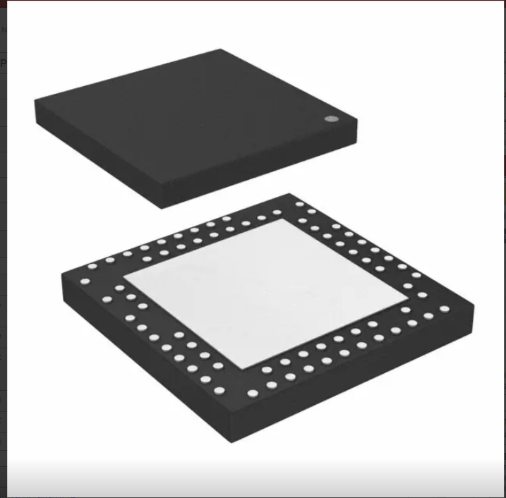
    Actually, the nRF52840 chip looks incredibly hard to solder (well, to me anyway):
    0_1536631559017_nrf52840_chip.png


  • Plugin Developer

    Has anyone got MySensors running on a Micro-bit?

    I'd like to create a simple motion sensor for MySensors, and a microbit has all I need on board.

    In general, MySensors and MicroBit could be a great combination for education and fun?


  • Hero Member

    @alowhum Sounds like a good idea.


  • Hardware Contributor

    @alowhum it's an nrf51822 so you can, but the interrupt management on nrf51822/arduino needs some tweaking to get really low power.


  • Plugin Developer

    @Nca78 I ordered one, it should arrive tomorrow. Would you be willing to help me out in making it ultra low power once I get started?


  • Hardware Contributor

    @alowhum said in 💬 MySensors NRF5 Platform:

    @Nca78 I ordered one, it should arrive tomorrow. Would you be willing to help me out in making it ultra low power once I get started?

    If you're planning to use only one interrupt, it will not be very difficult, @NeverDie made some code for the low power comparator, search "LPCOMP" to find the posts in the NRF5 thread.
    The constraint is you need the interrupt pin to be in the range of 1-8 (not 100% sure, you need to double check what pin numbers are available with LPCOMP).


  • Are there any plans to update the mysensors nRF5 boards definition to now support the nRF52840? I saw that Adafruit have now added support and are offering a feather based on this module https://www.adafruit.com/product/4062. There is also this listing for a module with 1.27 mm spacing on Alibaba https://www.alibaba.com/product-detail/low-energy-mesh-network-UART-module_60816297852.html


  • I thought I mastered nrf5 platform bit it looks I am not.
    I have a PCB where i2c sensor is hardwired to po30 and po31 of nrf52832.
    What changes I have to make in MyBoardNRF5.cpp?
    Shall I bring lines 28/29 that have "A4" and "A5" in their desciption to 30th and 31st position in the list?


  • I think you can just set the I2C pins in MyBoardNRF5.h without remapping the pins in MyBoardNRF5.cpp.
    Look in MyBoardNRF5.h, under the Wire Interfaces section. Set SDL and SCA to 30 and 31 as appropriate for your board.


Suggested Topics

0
Online

11.2k
Users

11.1k
Topics

112.5k
Posts