What did you build today (Pictures) ?
-
I'm in the mid of building a more complex sensor setup for the chicken coop, where I use dupont cables all over (actually, it's more or less the first sensor that I use them in..) I do not expect to poke around in the wires, after I have mounted it in the chicken coop at some point in time. So I recon it's going to be ok.. (And it will be hot glued into a large weatherproof junction box)
-
Rule #1 from what I've read is to keep connections as short as possible, especially when radio is involved. However, if you're not suffering from using long wires, then, well, I guess why not? If this is a prevailing belief, then maybe it does at least partially explain the remarkably low uptake of openhardware.io projects.
-
I personally use only short dupont wires as they give you some flexibility but without too much "spaghetti" wiring

-
Guys, you are deviating from the OPs thread "rules"

-
I guess the thread can evolve the way it does - but in the same time, if there are a interesting ongoing discussion all mods are more than welcome to lift that discussion out for a own thread and if so we can keep this thread as intended?
-
Here is a project I finished this weekend.... 5m LED strip controller (the cover is off for the photo)
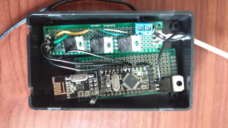
I think you can say I've come quite far since my first ever arduino build... lol
![0_1508764679200_2016-02-09-21h05m49-[DSC_0001].jpg](/assets/uploads/files/1508764680235-2016-02-09-21h05m49-dsc_0001-resized.jpeg)
-
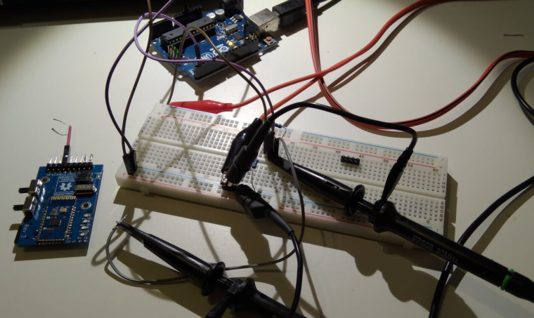
Last night i continued improving my Logger (mostly protecting the serial input and make sure it can handle incoming serial logic from everything from 2.5v to 5v into my 3.3v system). I finally bought myself a oscilloscope so now I have the longest list possible of things I want to improve... (EasyPCB series, Booster performance?, some relays... the list goes on).
-
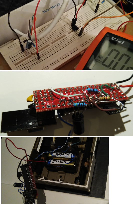
Tonight I changed the mechanic trigger to a optocoupler on my doorbell node. I went with some sort of half good solution.
8v AC (Doorbell activated) -> Diode (Not a full bridge, just a support capacitor) -> Voltage divider -> optocoupler > D3. Worked out great, but might be one of the ugliest nodes I have
Testing/Soldering/Deployment:
-
I changed the form of my integrated nRF52832-protoboard:
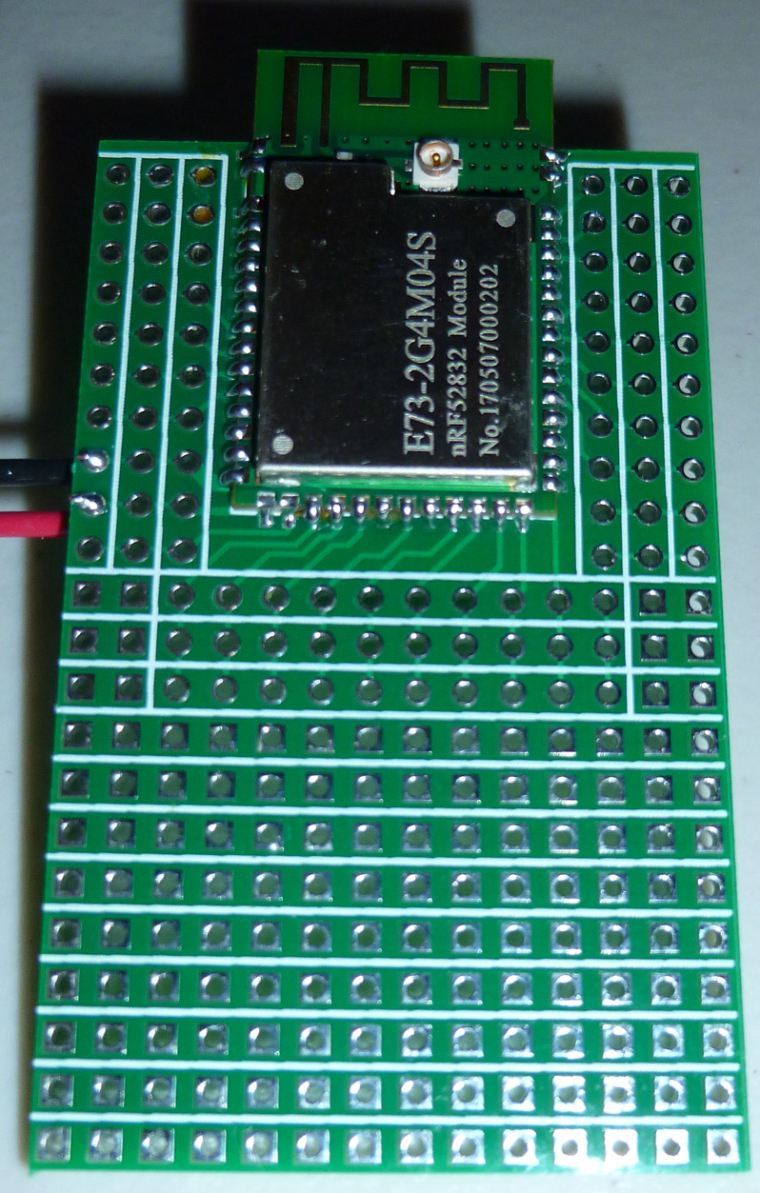
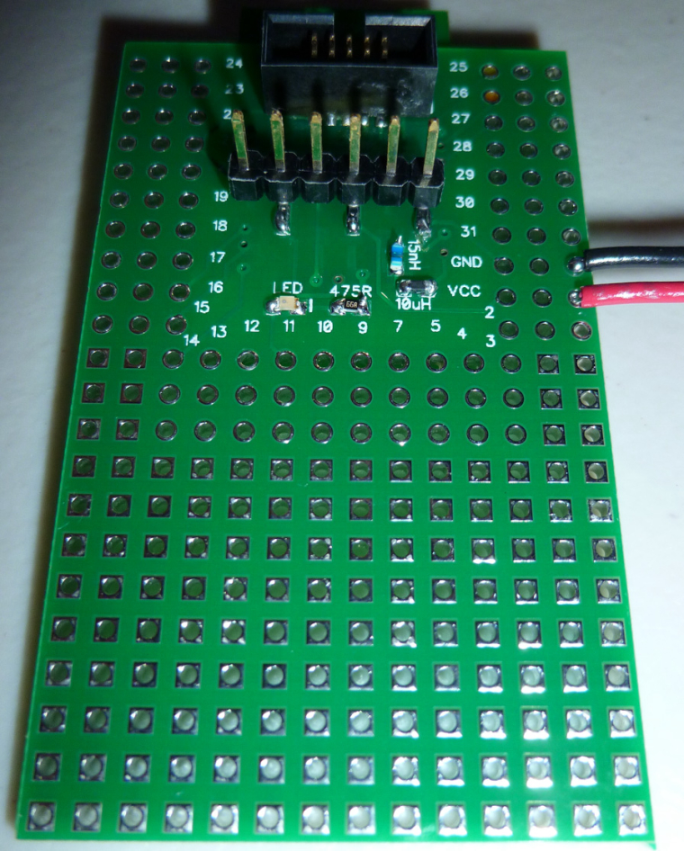
Previously, I was using: https://www.openhardware.io/view/472/Ebyte-nRF52832-Prototyping-Board
-
Today I made some small changes to a battery node. Once again I had copy/pasted all battery code but forgot the internalReference in setup() (since I copy from another node sketch). So I now created a dedicated file for battery code I can use to copy from... and once again I remembered I'm not a coder... But it works.
https://github.com/sundberg84/MySensors2.0.0/blob/master/BatteryMeasurer/BatteryMeasurer.ino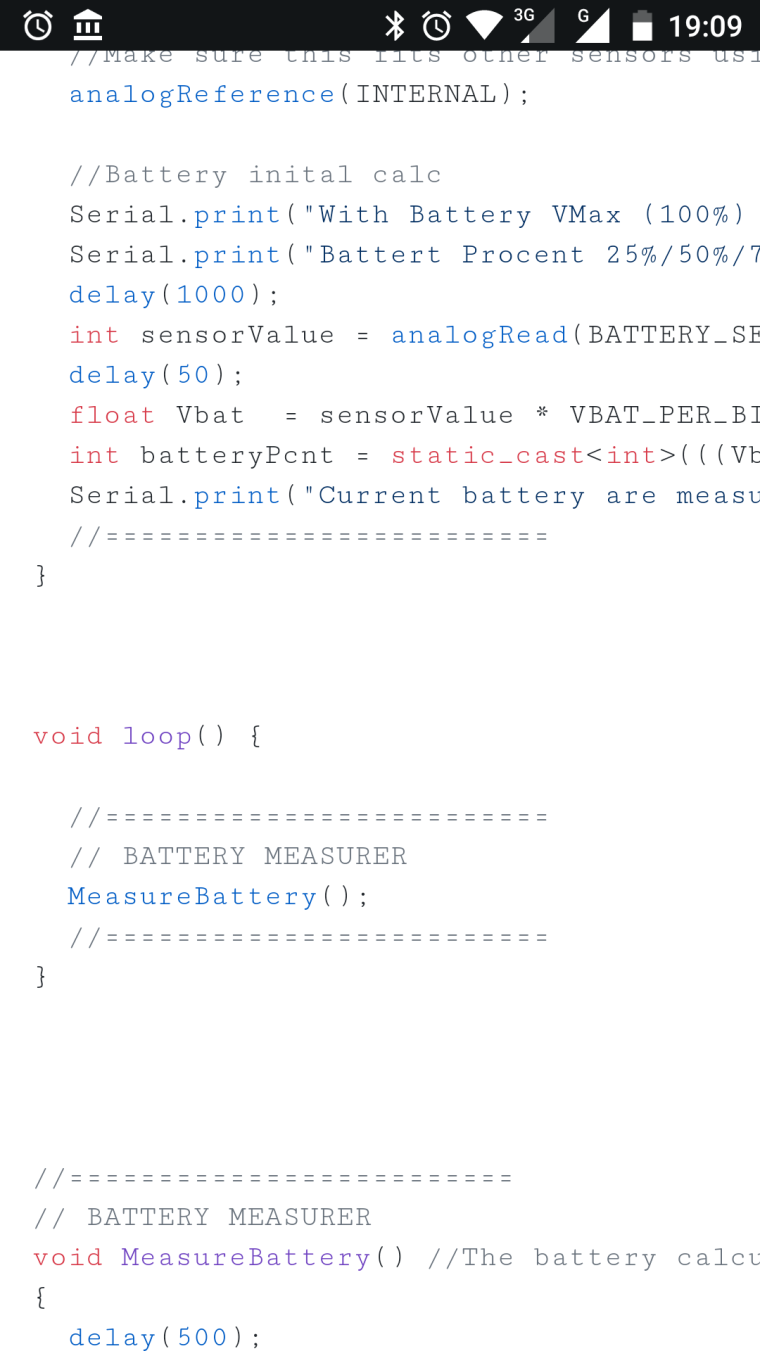
-
@sundberg84 Not to be critical or get off topic, but it's percent, not procent
-
Simple RS485 gateway and node for two BME280 sensors:
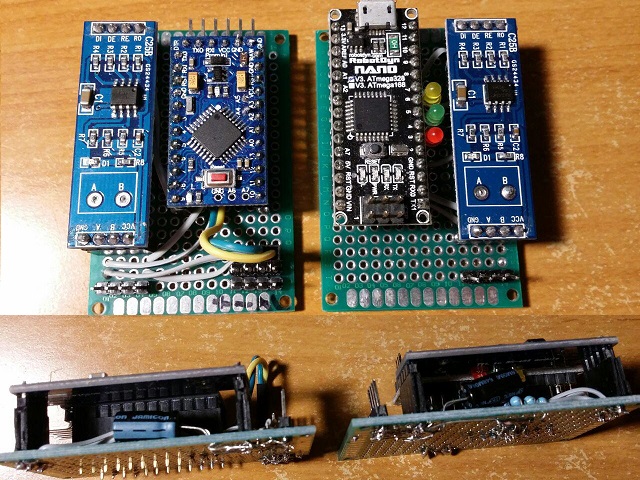
-
Made a small tool to simplify the extraction of serial debug data from a 10-pin IDC connector and reading it from a typical 6-pin FTDI module.
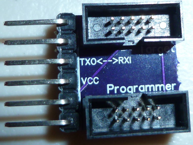
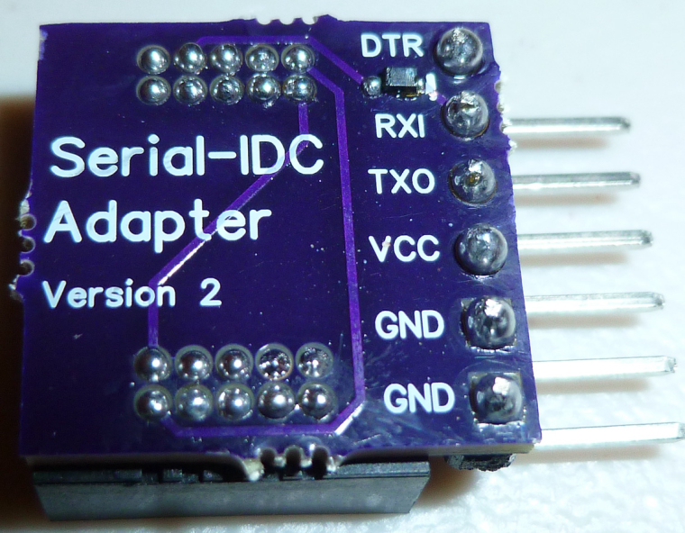
The 10-pin IDC connector is what's most commonly used for programming nRF5x modules.
-
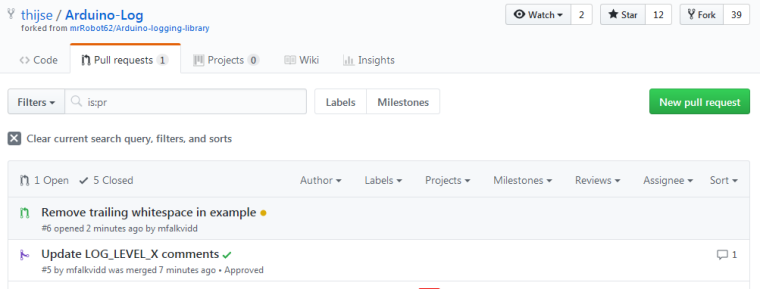
Not really MySensors-related, but I found a nice logging library for Arduino that I'm using in a project. The library was orphaned some time ago, but now has a new maintainer. I assisted with an update of the documentation and some source code cleanup.
-
I made an nRF52832 board today with 5 different colored LED's on it: red, green, yellow, orange, and blue. Mostly I think it may be useful while debugging code. All the LED's except for blue emit light all the way down to 1.8v source voltage, so it's good for battery powered operation also. The blue lights up all the way down to 2.4v, and I had to grapple with a 0403 LED to get that low of a voltage for a blue LED. In the end it was so tiny that I couldn't see the polarity of it, so I hit on the idea of running a blink program and seeing whether it would light up just before I soldered it in place. That worked.

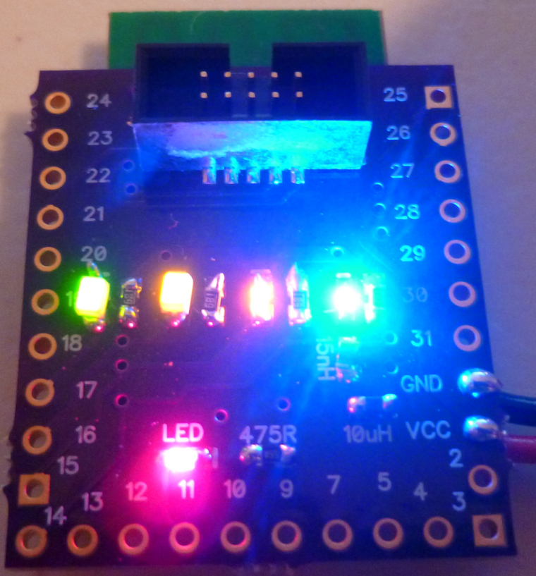
Also, this board channels its serial output over the 10-pin IDC connector, so I used the tool I posted yesterday to read it. Works great, and now I don't have a six pin FTDI connector cluttering up the PCB.

-
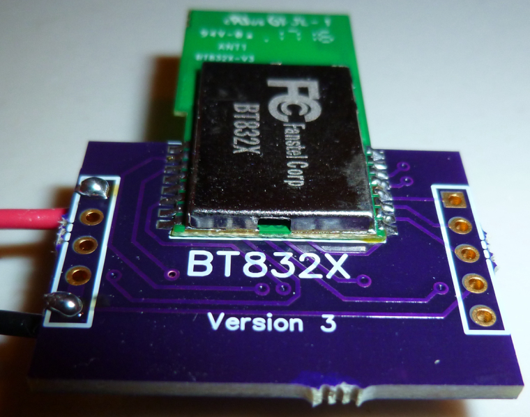
Today my boards for the BT832X (that's an nRF52832 with both PA and LNA) arrived from OSH PARK, so I put one together to try it out:
-
A (long) time ago I had my own Android app which talked xmlrpc to a Python script, which talked serial with my Arduino which in his turn talked 433 Mhz to our outlets turning lights on and off. All was dandy until Android 4 came along and something stopped working security wise and we were send back into the middle ages.
Today I successfully got MySensors working enabling me to read temp/hum from a node and letting me send Elro signals into the air over 433Mhz from OpenHAB2. Now I can scale, extend and upgrade my sensors and actuators I can move forward and start improving our home.

-
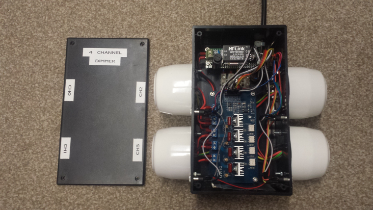
Today I completed the installation of the first of my 4 channel 240V LED light dimmers. This is installed in the roof and supports 4 buttons to turn on/off/increase/decrease each channel. It uses an AC zero crossing detector circuit and can be configured for leading or trailing edge dimming.
-
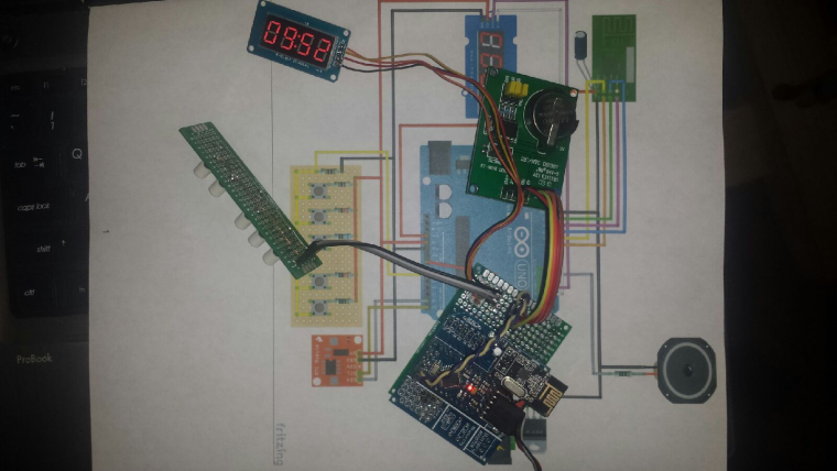
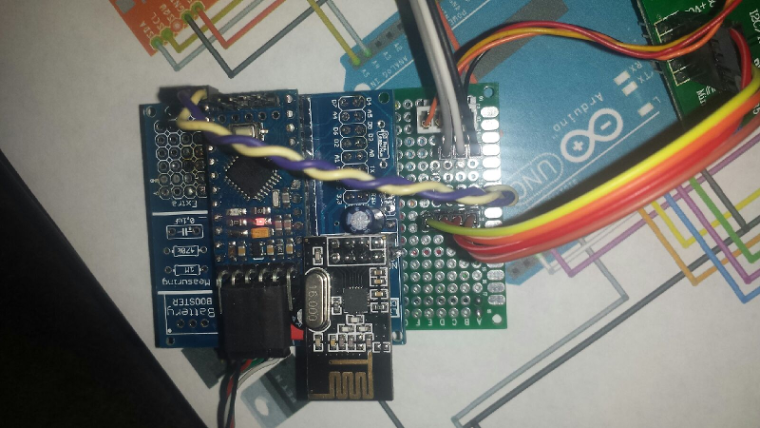
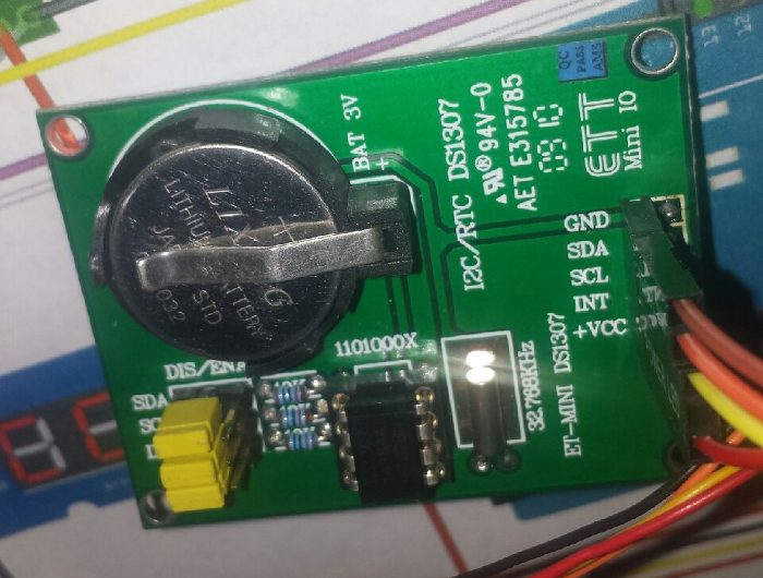
Working on a smart clock project. Need to make some major code modifications to the example, but should work. I have a test sketch that just passes the time from the RTC to the display, so I know that is all working.
-
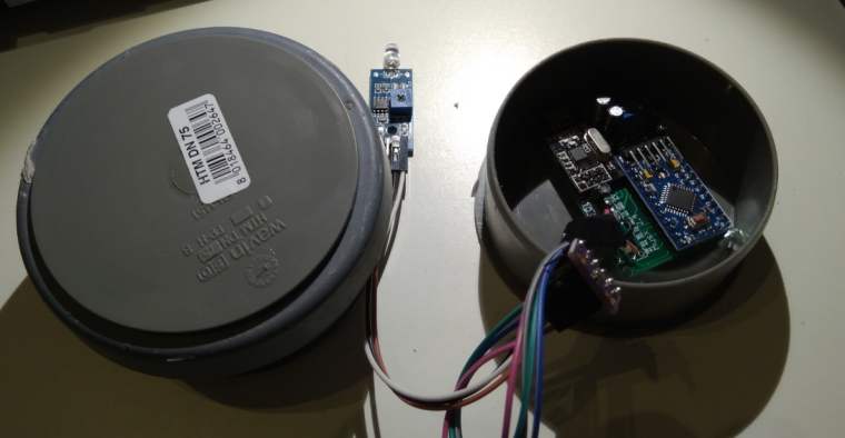
Last night I made a enclosure to my new outdoor weather station/node. It is made from 2x 70mm sewer pipe end caps and a small sewer pipe to keep them together. Works surprisingly great and looks good.
Now its painted black and drying - lets hope I can find any daylight this week and mount/deploy it.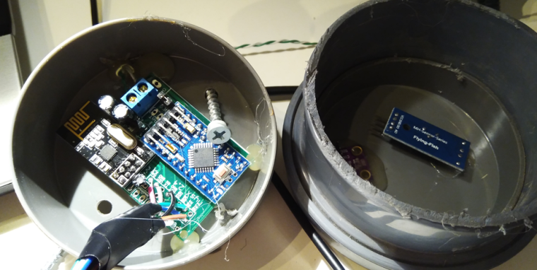
-
@sundberg84 If this is going to be out in the sun, I would think you'd want it white. Black is going to heat up your electronics quite a bit.
-
@dbemowsk - No worries, no sun! All below a roof so I get shade all the day. The roof is black so I need it to blend in as well.
-
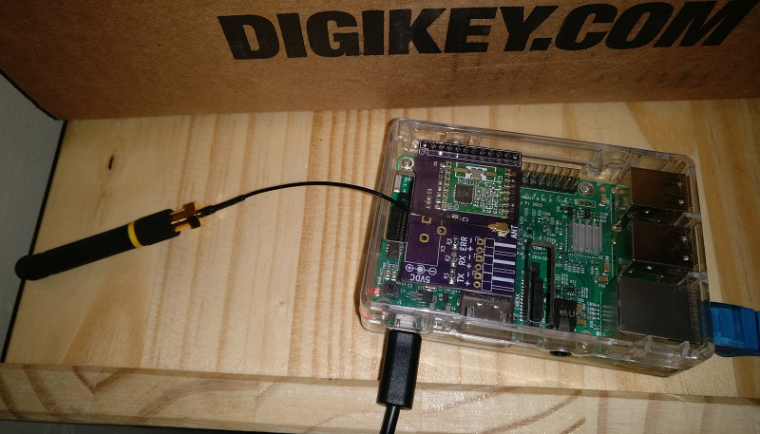
I soldered together the PCB I made for my RFM69 Pi Gateway. Next step is to put it in a nice enclosure
-
A set of Node-Red nodes to decode OpenTherm messages produced by thermostats and Central Heating systems: https://github.com/Yveaux/node-red-contrib-opentherm
It can e.g. replace the OpenTherm Monitor software from otgw by InfluxDB/Grafana

Not a MySensors project, but nice anyway

-
I did a quick port of my earlier project to make a breakout board for the BC832:
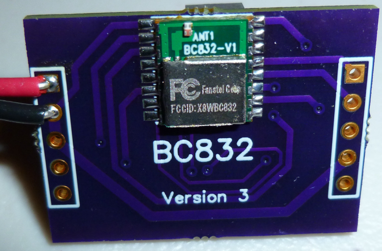
What's interesting about the BC832 is that it is a complete nRF52832 system: 32-bit ARM Cortex 4, wireless, flash, memory, RTC, and antenna, and the whole thing is smaller than a dime:

Of course, my ported breakout board, being as large as it is, doesn't do it justice. That's OK, though, because its main purpose is just to take the BC832 for a test drive.
-
Power (lower half) and external interfaces (upper half) PCB for my "entrance" MySensors node (unregulated voltage, +5V, +3.3V, doorbell detector, electronic door lock status, temperature, etc). I'm using conventional 220V=>6V transformers as main power supply and as simple 220V presence detector for doorbell.
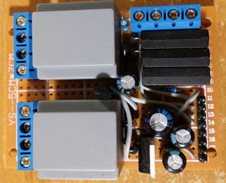
-
Let me present - How NOT to deploy a MySensors Node! Here is how you do: 1) Skrew everything solid to a wall 2) Power it up and make sure you have shorted a SDA / GND or VCC on your BMP sensor just because you dont doublecheck the colors 3)Forget to enable # My debug 4)Fetch your last BMP sensor but drop it on the lawn (pitch dark outside) 5) Spend 30min with a flashligh in 5dgr C searching for the sensor and try it out once you find it. 6) Nothing works so Un-screw everything and connect it to FTDI inside at your computer, reupload the sketch with debug. - Now everything works fine (with the first sensor) for some unknown reason. 7) Skrew everything back again!
 Find out the BMP sensor is not working 9) Debug Serial (atleast I got to use my new logger) 10) Find out a short on the MysX connector due to bent wire.
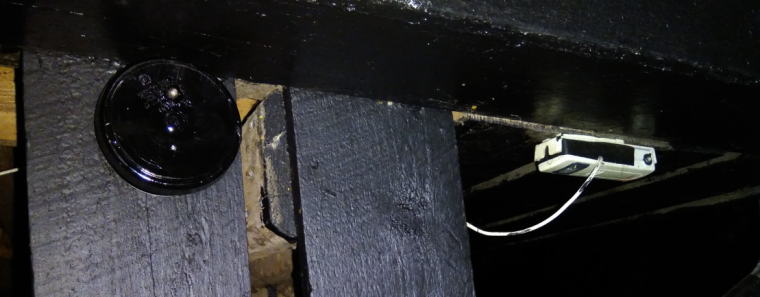
New and old sensor - side by side.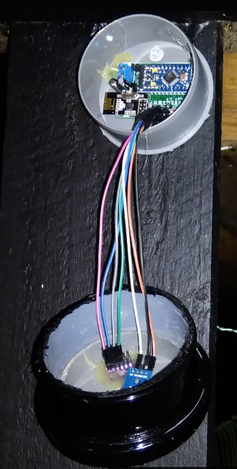
-
@sundberg84 poor guy... +1 for persistence though

-
@sundberg84 Time for you to do a new PCB so you can get rid of all that wiring....
-
@NeverDie Im waiting for someone to create those MysX shields so I just can attach them to my EasyPCB.
-
@sundberg84 Where is the definitive description of MysX? Perhaps I might have a go at making some shields with it, if I knew what it was.
-
@NeverDie not sure if https://www.mysensors.org/hardware/mysx is definitive but it should be a good start
-
@mfalkvidd Wow, MYSX 2.6 is a 22 pin connector! That wouldn't be practical on a small shield (such as a pro mini size shield) I don't think.
-
@NeverDie from what I've understood, the idea is that you pick the lowest revision that can support the features you want. So you can select 8, 10, 12, 14, 16, 20 or 22 pins.
-
Non the less, if we start having a more standardized environment on the mysx connector, it would be best. But we are going OT.
-
Put together this pro mini nRF24 shield for testing...
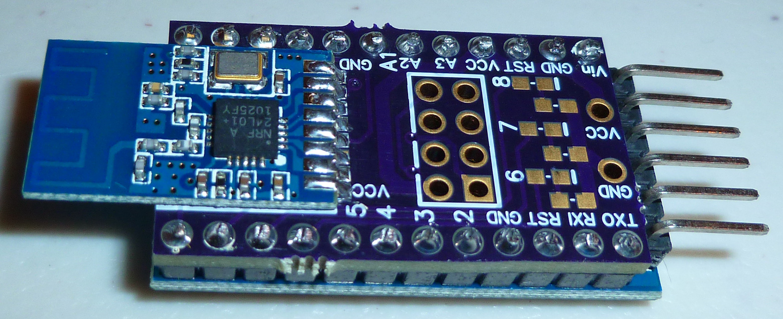

-
@NeverDie Neat! All I need is a rfm69 version

Where you get pcb?
-
@shabba said in What did you build today (Pictures) ?:
Where you get pcb?
https://www.openhardware.io/view/480/Compact-nRF24L01-Pro-Mini-Bottom-Shield
-
I just now put together the final test configuration:
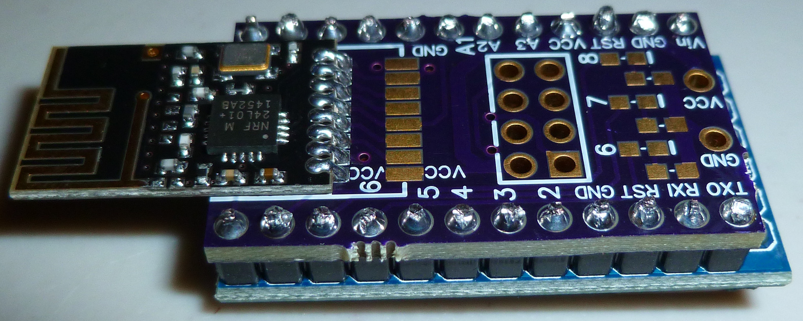
It's meant to be a "universal" shield that can accept any of the most common nRF24L01 modules, whether they be SMD or the 8-pin variety.
What I want people to know though is that as nice and compact as it is, it's actually much larger and not even as capable as the new nRF51 or nRF52 series. For instance, this nRF51 is quite affordable, and yet is both much smaller, is more energy efficient, and generally packs far more capability (including better range) than an atmega328p+nRF24L01 combo:
https://www.aliexpress.com/item/nRF51822-04-BLE4-0-Wireless-Bluetooth-Module-TTL-Low-Power-Consumption/32832511551.html?ws_ab_test=searchweb0_0&aff_platform=aaf&cpt=1509659805775&sk=rvbiMby&aff_trace_key=624250e1222041ebad3af56b86b62771-1509659805775-02431-rvbiMby&terminal_id=29bfb7ff18284b7f96acb3c3884390ce
The way I see it, there's not really much reason to continue using the nRF24L01's, except maybe already existing familiarity.[Edit: the one area that the nRF24L01's do still hold an edge, though, is in pricing on the PA+LNA versions. Some of those are still comparatively inexpensive compared to what's currently available in PA+LNA nRF5x series.
Luckily, the above shield will work with them too. ]
]
-
One advantage to the "atmega328p+nRF24L01 combo" is the simplicity of choices. A pro-mini is pretty much a pro-mini, etc. Having so many choices makes it hard for a beginner with nrf51.
I really appreciate the recommendation for a reasonably priced nrf51 that can be used for battery powered nodes. Can I also ask for a recommendation on a piece of hardware to program it? (Again, lots of choices).
Thanks ahead of time.
-
@ileneken3 said in What did you build today (Pictures) ?:
Can I also ask for a recommendation on a piece of hardware to program it?
I've tried/attempted a number of different ones, and I've settled on using the nRF52 DK as being the best for programming external modules (at least in my experience). Just be sure you power the modoule independently from the nRF52 DK, because the DK mostly senses the voltage on the module rather than powers it.
-
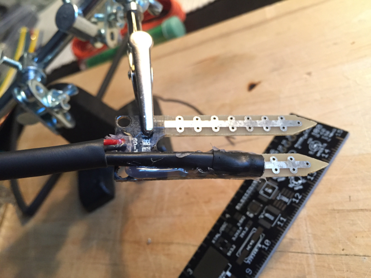
Protecting a ds18b20 tempersture sensor to measure soil temperature for a prototype node.
-
@mfalkvidd what is that in the background - some sort of PCB ruler?
-
Yes, I have one too. It has all the form factors of chips, wire gauges, etc
-
@mfalkvidd said in What did you build today (Pictures) ?:
Protecting a ds18b20 tempersture sensor
You may already know this, but it's easy to find ds18b20's that are enclosed in sealed metal probes. I've used some, and they don't seem to leak, even when left submerged in water.
-
Good ruler, I have such ruler too

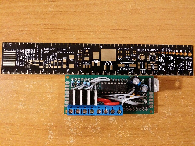
Today's power part of my RGBW dimmer node (four LED channel PWM inputs, 12V input, +12V sense, +5V, +3.3V outputs). Dimmer is controlled by MySensors and also by conventional Samsung TV remote control (five presets, ability to record color presets, autofade from one preset to another, control of each LED channel brightness, gamma correction and so on).
-
-
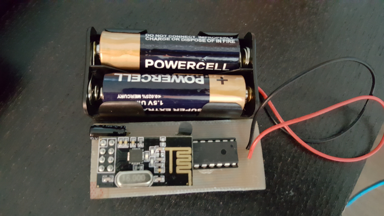
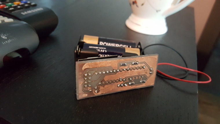
Just simple, small temperature node.
-
@scalpel
Nice. Waht kind of CNC machine did you use to make the PCB?
-
@NeverDie I would bet on chemicals instead cnc..
-
@scalz Yes. After looking at it more closely, I bet you're right.
-
Yes. Iron and B327 method

-
Does ferric chloride get used much any more?
-
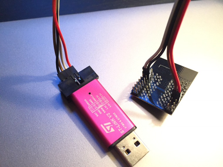
Today I finally got to work on the nrf51822 that I bought some months ago. Using the Arduino IDE and my st-link v2 clone I was able to flash a softdevice and load an example sketch.
It seems to have worked, but I don't know how to communicate with the device yet. Serial? Swd? Some app on my iphone? Will need to do some reading tomorrow. Recommendations are welcome.
-
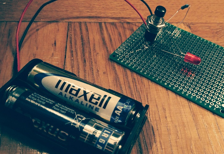
Today I introduced my 5 year old to soldering...
-
@sundberg84 said in What did you build today (Pictures) ?:
Today I introduced my 5 year old to soldering...
How did he like it?
-
@gohan it's fun to do projects together! We enjoyed it and I tried the water story to explain everything. Also some short instructions to solder the legs and not the solder itself... Now he is playing with it so a good result!
-
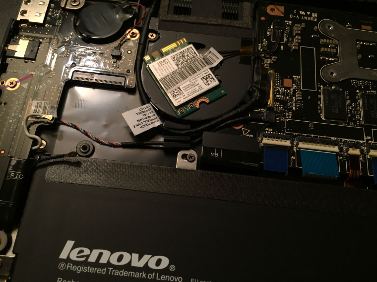
On the workbench today: My Lenovo laptop getting a wireless network card replacement.The old card was wonky. Sometimes it wouldn't allow any network activity for a minute or so. Sometimes it would allow traffic, but only at 1-2mbit. Sometimes, but very seldom, it would deliver the ~100mbit it was supposed to.
With the upgrade card (bought off Aliexpress of course
 ) it delivers 40 megabytes per second when copying files from my desktop, and has been able to sustain that speed for more than ten minutes straight so far (still testing). New life to my poor laptop!
-
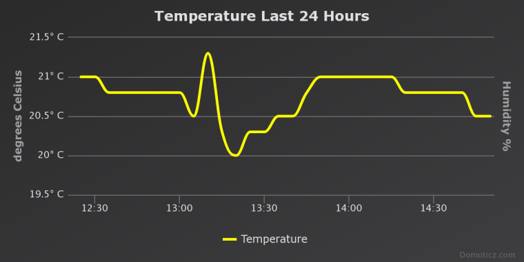
I soldered together a prototyhpe for a small wireless temperature sensor powered by a CR2032 button cell:
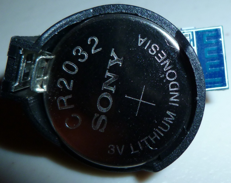
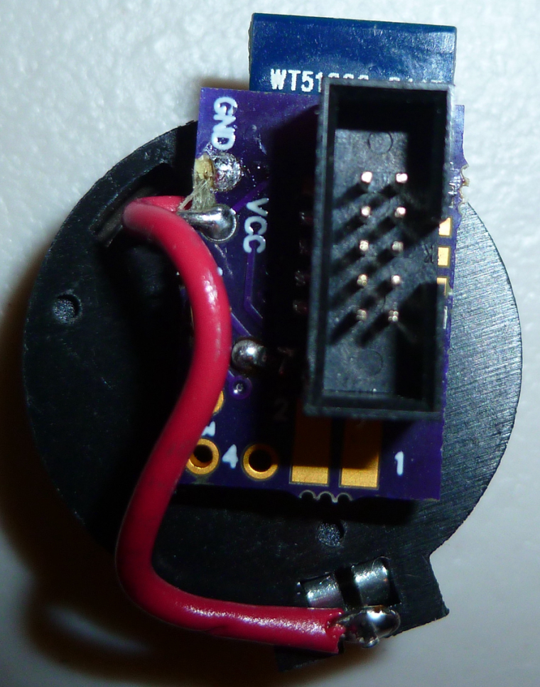
It works!
-
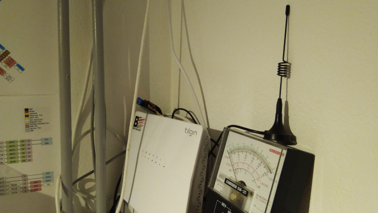
Today I'm doing some small things... Changed the antenna on my RFM gw to a bigger one. These one works really well!! Highly recommend.
-
I have one on the way already

-
The version 1 board for my button cell TH sensor finally arrived today. Though now obsolete compared to the current Version 4, I put it together anyway, and it works just fine.
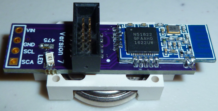
I'll be able to use the I2C connector to get the software working for the si7021 and BME280 TH boards, so I expect the firmware will be finalized and ready to install before the version 4 board even arrives.
-
Today's project:
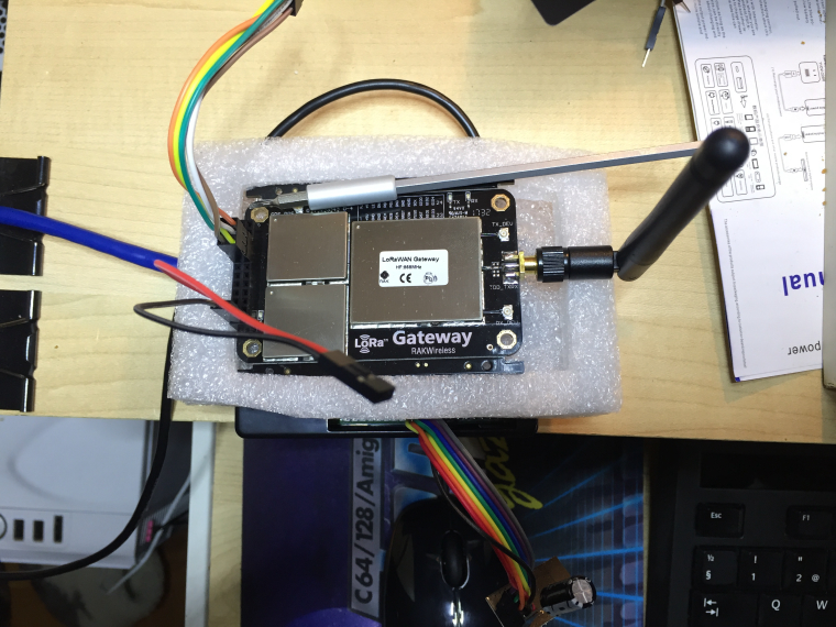
Time for the nrf24 to move over and my LoRa concentrator board to take its place on the lab RPi.
-
@mfalkvidd said in What did you build today (Pictures) ?:
Time for the nrf24 to move over and my LoRa concentrator board to take its place on the lab RPi.
Why?
-
@gohan a LoRaWAN gateway is more fun
-
@mfalkvidd
I envy your LoRaWAN gateway... so you will soon add this to TTN maps and show a new gateway in Sweden
-
@bjacobse define soon... it has already been connected to ttn for 2 hours

-
@mfalkvidd
Damn you're fast
-
Today I also started upgrading my Domoticz running Raspbian 7 (Wheezy) to Raspbian 9 (Stretch). I tried to do an in-place upgrade but the rpi wouldn't start after the upgrade so I had to start over on a clean Raspbian 9 image.
I took the chance to switch to f2fs for the root filesystem, which should make the SD card less susceptible to corruption. I used this guide and it worked, except that I also added discard to the fourth field in /etc/fstab and changed the sixth field to 0 to not fsck before boot.
When I wake up tomorrow, domoticz might have finished compiling.
-
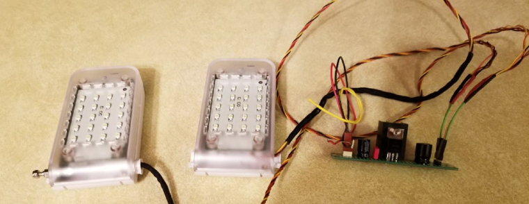
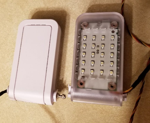
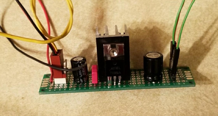
Though not directly MySensors related, I am setting my 3D printer up with some lights to see my prints for my MySensors projects better when running a job. These are some white LED light assemblies that have been salvaged from some recycled document cameras. I built a simple 7805 regulator circuit to run them. The next step is to design and print some brackets and articulating arms to mount them to the printer.
-
@mfalkvidd ai ai. Yes. I was warned on the Domoticz website about the 'not being able to startup'. I was able to successfully update from Wheezy to Jessi. Skipped the Stretch part for now.
Just made some preparations for the new node that has to replace several individual nodes in the technical-room. (Control of WTW, Measurement of heating pipes of CV using Temperature Sensors, Leakage Detector of CV, Door Sensor and last but not least OTGW-Reset)

Could not complete the PCB due to some missing components. The Sketch is running fine on my NANO
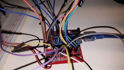
Looks like a mess now, but this development PCB comes in quite handy.
-
That was yesterday..

@tekka and I tested some new features he made, so here was my humble and fun test setup
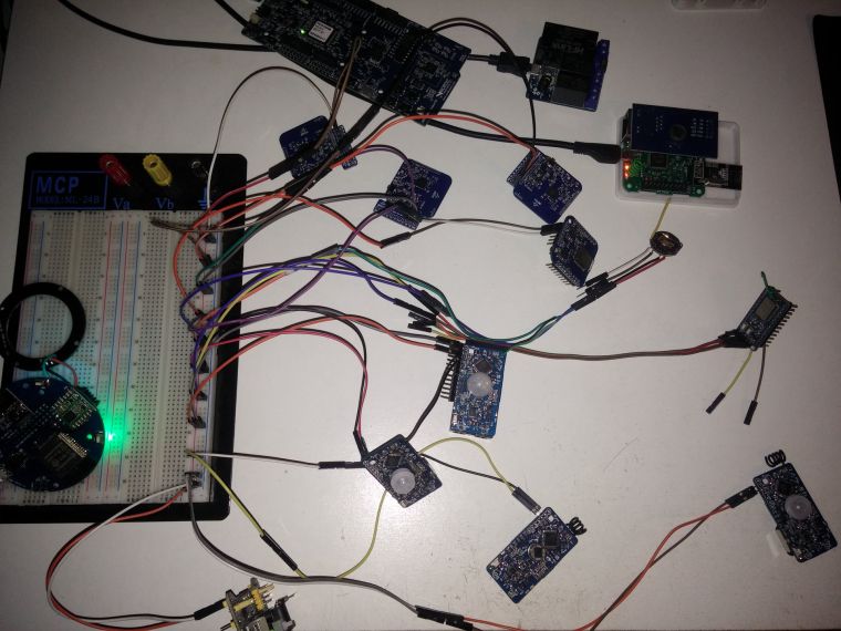
Of course the Halo GW didn't disappoint us! All boards (mixed mcus and radios nodes) were attacking it at an agressive rate (100ms rate), and there was no crash at all. Halo GW was laughing & kidding us saying "Please give me more, I like doing this"
 (but I was lazy to assemble more, there was 13 nodes on the table..).
Too strong @tekka
-
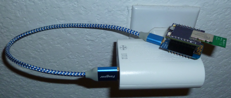
Here is my Wemos "Serial" wireless gateway that I just today put together and installed. Connects to Domoticz as an ethernet gateay over wi-fi. Uses a static IP address that I configured on the wi-fi router. By the way, it's powered (and physically supported) by an Ikea USB charger, as seen in the photo.

-
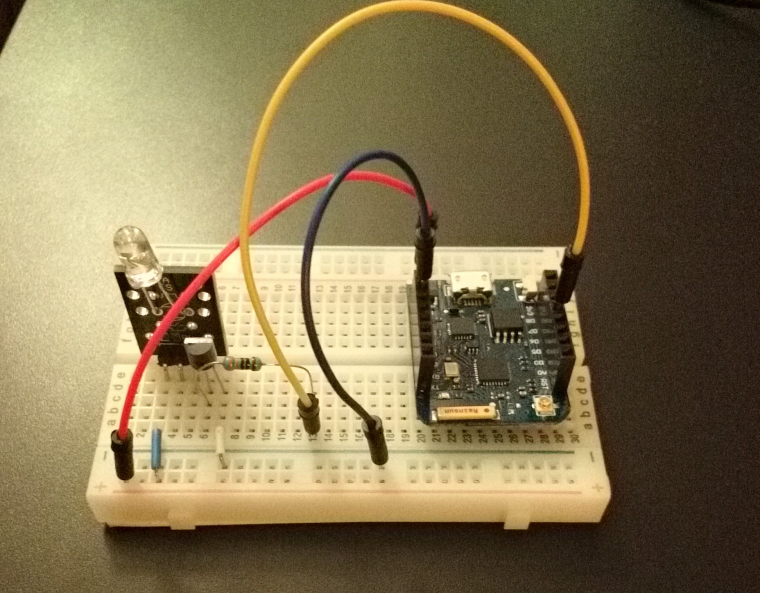
Mqtt IR remote controller for air conditioning / heat pump
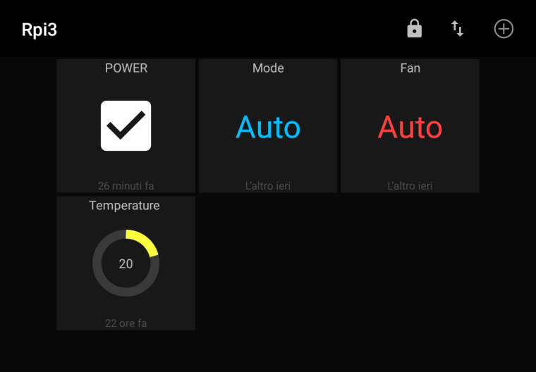
Quick interface design using Mqtt dash
Not mysensorized, but still a neat and cheap solution.
-
@gohan That would make for a very interesting project write-up, so that others might quickly replicate your work without a lot of head scratching.
-
It is actually very simple project: I followed this guide -> http://www.sysrun.io/2017/02/22/use-a-esp8266-to-control-your-ac-via-mqtt/ and used a pn2222a to boost the IR Led.
Also the app is very simple: just link each item to one of the topics.
It was meant to be a simple stand alone solution, connected to an external mqtt broker so you can turn on heating/cooling before coming back home without using any complex Home automation system. It is still in the test phase as I just have the IR led transmitting something and I have to test if it is actually working with the Daikin unit I need to control (it is not in my house so I have to way for the real test)
-
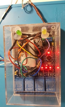
With help of @dbemowsk @sundberg84 I was able to complete my "CV All in one sensor" using the easy PCB.
It now replaces 2 Arduino Nanos with only 1 Easy PCB. Currently the 0,1u Capacitor is missing, however as I was told by the designer it still could work. And it does.This node:
- monitors the pipes of my central house heating,
- Is able to detect if the heating unit has a leakage.
- Switches on the light if the door is opened
- if the humidity in the bathroom becomes to high, or somebody is cooking.. It will start the BRINKS central WTW.
- Can reset my OTGW unit if it has a lock up.

-
4x cheap load cells under each foot of my bed
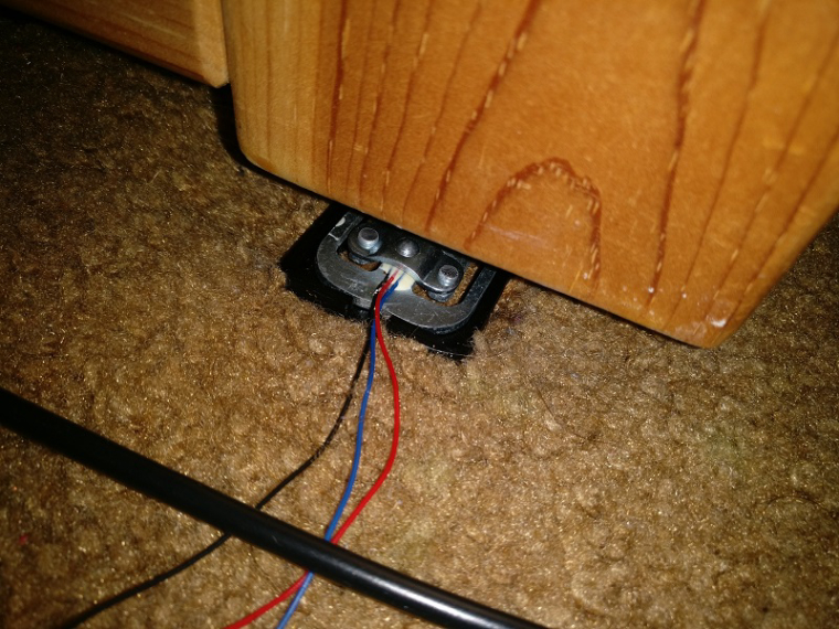
Sparkfun HX711 breakout and an Arduino
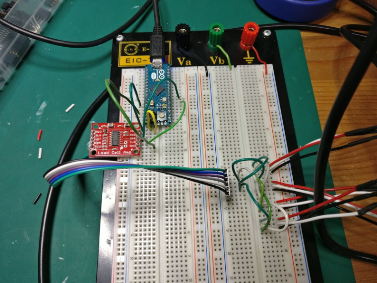
Was going for a bed occupancy sensor, but I got a pretty decent scale out of it, it is sensitive enough that it registers if I put my water bottle down on the bed.
-
@SquareKinematics said in What did you build today (Pictures) ?:
Was going for a bed occupancy sensor, but I got a pretty decent scale out of it, it is sensitive enough that it registers if I put my water bottle down on the bed.
Sounds awesome if it's that precise, could you make a post in "My Project" with reference to the load cells you used, wiring and some test code ? Thank you in advance

-
@Nca78 I will be sure to do that when it's done, it's still a little rough around the edges

-
Today I made a pogo pin programming board for my Logger. (The logger works except one last thing... Rev 5 here we come!)
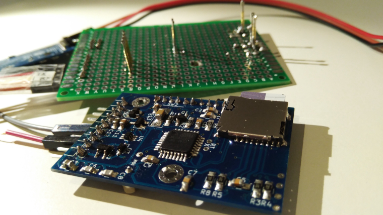
-
I've been playing with an Adafruit AudioFX board and cobbled together this annunciator. Eventually it will be a MySensors node to play alarms or other sounds. It is using a cheap portable speaker to play the sounds. I got it to work with my doorbell button node today.
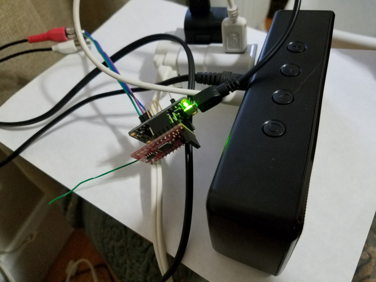
-
Last fix done on my Logger... I will send it to pcb house today and probably publish a beta on openhardware. Probably nothing special but for me as hobby pcb maker this has been a challenge and great knowledge increase in using oscilloscope and new components.
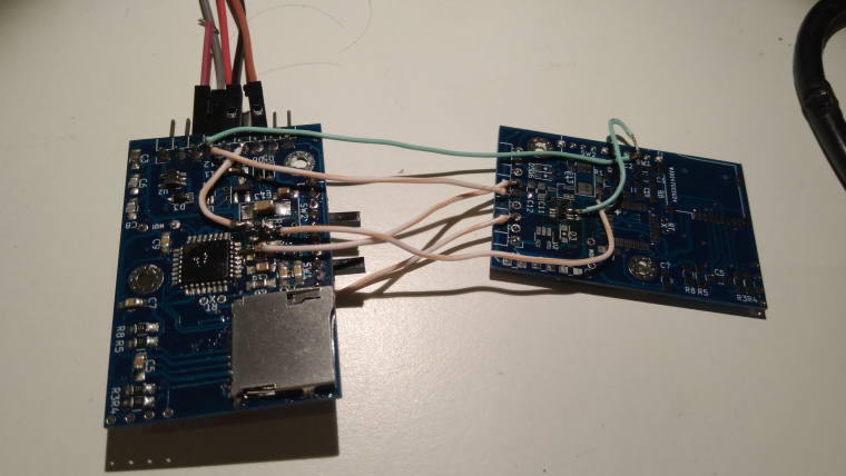
Tomorrow Black Friday!! (I work in retail so that's a high focus now...)
-
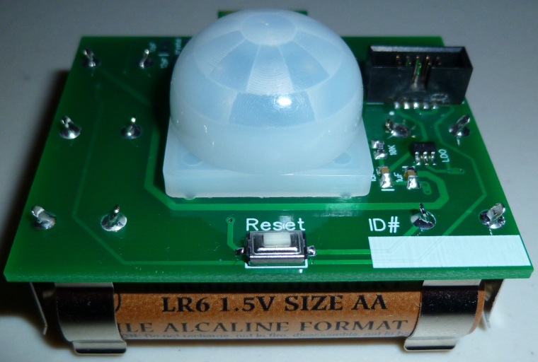
Yesterday received the PCB. Today assembled for testing this battery-powered nRF52-based passive infrared motion detector:
-
Battery powered MySensors Washing machine & dryer monitor, using LDR's to monitor LEDs on front of the appliances.
Each time a LED toggles, the node wakes from interrupt and sends a message. Easy peasy!
When a device is ready, I'll get a message on my mobile phone
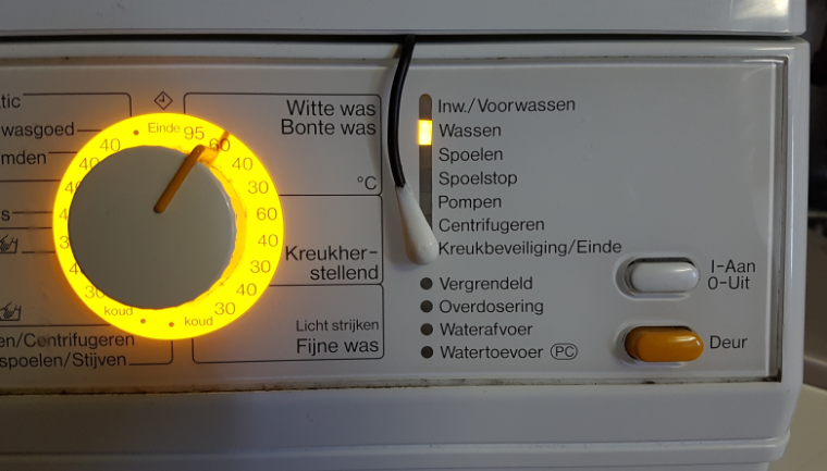
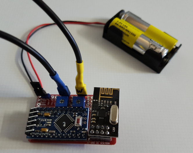
Still need to stuff it in an enclosure...
-
@Yveaux said in What did you build today (Pictures) ?:
Still need to stuff it in an enclosure...
Yes, definitely very low WAF

-
@gohan - you mean HIGH waf?
 I really like the design... (if the first picture is only what you see)
-
@sundberg84 said in What did you build today (Pictures) ?:
@gohan - you mean HIGH waf?
 I really like the design... (if the first picture is only what you see)
Ofcourse! WAF is overrated anyhow...
-
@Yveaux - Yes, as long as you don't tell her

-
@Yveaux
I think I have similar washing machine, doesn't the LED blink if leave the laundry inside the machine after it had ended washing?
Just curious, if you anyway have had the lid/cover removed from washing machine, why not solder wires parallel to LED and connect to an optocoupler that feeds signal direct to Arduino, and also take 5V supply from the washing machine, and then you can avoid using batteries
-
@bjacobse it's pretty different to remove the top that's usually easily removable to put inside furniture, and to unmount front panel and then solder stuff on the PCB. High WAF probably includes ensuring the warranty is not void

-
@bjacobse said in What did you build today (Pictures) ?:
@Yveaux
I think I have similar washing machine, doesn't the LED blink if leave the laundry inside the machine after it had ended washing?The sensor is placed on a led that lights when the machine is finished. I would prefer a led that is lit when it is washing and goes out when finished, but my machine hasn't any.
Just curious, if you anyway have had the lid/cover removed from washing machine, why not solder wires parallel to LED and connect to an optocoupler that feeds signal direct to Arduino, and also take 5V supply from the washing machine, and then you can avoid using batteries
Now I simply removed the cover to hide the wire. The electronics and led are hidden behind a lot of metal aan plastic. I didn't want to take the washer apart and the dryer too.
Just a simple solution working for multiple devices.
-
@Yveaux said in What did you build today (Pictures) ?:
@bjacobse said in What did you build today (Pictures) ?:
@Yveaux
I think I have similar washing machine, doesn't the LED blink if leave the laundry inside the machine after it had ended washing?The sensor is placed on a led that lights when the machine is finished. I would prefer a led that is lit when it is washing and goes out when finished, but my machine hasn't any.
Just curious, if you anyway have had the lid/cover removed from washing machine, why not solder wires parallel to LED and connect to an optocoupler that feeds signal direct to Arduino, and also take 5V supply from the washing machine, and then you can avoid using batteries
Now I simply removed the cover to hide the wire. The electronics and led are hidden behind a lot of metal aan plastic. I didn't want to take the washer apart and the dryer too.
Just a simple solution working for multiple devices.
Ah this make good sense, I didn't think the electronics was hidden and difficult to get to
-
@bjacobse said in What did you build today (Pictures) ?:
Ah this make good sense, I didn't think the electronics was hidden and difficult to get to
It's German quality

-
Finally got my LoRaWAN RAk831 with RPI gateway online
-
@Yveaux So I never fully understood the reasoning behind putting sensors on a washer or dryer. So you start your clothes washing or drying before you leave for somewhere. Is there a reason to know that it's finished when you are away? There is nothing you can do about it until you get home, at which time you could reasonably assume that it is finished. If you are home, can't you just go and check it after some time? Why would you need a message on your phone?
Just curious.
-
@dbemowsk just to keep the machines running continuously

And I need to go up 3 stairs to just check on them
-
@Yveaux Makes some sense. Another reason would probably be....."Because you can"... LOL
-
@dbemowsk said in What did you build today (Pictures) ?:
@Yveaux So I never fully understood the reasoning behind putting sensors on a washer or dryer. So you start your clothes washing or drying before you leave for somewhere. Is there a reason to know that it's finished when you are away? There is nothing you can do about it until you get home, at which time you could reasonably assume that it is finished. If you are home, can't you just go and check it after some time? Why would you need a message on your phone?
Just curious.
Or if someone else than you starts the machine before leaving for the full day, and you come back much earlier and if you don't have a warning you don't necessarily think about checking the washing machine when you arrive home. Here with the warm temperature if I leave the laundry in the washing machine for 4-5 hours without opening, I'm good for a new wash because it will smell pretty bad

-
@dbemowsk
My wife actually fairly often forget to check when the washingmachine is finished, and notice it a few hours later, when kids are a sleep and there is quiet in the house, I will imagine receiving an SMS when washing machine is ready to be emptied will help her, as she is checking her phone often,, even when kids are using all her time