Navigation

    • Register
    • Login
    • OpenHardware.io
    • Categories
    • Recent
    • Tags
    • Popular
    1. Home
    2. korttoma
    3. Best
    • Profile
    • Following
    • Followers
    • Topics
    • Posts
    • Best
    • Groups

    Best posts made by korttoma

    • RE: πŸ’¬ Dimmable LED Actuator

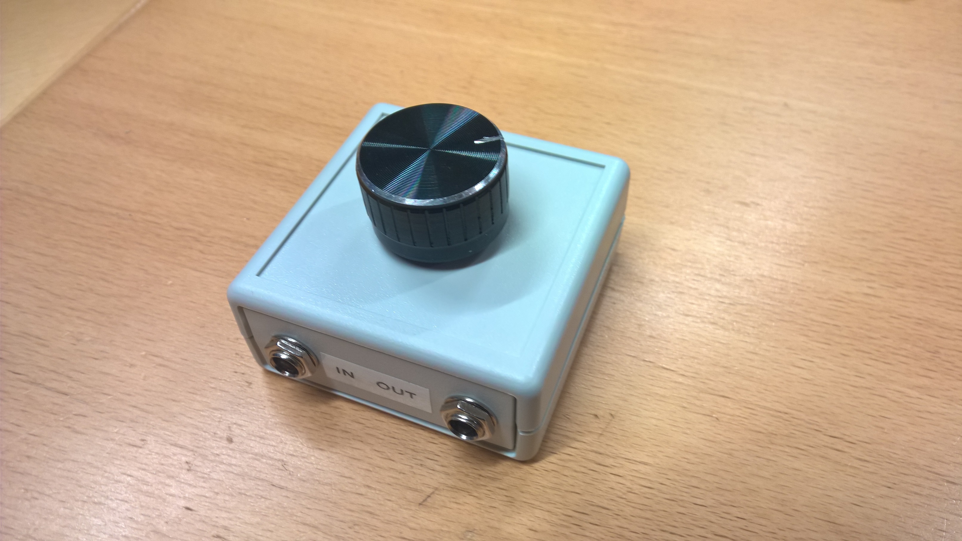
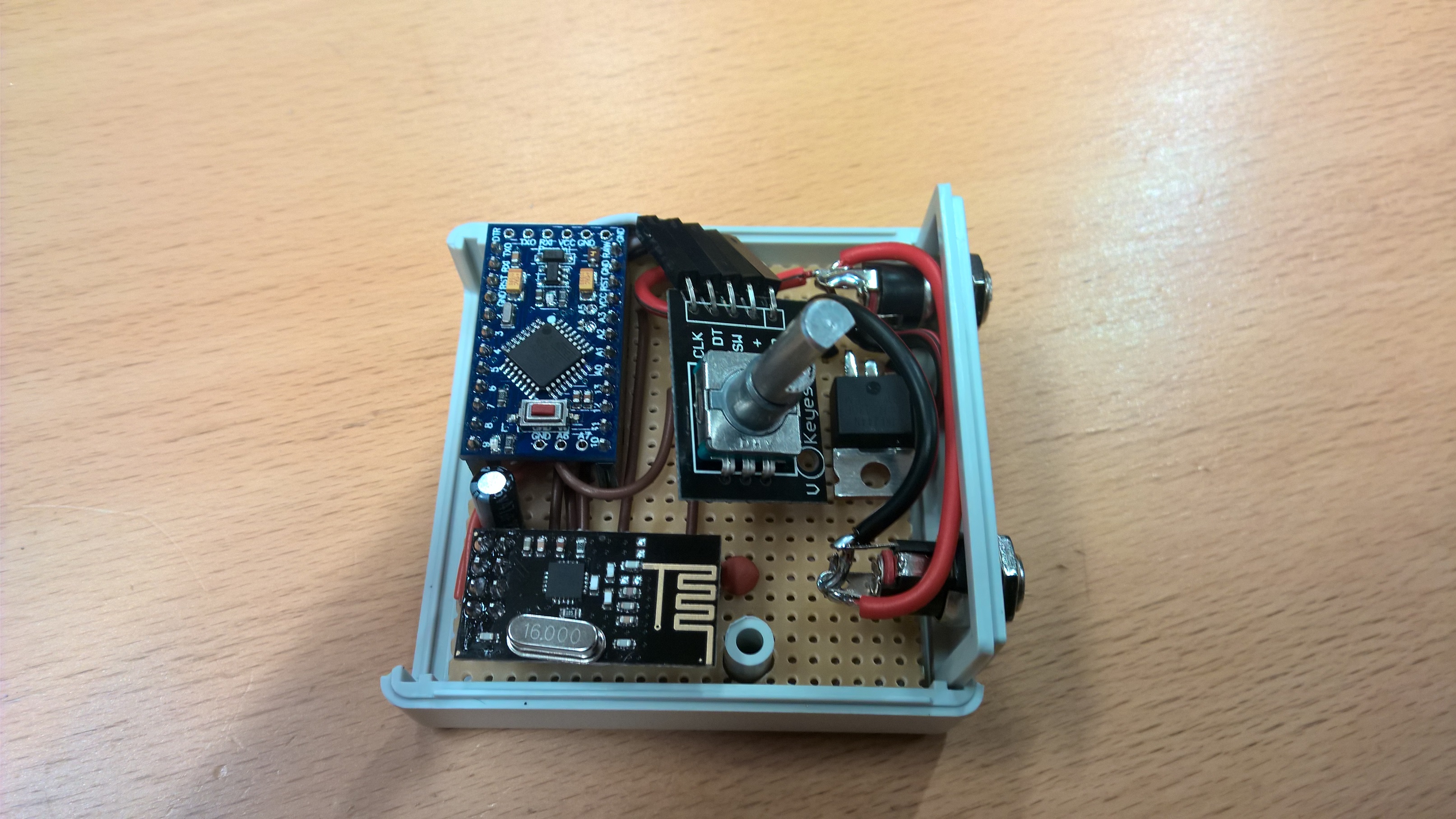
      Inspirational pictures from my Dimmable LED Actuator with rotary encoder device I made for my sons bedside lamp.
      Running this at 12VDC. His lamp had a G9 socket so I just broke apart the G9 LED bulb and soldered some G4 12VDC LED lights like these to it and replaces the "Dumb" switch with a 5mm DC plug. It turned out so nice that I think I will MySensor my own bedside lamp also.

      Edit: btw, I found the nice big knobs from here -> eBay

      0_1476680417320_WP_20161014_07_07_53.jpg

      0_1476680429390_WP_20161014_07_11_47.jpg

      posted in Announcements
      korttoma
      korttoma
    • MySensored 230v motion sensor with light level

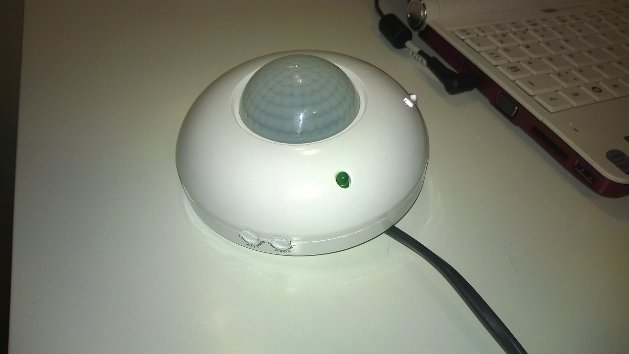
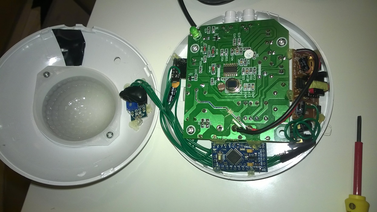
      I have been searching for a nice enclosure to use with some motion sensors but nothing was to my satisfactory. So I started to look at different motion sensors to see if I could find something I could modify. I found this one at my local electronics shop. Both looks and prize was right so I picked one up.

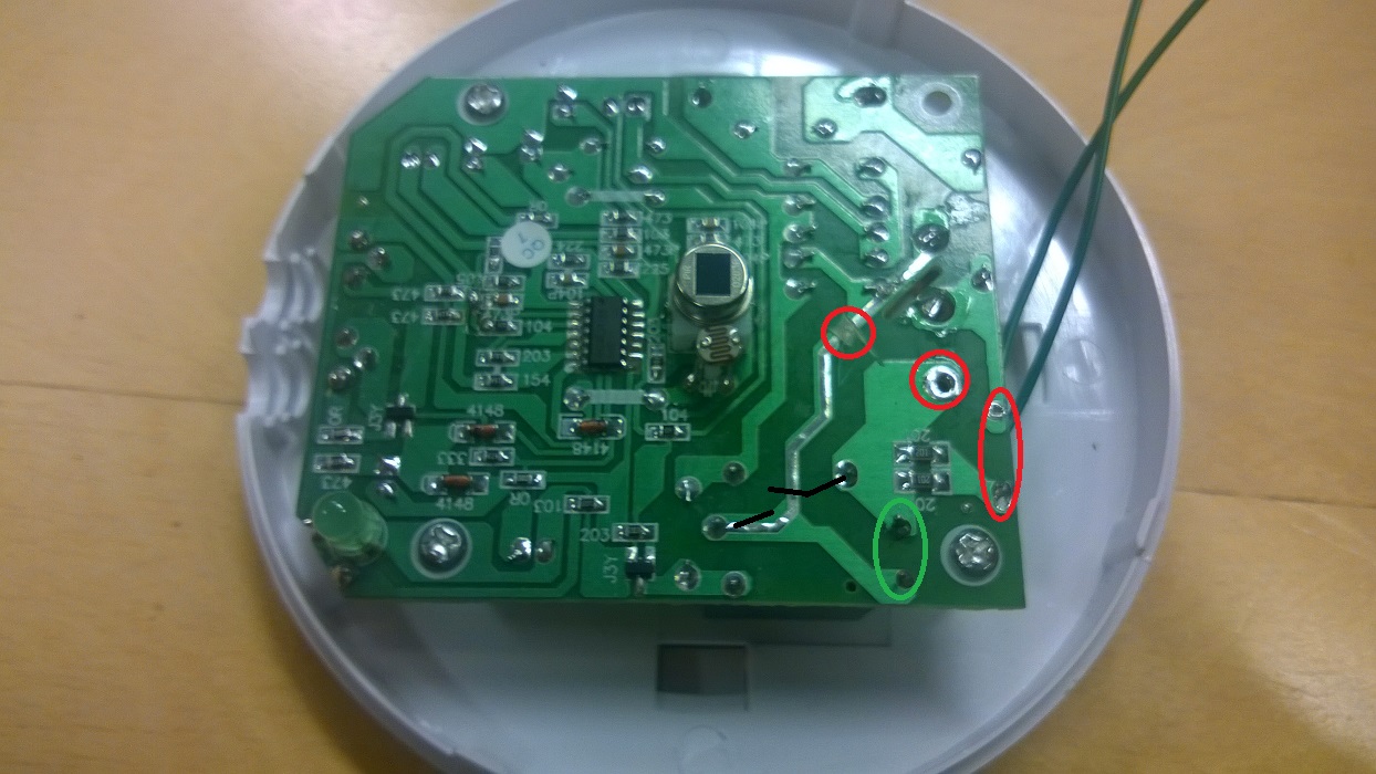
      I cut the Live copper strip to the relay and removed the wire that would normally go to the lamp and removed 2 capacitors (marked with red and green), soldered 2 wires to were a capacitor had been to access the relay contacts (marked with green).
      WP_20141126_001.jpg

      Destroid one of them 90 cent iPhone charger clones to get a 5v power supply added a Pro Mini with radio and a LM393 photo resistor.
      Connected the relay contacts to GND and a binary in on the arduino and the photo transistor to a analog in.
      WP_20141126_003.jpg

      Here is the result:
      WP_20141126_006.jpg

      And here is the sketch:
      https://codebender.cc/sketch:62574

      Have not attached it to the ceiling yet just had it on the floor for testing, motion sensor works great but I'm not sure if the light sensor will be sensitive enough.

      Think I'm going to add a 2A glas fuse to it because of the cheep 5v power just in case.

      posted in My Project
      korttoma
      korttoma
    • RE: Temperature sensor accuracy comparison

      @wes Thanks for the list of sensor accuracy. But for for example battery nodes there are other parameters that are at least as important as temp accuracy and you left out the Si7021 that is really good for battery driven nodes.

      Si7021
      Precision Relative Humidity Sensor Β± 3% RH (max), 0–80% RH
      High Accuracy Temperature Sensor Β±0.4 Β°C (max), –10 to 85 Β°C
      Wide operating voltage (1.9 to 3.6 V)
      Low Power Consumption 150 Β΅A active current 60 nA standby current

      posted in Hardware
      korttoma
      korttoma
    • RE: First run of new nodeMCU based GatewaySerial. Not sure what it is saying.

      The correct way to use any ESP8266 based boards with the current MySensors implementation is to configure them as WiFi Gateways with local sensors. You cannot make one ESP8266 an serial GW and expect all other ESPs to communicate via this one using the WiFi.

      I other words all your ESPs will be Gateways but without any transport (NRF24L01 or RFM69 that is currently supported).

      posted in Troubleshooting
      korttoma
      korttoma
    • RE: nRF5 action!

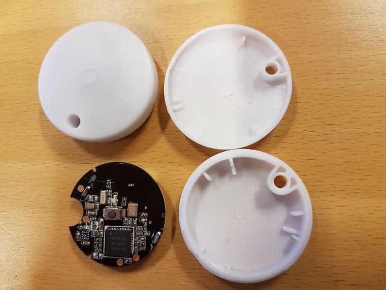
      @nca78 I have now measured the current consumption of the small bluetooth beacon device (N51822 QFABC0) using your code and the results are encouraging.

      With your code I get around 4uA sleep current compared to 800-4000uA with my old code πŸ˜„

      Measurements done with an Micro (nano) ampere meter (double) that has not been calibrated against a reliable meter so do not take the measured values so seriously but more as a comparison.

      Device

      posted in My Project
      korttoma
      korttoma
    • RE: πŸ’¬ Building a WiFi Gateway using ESP8266

      @sghazagh maybe you can take a picture of the setup. Maybe someone else can see something that you don't.

      posted in Announcements
      korttoma
      korttoma
    • RE: Relay with button

      @Lanman said:

      doesn't seem to work

      Can you elaborate on this? What is it that is not working? Can you get the serial debug output from your node?

      // Enable debug prints
      #define MY_DEBUG
      
      posted in Troubleshooting
      korttoma
      korttoma
    • Alternative battery operated motion sensor using 433MHz sensors

      I never managed to get a motion sensor attached to an arduino to work reliably, especially on batteries so I looked for an alternative using ready made sensor that could be "MySensord". Here is what I came up with:

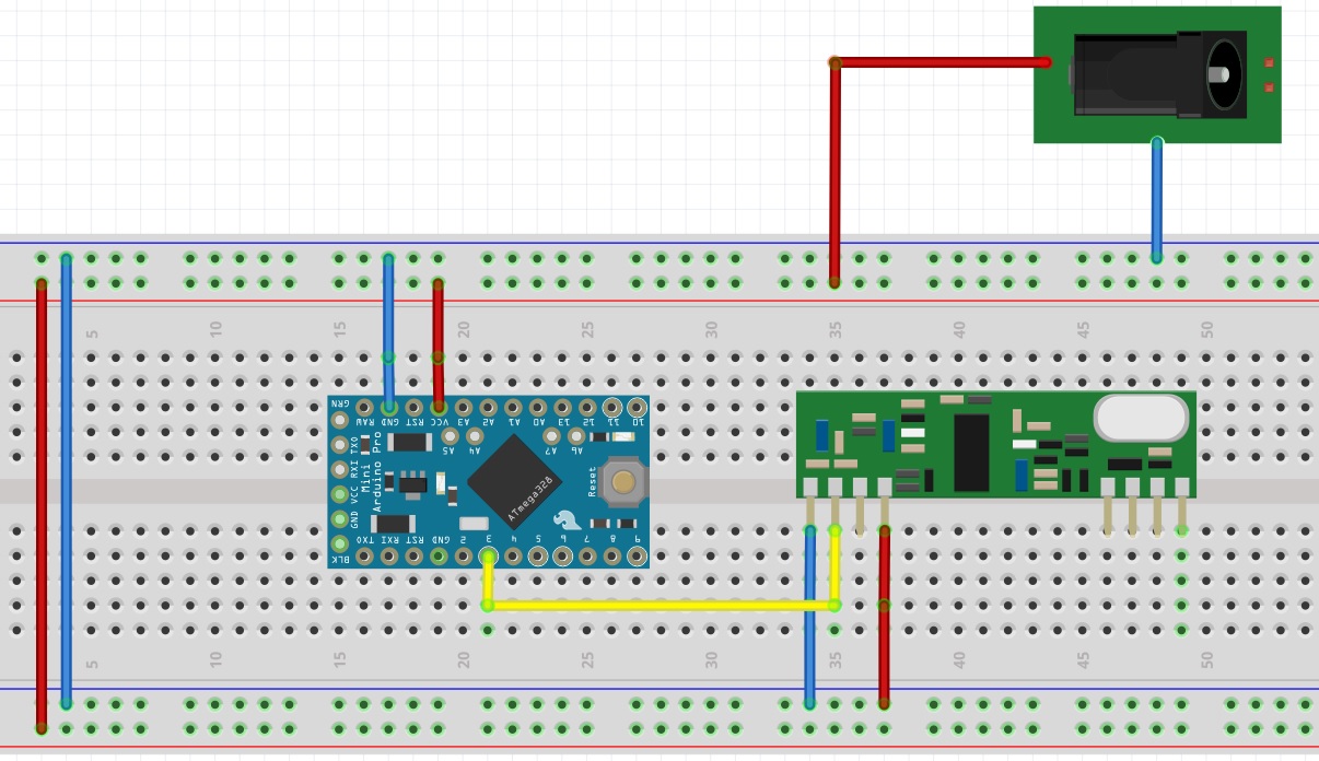
      I found these 433MHz battery operated Motion sensors that seemed like a nice alternative and then I got myself this 433MHz receiver to hock up to my MySensors 5V Pro Mini node like this (I allso connected an NRF24L01+ but I left it out from the drawing to keep it clean):

      0_1479892250747_433MHzReceiver.jpg

      I attached a 17,3cm wire as a quarter length antenna to the receiver calculated here

      Then I created this sketch to handle it all:

      /**
       * The MySensors Arduino library handles the wireless radio link and protocol
       * between your home built sensors/actuators and HA controller of choice.
       * The sensors forms a self healing radio network with optional repeaters. Each
       * repeater and gateway builds a routing tables in EEPROM which keeps track of the
       * network topology allowing messages to be routed to nodes.
       *
       * Created by Henrik Ekblad <henrik.ekblad@mysensors.org>
       * Copyright (C) 2013-2015 Sensnology AB
       * Full contributor list: https://github.com/mysensors/Arduino/graphs/contributors
       *
       * Documentation: http://www.mysensors.org
       * Support Forum: http://forum.mysensors.org
       *
       * This program is free software; you can redistribute it and/or
       * modify it under the terms of the GNU General Public License
       * version 2 as published by the Free Software Foundation.
       *
       *******************************
       *
       *
       *
       *
       */
      
      // Enable debug prints
      //#define MY_DEBUG
      
      // Enable and select radio type attached
      #define MY_RADIO_NRF24
      //#define MY_RADIO_RFM69
      #define MY_BAUD_RATE  9600
      
      #define MY_NODE_ID 18
      #define SKETCH_NAME "RF433 Motion"
      #define SKETCH_VERSION "1.0"
      
      #include <MySensors.h>
      #include <RCSwitch.h>
      #include <SPI.h>
      
      unsigned long TRIP_RESET_TIME = 120000;
      
      unsigned long NOW_TIME = millis();
      unsigned long KnownSensor1 = 5945054;
      unsigned long TRIP_TIME_1 = millis();
      bool untripsent_1 = 1;
      bool tripped_1 = 0;
      
      unsigned long KnownSensor2 = 5914846;
      unsigned long TRIP_TIME_2 = millis();
      bool untripsent_2 = 1;
      bool tripped_2 = 0;
      
      #define RF433RECIEVER 3   // The digital input you attached your motion sensor.  (Only 2 and 3 generates interrupt!)
      
      RCSwitch mySwitch = RCSwitch();
      
      #define CHILD_ID_1 1   // Id of the sensor child
      #define CHILD_ID_2 2   // Id of the sensor child
      
      // Initialize motion message
      MyMessage msg1(CHILD_ID_1, V_TRIPPED);
      MyMessage msg2(CHILD_ID_2, V_TRIPPED);
      
      void setup()
      {
        mySwitch.enableReceive(digitalPinToInterrupt(RF433RECIEVER));  // Receiver on interrupt 0 => that is pin #2
      
      }
      
      void presentation()  {
        // Send the sketch version information to the gateway and Controller
        sendSketchInfo(SKETCH_NAME, SKETCH_VERSION);
      
        wait(50);
        // Register all sensors to gw (they will be created as child devices)
        present(CHILD_ID_1, S_MOTION);
        wait(50);
        present(CHILD_ID_2, S_MOTION);
        wait(50);
      
      }
      
      void loop()
      {
      
      
        if (mySwitch.available()) {
      
          int value = mySwitch.getReceivedValue();
      
          if (value == 0) {
            Serial.print("Unknown encoding");
          } else {
            Serial.print("Received ");
            Serial.println( mySwitch.getReceivedValue() );
            //Serial.print(" / ");
            //Serial.print( mySwitch.getReceivedBitlength() );
            //Serial.print("bit ");
            //Serial.println( mySwitch.getReceivedProtocol() );
      
            if (mySwitch.getReceivedValue() == KnownSensor1) {
              int value = mySwitch.getReceivedValue();
      
              if (tripped_1 == 0) {
                Serial.println("Sending Tripped value");
                send(msg1.set(1));  // Send tripped value to gw
                tripped_1 = 1;
              }
      
              TRIP_TIME_1 = millis();
              untripsent_1 = 0;    
            }
      
            if (mySwitch.getReceivedValue() == KnownSensor2) {
              int value = mySwitch.getReceivedValue();
      
              if (tripped_2 == 0) {
                Serial.println("Sending Tripped value");
                send(msg2.set(1));  // Send tripped value to gw
                tripped_2 = 1;
              }
      
              TRIP_TIME_2 = millis();
              untripsent_2 = 0;        
            }
      
            mySwitch.resetAvailable();
          }
      
        }
        
        unsigned long NOW_TIME = millis();
        
        if ((NOW_TIME - TRIP_TIME_1 >= TRIP_RESET_TIME) && (untripsent_1 == 0))
        {
          Serial.println("Sending Un-tripped value");
          send(msg1.set(0));  // Send Un-tripped value to gw
          TRIP_TIME_1 = NOW_TIME;
          untripsent_1 = 1;
          tripped_1 = 0;
        }
      
        if ((NOW_TIME - TRIP_TIME_2 >= TRIP_RESET_TIME) && (untripsent_2 == 0))
        {
          Serial.println("Sending Un-tripped value");
          send(msg2.set(0));  // Send Un-tripped value to gw
          TRIP_TIME_2 = NOW_TIME;
          untripsent_2 = 1;
          tripped_2 = 0;    
        }
        
      }


      So far I'm happy with the performance. I have one outside sending me a snapshot from a camera if there is movement when we are away and I have not had any false triggers so far. The communication range of the 433MHz sensors is great. I cannot comment on how long the batteries will hold on these since they have only been in use a few weeks.

      posted in My Project
      korttoma
      korttoma
    • RE: Request: New Sensor Type ? Thermostatically controlled switch

      I finally put together a thermostat device sketch. Unfortunately it got a bit out of hand and I implemented lots of features that most people probably not need.

      Not sure if I'm using the V_HVAC_FLOW_STATE and V_HVAC_SETPOINT_HEAT correctly but it seems to work with my Vera UI5 presented as a S_HEATER device.

      Here is the sketch in case someone needs it.

      https://codebender.cc/sketch:169733

      posted in Feature Requests
      korttoma
      korttoma
    • RE: πŸ’¬ Easy/Newbie PCB for MySensors

      @maghac it is not just as simple as the capacitor size is added, true it is added but different size capacitors also filter disturbances at different frequencies. So adding different size capacitors in parallel can act as a more effective disturbance filter.

      posted in OpenHardware.io
      korttoma
      korttoma
    • RE: Relay with button

      @Lanman said:

      Multiple libraries were found for "MySensors.h"
      Used: D:\Data\Documents\Arduino\libraries\MySensors
      Not used: C:\Program Files (x86)\Arduino\libraries\MySensors-master

      Looks like you just have some issues with your libraries.

      Seems like you have 2 instances of the MySensors library installed in 2 different locations. Maybe you should delete or move the one you are not using to another location.

      Also the Bounce2 library is not included in the MySensors 2.0 library so you need to install it separately if it is missing.
      You can collect the Bounce2 library from this collection -> https://github.com/mysensors/MySensorsArduinoExamples

      posted in Troubleshooting
      korttoma
      korttoma
    • RE: nRF5 action!

      Just received these tiny NRF51822 devices and would like to turn them in to MySensors 1 button scencontroller.
      Where should I start?

      1. I guess I will need some kind of USB adapter ti program them. Think I read somewhere about JLink. Would this do?

      0_1515562170867_20180110_071948.jpg

      posted in My Project
      korttoma
      korttoma
    • RE: Ethernet gateaway with wemos D1 (ESP8266)

      It should be possible to create a WiFi ESP8266 Gateway using the WeMos D1.

      Start from here -> https://www.mysensors.org/build/esp8266_gateway

      Seems like the pinout of the NodeMCU is similar to the WeMos but to be sure you could check from here -> https://www.wemos.cc/product/d1-mini-pro.html

      Hope this helps

      posted in Feature Requests
      korttoma
      korttoma
    • RE: Scene Controller

      @naveen said:

      @korttoma , what's yours like??

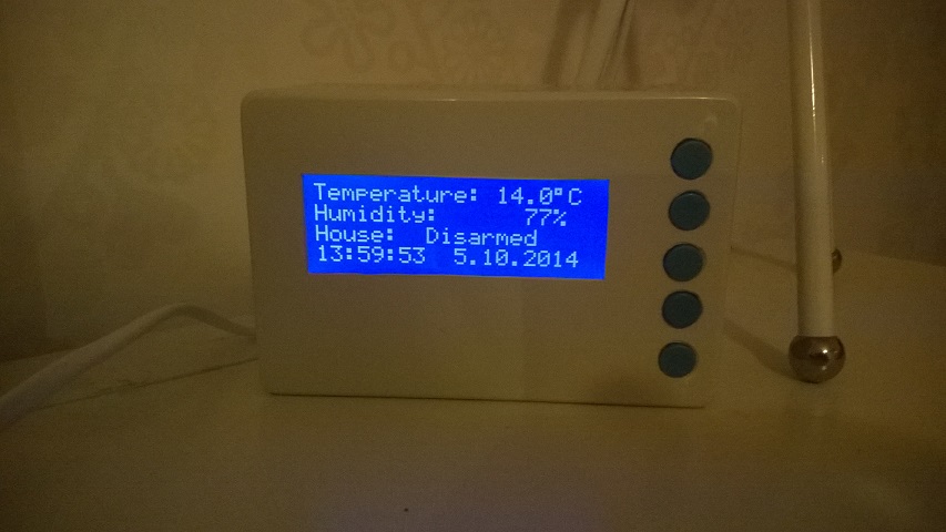
      WP_20141005_005.jpg

      The picture is a little dark but you get the idea. White box with blue buttons.

      posted in Development
      korttoma
      korttoma
    • RE: Only ethernet nodes?

      You can connect sensors directly to the Gateway and you can connect several Gateways to your Controller ( You need to check if Domoticz can handle this ).

      So what you will have is several of these:
      Sensor <-> GatewayNode <--wired--> Controller

      posted in General Discussion
      korttoma
      korttoma
    • RE: "Last update" node field in Vera interface

      @hek tested to replace '%H:%M' with '%c' and it gave a quite nice result:

      0_1485157093862_procent_c.jpg

      posted in Vera
      korttoma
      korttoma
    • RE: Newbie Problem! Get Started with NRF24L01+

      Don't use 0 for your node ID! (gw.begin(NULL, 0);) Choose a value beween 1 and 254.

      nodeId - The unique id (1-254) for this sensor.
      

      Do not confuse this with child sensor ID

      childSensorId - The unique child id you want to choose for the sensor connected to this Arduino. Range 0-254.
      posted in Development
      korttoma
      korttoma
    • RE: 2.0 gateway with 1.5 sensors [SOLVED]

      Yes, you need to first update the gateway to 2.0. Most 1.5.4 sensors should work with 2.0 Gateway. But 2.0 Sensors will not work with old Gateway. I had no issues with my sensors during the couple of weeks I updated them. There might of course be exceptions to this.

      posted in General Discussion
      korttoma
      korttoma
    • RE: 2 or more DHT22 - Sensors on one Arduino pro mini

      Here are the instructions how to convert the sketch. Please try and if you run in to trouble please let me know and I will walk you through it.

      Converting sketch from 1.5 to to 2.0

      Add the following to activate NRF-radio support

      #define MY_RADIO_NRF24
      

      Remove MySensor constructor

      MySensors gw;
      

      Remove MySensors setup() call

      gw.setup(....);
      

      If node expects incoming messages, add the following function to handle data:
      void receive(const MyMessage &msg) {}

      Move present() and sendSketchInfo() from setup() to a new function called presentation().

      void presentation() {
           sendSketchInfo(...)	
           present(...);
      }
      

      If you’re using static ids , add:

      #define MY_NODE_ID xx
      

      If static parent node is used, add:

      #define MY_PARENT_NODE_ID xx
      

      If you want node to be a repeater, add

      #define MY_REPEATER_FEATURE
      

      If you need to reconfigure your CE/CS Pins (not needed if NRF is connected to default pins)

      #define MY_RF24_CE_PIN 9
      #define MY_RF24_CS_PIN 10
      

      Remove all β€œgw.” before MySensors library calls.

      If node requests time using requestTime(), remove callback argument define define the following function to handle time response:

      void receiveTime(unsigned long ts) {
      }
      

      Make sure to include MySensors.h after any configuration defines.
      posted in Development
      korttoma
      korttoma
    • Synthetic Sensors

      How cool isn't this πŸ˜„ -> https://www.youtube.com/watch?v=aqbKrrru2co

      http://www.gierad.com/projects/supersensor/

      posted in General Discussion
      korttoma
      korttoma
    • RE: Programming needed to enable RFM69 radio with 5100 ethernet code.

      The example sketch included in the MySensors library should work just fine if you enable the correct radio and define the frequenzy to be used and radio hardware type if it is HW like this:

      #define MY_RADIO_RFM69
      #define MY_RFM69_FREQUENCY RF69_433MHZ
      #define MY_IS_RFM69HW
      
      posted in Development
      korttoma
      korttoma
    • RE: S_HVAC device on vera doesnt set set point to arduino

      finally managed to work out the GitHub part, I had to update the desktop software and remove the 2 year old project I had there, I stil find it quite confusing.

      posted in Bug Reports
      korttoma
      korttoma
    • RE: πŸ’¬ Soil Moisture Sensor

      @alowhum Thanks for the info. I have one of these and I would like to somehow integrate it with my other sensors. Maybe it would be possible to build a MySensors Bluetooth GW node to connect to the Mi Flora.

      posted in Announcements
      korttoma
      korttoma
    • RE: Energy Harvesting

      Not sure what kind of application you had in mind but there is always the peltier element if you have something hot and a possibility to cool it on the other side. Tons of them on ebay.

      Or why not a stirling generator πŸ˜„ -> http://www.instructables.com/id/Tin-Can-Stirling-Engine/

      posted in General Discussion
      korttoma
      korttoma
    • RE: Scene Controller

      Sweet! Now I don't feel like pasting any pictures of my scene controller anymore.

      posted in Development
      korttoma
      korttoma
    • RE: [solved] RFM69 based nodes unable to report Lib Version

      @scalz said:

      @korttoma
      i'm working on rfm69 so i put this on my list πŸ˜‰

      If you get to the point where you have something that could be tested please feel free to let me know.
      I have a small setup that I use for testing so I could possibly help with testing even if I have limited hardware.

      posted in Bug Reports
      korttoma
      korttoma
    • RE: πŸ’¬ Dimmable LED Actuator

      @Laces yes you can. The principal is the same, just one mosfet per channel.
      Search the forum for RGB or RGBW and you sould be able to find some examples.

      posted in Announcements
      korttoma
      korttoma
    • RE: Hacking a Neato Robotics BotVac Connected

      FYI, a friend of mine has created a PHP library for the Neato cloud service -> https://github.com/tomrosenback/botvac

      It is based on the work @kangguru has done.

      posted in General Discussion
      korttoma
      korttoma
    • RE: Scene Controller

      @BulldogLowell said:

      nice job thomas!

      Thanks Jim, btw I figured out a neet way to dim the backlight using just a resistor and a transistor. On the I2C LCD driver board there is a jumper for the backlight and I just connected the transistor to these 2 pins and the gate via a 10kR to a PWM pin. Works great.

      Also I want to thank you Jim again cause I started from your weather station scene controller and ended up with this:

      https://codebender.cc/sketch:44676

      posted in Development
      korttoma
      korttoma
    • RE: [solved] RFM69 based nodes unable to report Lib Version

      tried the latest development branch on my test system and the results are good so far. Now I just need to update my "real" system also. Thanks to everyone that participated in solving this!!

      posted in Bug Reports
      korttoma
      korttoma
    • RE: πŸ’¬ ESP-LINK ESP8266 WeMos D1 Mini Adapter Board

      I think I found the problem. I think it misbehaved because of an illegal character in the "HOSTNAME". Changed the hostname yesterday and It was still alive this morning even if I have not pinged it.

      posted in OpenHardware.io
      korttoma
      korttoma
    • RE: Merge Sketches

      Have you seen the video collection here -> http://www.mysensors.org/about/videos

      There is one called "Combining MySensors example sketches" maybe it can be helpful for you.

      posted in General Discussion
      korttoma
      korttoma
    • RE: implementing multiple sensors

      Or here is an example I'm using:

      https://codebender.cc/sketch:44740

      posted in Development
      korttoma
      korttoma
    • RE: [solved] RFM69 based nodes unable to report Lib Version

      Updated now also 2 nodes in my "real" system and both now successfully reported Lib version. I did not update the GW. Maybe it is safe to say that the Lib reporting problem is solved now.

      Now I will try to look in to the sofSerial RFM69 solution that @scalz is working on, do you have any eta on when you will try to include our solution in the official MySensors development branch?
      Any recommendations for the wiring of an W5100/RFM69 Gateway?

      posted in Bug Reports
      korttoma
      korttoma
    • RE: πŸ’¬ Easy-Peasy Amplified MySensors Serial Gateway

      @Yveaux said in πŸ’¬ Amplified MySensors Serial Gateway:

      I hope all the clones will use the same LDO, or equivalent then πŸ˜‰

      Lets hope people stick to the originals since they are not that expensive

      https://wemoscc.aliexpress.com/store/1331105

      posted in OpenHardware.io
      korttoma
      korttoma
    • RE: Smart home switch touch screen hack?

      It looks nice and it seems like there is also a remote control for the panel but it does not say how this remote communicates. Anyhow at that price you might as well stick a 7" android on the wall as your scene controller.

      posted in General Discussion
      korttoma
      korttoma
    • RE: Dimmer sensor

      Would this be of any help? ->

      https://codebender.cc/sketch:44734

      posted in Development
      korttoma
      korttoma
    • RE: [solved] RFM69 based nodes unable to report Lib Version

      @jpaulin Thanks, not much different from my sketch I see:

      // Enable debug prints to serial monitor
      #define MY_DEBUG 
      
      // Enable and select radio type attached
      #define MY_RADIO_RFM69
      #define MY_RFM69_FREQUENCY RF69_433MHZ
      #define MY_RF69_SPI_CS 9
      // Enable gateway ethernet module type 
      #define MY_GATEWAY_W5100
      
      
      #define MY_IP_ADDRESS 192,168,1,25   // If this is disabled, DHCP is used to retrieve address
      
      // The port to keep open on node server mode / or port to contact in client mode
      #define MY_PORT 5003      
      
      // The MAC address can be anything you want but should be unique on your network.
      // Newer boards have a MAC address printed on the underside of the PCB, which you can (optionally) use.
      // Note that most of the Ardunio examples use  "DEAD BEEF FEED" for the MAC address.
      #define MY_MAC_ADDRESS 0xDE, 0xAD, 0xBE, 0xEF, 0xFE, 0xED
      
      // Flash leds on rx/tx/err
      //#define MY_LEDS_BLINKING_FEATURE
      // Set blinking period
      #define MY_DEFAULT_LED_BLINK_PERIOD 300
      
      // Enable inclusion mode
      #define MY_INCLUSION_MODE_FEATURE
      // Enable Inclusion mode button on gateway
      //#define MY_INCLUSION_BUTTON_FEATURE
      // Set inclusion mode duration (in seconds)
      #define MY_INCLUSION_MODE_DURATION 60 
      // Digital pin used for inclusion mode button
      #define MY_INCLUSION_MODE_BUTTON_PIN  3 
      
      // Uncomment to override default HW configurations
      //#define MY_DEFAULT_ERR_LED_PIN 7  // Error led pin
      //#define MY_DEFAULT_RX_LED_PIN  8  // Receive led pin
      //#define MY_DEFAULT_TX_LED_PIN  9  // the PCB, on board LED
      
      #include <SPI.h>
      
      #if defined(MY_USE_UDP)
        #include <EthernetUdp.h>
      #endif
      #include <Ethernet.h>
      #include <MySensors.h>
      
      
      void setup(){
      }
      
      void loop() {
      }
      

      It has been running for a few hours now without issues. Gona try adding the buttons and relays tomorrow.

      posted in Bug Reports
      korttoma
      korttoma
    • RE: πŸ’¬ NRF52 Recessed Vibration+Contact sensor for door/window

      Nice @Nca78 ! With case and everything it is perfect! When you find the time to test it would you mind creating a new thread for it with details like what I would need to be able to program it?

      posted in OpenHardware.io
      korttoma
      korttoma
    • RE: Why don't you write mysensors library for ESP8266 similar to the nRF one ?

      @Toyman

      Yes, you add them as 5 gateways.

      posted in General Discussion
      korttoma
      korttoma
    • RE: Assistance Needed Completing GAS Air Quality Sensor

      I managed to modify the D_AirQuality1.json file to display the value from V_VAR1 on the Device with the Lable CO2.
      Here it is incase someone wants it:

      D_AirQuality1.json

      posted in Development
      korttoma
      korttoma
    • RE: [solved] RFM69 based nodes unable to report Lib Version

      @scalz both @jpaulin and I have had success with using W5100 and RFM69 on the same SPI bus. You can read about it earlier in this thread. I thing I will use this solution because I need the extra IO pins for local relays and buttons on the GW.

      posted in Bug Reports
      korttoma
      korttoma
    • RE: How would you do something like a SmartSense Presence sensor

      Just thought I would mention that there is a Ping sensor plugin available for Vera incase you did not know. It should have all needed features for occupancy sensing.

      http://apps.mios.com/plugin.php?id=1228

      posted in My Project
      korttoma
      korttoma
    • RE: Share SCL & SDA using arduino Pro mini

      The sensors on the I2C buss has an address. As long as there is no address conflict on the buss you can add multiple sensors. You need to check what address your sensors are using and/or the possibility to change the address of your sensor if you find that there might be a conflict.

      posted in General Discussion
      korttoma
      korttoma
    • RE: Where do you place your sensors or how do you hide them (case)?

      I do not think anyone has managed to create a battery powered CO2 senor yet, at least not that I know of.
      The sensors just draw to much power and often needs some pre-heating to be accurate, so be prepared that you might have to make it a wired sensor.

      posted in Enclosures / 3D Printing
      korttoma
      korttoma
    • RE: Multi Button Relay Sketch

      Here is an example that I'm using with 4 relays and 4 monostable buttons:

      // Enable debug prints to serial monitor
      #define MY_DEBUG
      
      // Enable and select radio type attached
      #define MY_RADIO_NRF24
      
      #define SN "RelayButtonArray"
      #define SV "1.0"
      
      #include <MySensors.h>
      #include <SPI.h>
      #include <Bounce2.h>
      #define RELAY_ON 0                      // switch around for ACTIVE LOW / ACTIVE HIGH relay
      #define RELAY_OFF 1
      //
      
      #define noRelays 4                     //2-4
      const int relayPin[] = {14, 15, 16, 17};       //  switch around pins to your desire
      const int buttonPin[] = {6, 7, 4, 5};   //  switch around pins to your desire
      
      class Relay             // relay class, store all relevant data (equivalent to struct)
      {
        public:
          int buttonPin;                   // physical pin number of button
          int relayPin;             // physical pin number of relay
          boolean relayState;               // relay status (also stored in EEPROM)
      };
      
      Relay Relays[noRelays];
      Bounce debouncer[noRelays];
      MyMessage msg[noRelays];
      
      /*
        void before() {
        for (int sensor=1, pin=RELAY_1; sensor<=NUMBER_OF_RELAYS;sensor++, pin++) {
          // Then set relay pins in output mode
          pinMode(pin, OUTPUT);
          // Set relay to last known state (using eeprom storage)
          digitalWrite(pin, loadState(sensor)?RELAY_ON:RELAY_OFF);
        }
        }*/
      
      void setup() {
        wait(100);
        // Initialize Relays with corresponding buttons
        for (int i = 0; i < noRelays; i++) {
          Relays[i].buttonPin = buttonPin[i];              // assign physical pins
          Relays[i].relayPin = relayPin[i];
          msg[i].sensor = i;                                   // initialize messages
          msg[i].type = V_LIGHT;
          pinMode(Relays[i].buttonPin, INPUT_PULLUP);
          wait(100);
          pinMode(Relays[i].relayPin, OUTPUT);
          Relays[i].relayState = loadState(i);                               // retrieve last values from EEPROM
          digitalWrite(Relays[i].relayPin, Relays[i].relayState ? RELAY_ON : RELAY_OFF); // and set relays accordingly
          send(msg[i].set(Relays[i].relayState ? true : false));                 // make controller aware of last status
          wait(50);
          debouncer[i] = Bounce();                        // initialize debouncer
          debouncer[i].attach(buttonPin[i]);
          debouncer[i].interval(30);
          wait(50);
        }
      }
      
      void presentation()
      {
        // Send the sketch version information to the gateway and Controller
        sendSketchInfo(SN, SV);
      
        wait(100);
      
        for (int i = 0; i < noRelays; i++)
          present(i, S_LIGHT);                               // present sensor to gateway
      
        wait(100);
      }
      
      
      void loop()
      {
        for (byte i = 0; i < noRelays; i++) {
          if (debouncer[i].update()) {
            
            int value = debouncer[i].read();
            
            if ( value == LOW) {
              Relays[i].relayState = !Relays[i].relayState;
              digitalWrite(Relays[i].relayPin, Relays[i].relayState ? RELAY_ON : RELAY_OFF);
              send(msg[i].set(Relays[i].relayState ? true : false));
              // save sensor state in EEPROM (location == sensor number)
              saveState( i, Relays[i].relayState );
      
            }
      
          }
        }
        //wait(20);
      }
      
      void receive(const MyMessage &message) {
        if (message.type == V_LIGHT) {
          if (message.sensor < noRelays) {          // check if message is valid for relays..... previous line  [[[ if (message.sensor <=noRelays){ ]]]
            Relays[message.sensor].relayState = message.getBool();
            digitalWrite(Relays[message.sensor].relayPin, Relays[message.sensor].relayState ? RELAY_ON : RELAY_OFF); // and set relays accordingly
            saveState( message.sensor, Relays[message.sensor].relayState ); // save sensor state in EEPROM (location == sensor number)
          }
        }
        wait(20);
      }
      
      posted in Development
      korttoma
      korttoma
    • RE: Weather Station with Scene Activator!!!

      Try replacing the last section with this:

      local HTTemp = luup.variable_get("urn:upnp-micasaverde-com:serviceId:TemperatureSensor1","CurrentTemperature", 98)
      luup.call_action("urn:upnp-arduino-cc:serviceId:arduino1", "SendCommand", {radioId="11;4", variableId="VAR_4", value=HTTemp}, 105)
      luup.sleep(750)
      posted in My Project
      korttoma
      korttoma
    • RE: Code explanation

      @royzone Your code is a bit incomplete because you did not include the entire line but I think that you are comparing some boolean variable to the value "HIGH" and if it is HIGH then you send the value "1" with ack (acknowledgement).

      If an experienced coder see that my asumption is incorrect please correct me πŸ˜‰

      posted in General Discussion
      korttoma
      korttoma
    • RE: help to build a RF315 transmitter with NRF and mysensors

      I don't know how to use a RF315 module but usually it is a bad idea to use "delay()", please try to use "wait()" instead.

      posted in Development
      korttoma
      korttoma
    • RE: Garage door controller/checker

      I made a garagedoor node some time ago maybe you can find my post about it usefull.

      http://forum.micasaverde.com/index.php/topic,22334.0.html

      here is the current sketch I use.

      https://codebender.cc/sketch:44742

      posted in My Project
      korttoma
      korttoma
    • RE: UI7

      Jim I read this from the Vera forum maybe it is only for z-wave devices or maybe might help for you also:

      If you have a device that functions fine, and yet reports "Can't detect device", the following may work for you;
      
      1) Change the variable CommFailure from "-1" to "0" (click outside the box to save)
      2) Clear the variable LastCommFailure (going from memory here; it is right next to the CommFailure) field (click outside the box)
      3) Go to the device settings, and change the "Automatically configure" to "no"
      
      Once the "error" has cleared, step 3 (I think) keeps it cleared.
      

      I don't have any personal experience since I'm not ready to move from UI5 just yet..

      posted in Vera
      korttoma
      korttoma
    • RE: How do I get multiple different mock barometers?

      The correct line for API 2.x is actually:

      #define MY_NODE_ID 1
      
      posted in Development
      korttoma
      korttoma
    • RE: How To: 2 Door Chime Automation Hack (Thanks @petewill)

      I think you misplaced the pull-up resistors. If you connect according to your picture you Will short your 5V by the buttons.

      It should be like this right:
      p-up.jpg

      posted in My Project
      korttoma
      korttoma
    • RE: Scripting / scenes for RGB strip, best way to control Mysensors RGBW node from Vera?

      Found a non-blocking library for LED fading so I created 2 new modes. One that randomly fades the colors and one with a pulsating effect for Red color. See the codebender sketch from previous post. What else can we do with a RGB node?

      posted in Vera
      korttoma
      korttoma
    • RE: Dimmabe LED Actuator

      Maybe this can give you an idea (note: I'm using static RADIO_ID) :

      https://codebender.cc/sketch:44740

      posted in Troubleshooting
      korttoma
      korttoma
    • RE: Robotic lawn mower supervisor

      Nice sensor on a stick @sundberg84 . I have ordered a robotic lawn mower to and was thinking I would monitor this exact same thing but with a sensbender and a microswitch.

      posted in My Project
      korttoma
      korttoma
    • RE: Sensors on ethernet (ESP8266)

      @Marshall If Vera can not see the USB serial port it means that the device you are using does not have a supported USB serial chip. Vera should recognize FTDI chips but might be missing the driver for other chips.

      posted in Vera
      korttoma
      korttoma
    • RE: [SOLVED] Problems with Ethernet Gateway (Arduino Ethernet Shield)

      I agree with @BulldogLowell . The description that @Anticimex did in the other thread is not easy to understand, at least I could not either. A write-up from someone that has actually done it would be greatly appreciated.

      posted in Troubleshooting
      korttoma
      korttoma
    • RE: Chinese Solar Lipo powered PIR led lamp.

      I managed to squeeze in a pro mini and radio that is now powered from the 3.3V available from the built in circuit board. It has battery voltage measurement, light level and a external PIR.

      0_1461752523359_WP_20160427_11_25_34_Pro.jpg

      posted in My Project
      korttoma
      korttoma
    • RE: Q: neopixel color change based on relays (lights) in vera

      I actually do not have anything in the interface for setting the mode. I just use a simple lua command:

      luup.call_action("urn:upnp-arduino-cc:serviceId:arduino1", "SendCommand", {radioId="11;3", variableId="VAR_1", value=1}, 24)
      
      posted in Vera
      korttoma
      korttoma
    • RE: Problem compiling sketch on library 1.5 DEVEL

      I think you need to include MySensor.h after any configuration defines

      I found a post by @hek pointing to the following document -> https://docs.google.com/document/d/1NKq5uuNdnxF5jWnum7VT32mbKLjuvqlx2A5D1qQ-H3Q/edit#

      There I read:

      Converting sketch from 1.5 to to 2.0
      
      Add the following to activate NRF-radio support
      #define MY_RADIO_NRF24
      
      Remove MySensor constructor 
      MySensors gw; 
      
      Remove MySensors setup() call 
      gw.setup(....);
      
      If node expects incoming messages, add the following function to handle data:
      void receive(const MyMessage &msg) {}
      
      Move present() and sendSketchInfo() from setup() to a new function called presentation().
      void presentation() {
           sendSketchInfo(...)	
           present(...);
      }
      
      If you’re using static ids , add:
      #define MY_NODE_ID xx
      
      If static parent node is used, add:
      #define MY_PARENT_NODE_ID xx
      
      If you want node to be a repeater, add
      #define MY_REPEATER_FEATURE
      
      Remove all β€œgw.” before MySensors library calls.
      
      If node requests time using requestTime(), remove callback argument define define the following function to handle time response:
      void receiveTime(unsigned long ts) {
      }
      
      Make sure to include MySensor.h after any configuration defines.
      posted in Troubleshooting
      korttoma
      korttoma
    • RE: Parking Sensor

      The wiring should be quite strait forward and mentioned in form of comments in the sketch:

      #define NEO_PIN      4 // NeoPixels input pin
      
      #define TRIGGER_PIN  6  // Arduino pin tied to trigger pin on the ultrasonic sensor.
      #define ECHO_PIN     5  // Arduino pin tied to echo pin on the ultrasonic sensor.
      

      Basically pin 4 on the arduino goes to the input pin on the NeoPixel LED ring

      The distance sensor is also described here -> https://www.mysensors.org/build/distance

      Is there something else that is not clear how it should be connected?

      posted in My Project
      korttoma
      korttoma
    • RE: ESP8266 gateway with VeraPlus

      @dbemowsk yes each ESP is presented as another Gateway in Vera if you use the ESP Gateway sketch (currently this is the only MySensors implementation available). I say stick with the ESP Easy firmware since you gain nothing by using the MySensors ESP gateway implementation.

      Unless you can come up with something better πŸ˜‰

      posted in Vera
      korttoma
      korttoma
    • RE: Ethernet Gateway On Arduino Mega 2056 Issues

      Wiring like this does not apply for the Mega 2056

      A2 --> MISO
      A1 --> MOSI
      A0 --> SCK

      If you see from here -> https://arduino-info.wikispaces.com/file/view/Mega2-900.jpg/421499040/Mega2-900.jpg

      Pinout for Mega 2056:
      51 MOSI
      50 MISO
      52 SCK

      You need to change your wiring.

      posted in Troubleshooting
      korttoma
      korttoma
    • RE: My First Gateway

      I see one potential problem with your GW. You are powering the NRF24L01+ PA LNA radio directly from the arduino 3.3V pin.
      Be aware that the 3.3V pin on the arduino can not feed enough current for this kind of radio module if you use it at full power.
      If you use the default RF24_PA_LEVEL_GW = RF24_PA_LOW it might work.

      posted in My Project
      korttoma
      korttoma
    • RE: ESP8266 gateway with VeraPlus

      @dbemowsk you would actually get 3 objects per ESP using the MySensors implementation.
      Gateway, Node 0 and Switch.

      posted in Vera
      korttoma
      korttoma
    • RE: nRF frequency and channels

      Here is what I found from a Google search:

      The range is 2.400 to 2.525 Ghz which is 2400 to 2525 MHz (MegaHz). The nRF24L01 channel spacing is 1 Mhz which gives 125 possible channels numbered 0 .. 124.

      Source

      I can not guarantee that this source is reliable but it seems reasonable.

      posted in Troubleshooting
      korttoma
      korttoma
    • RE: Office plant monitoring

      @joshmosh I think that version 1.5.4 or 1.5.3 was called 1.6 while it was under development but no version 1.6 was ever released.

      posted in My Project
      korttoma
      korttoma
    • RE: Weather data needed for MySensors OLED switch

      Just to let people know of what other possibilities are out there I would like to mention OpenWeather plugin for openLuup that is also compatible with Vera:

      http://forum.micasaverde.com/index.php/topic,36777.0.html

      Might be a bit more complicated to install but it has some nice features that the Weather Underground plugin does not have like fetching weather data in other language than English.

      Changelog:
      Version 1.0 2016-07-15 - first production version, installation via the AltUI/openLuup App Store
      Version 1.1 2016-08-24 - major rewrite for cleaner and faster code, but no new functionality
      Version 1.2 2016-09-22 - added language parameter to fetch the WU data in another language than English (@korttoma suggestion) and added today and tomorrow forecast data (high/low temps, conditions and text forecast)
      Version 1.3 2016-11-13 - added WU display and observation locations (@jswim788 suggestion)
      Version 1.4 2016-11-14 - added 'AllowEstimated' parameter variable, to ignore estimated data produced by WU when a weather station becomes somehow unavailable
      Version 1.5 2017-01-19 - update suggested by @amg0 to allow for two icons to appear in the device in AltUI: Not only today's weather condition, but also tomorrow's. This change will be effective with a new release of AltUI by @amg0 to enable the display of the additional icon.
      Version 1.6 2017-01-30 - amg0 update for 'WindSpeed' variable

      posted in Vera
      korttoma
      korttoma
    • RE: [SOLVED] ESP8266 MQTT with RM69HW

      I tested a ESP8266 GW with an RFM69 radio today an I finally managed to get it to work when I reasigned the radio IRQ pin to GPIO4 on the ESP.

      posted in Troubleshooting
      korttoma
      korttoma
    • RE: Get Temperature from other nodes(through VERA).

      Hi @clio75

      Here is an example of the lua I use when sending V_VAR1 to a MySensors Node:
      16 is the id of the device from where I get the temperature value.
      24 is the id of the MySensors plugin main device
      11;3 is the altid of the MySensors node device to witch I'm sending the value.

      local temp = luup.variable_get("urn:upnp-org:serviceId:TemperatureSensor1","CurrentTemperature", 16)
      luup.call_action("urn:upnp-arduino-cc:serviceId:arduino1", "SendCommand", {radioId="11;3", variableId="VAR_1", value=temp}, 24)
      

      Here is an example of the receive code in the node itself:

      void receive(const MyMessage &message)
      {
        if (message.type == V_VAR1)
        {
          OutdoorTemp = String(message.data);
          //Serial.print("OutdoorTemp recieved:");
          //Serial.println(OutdoorTemp);
        }  
      }
      
      posted in My Project
      korttoma
      korttoma
    • RE: some sort of a binary sensor for Vera?

      Hi @JohnRob, I usually present binary sensors as Motion sensors in Vera.

      posted in Vera
      korttoma
      korttoma
    • RE: define MY_RF69_IRQ_PIN has no affect

      Thanks for you answer @scalz but changing from 2 to 3 will not help me because the Wiegand library uses both 2 and 3 interrupt pins and I don't think it can be changed either. Seems like my only remaining solution for this node is to use a gateway without radio attached or an MCU with more then 2 interrupt pins available.

      posted in Troubleshooting
      korttoma
      korttoma
    • RE: Efergy e2 power meter

      @gtortone maybe we could even use one of these RXB6 433Mhz Superheterodyne Wireless Receiver Modules I used one for another project.

      posted in My Project
      korttoma
      korttoma
    • RE: No Inclusion

      I found an ESP-07 so I uploaded the ESP8266 WiFi Gateway sketch to it an tested inclusion mode in Vera (MySensors plugin version 1.5) and it seems to work just fine for me. I used esp8266 Community version 2.4.1 in Arduino IDE 1.8.5 and MySensors version 2.2.1 -alpha. I'm really out of ideas why this is not working for you.

      posted in Vera
      korttoma
      korttoma
    • RE: [SOLVED] W5100 Ethernet gateway with RFM69 Radio fails at init

      Hi, softSPI does not work with with the RFM69 yet. You need to use the same SPI pins for both W5100 and the radio.

      @jpaulin describes how in this thread

      posted in Troubleshooting
      korttoma
      korttoma
    • RE: Scrolling Text sensor node with new V_TEXT

      Thanks @AWI , the back of my displays are identical to yours and removing the LED element reviles the MAX7219EWG driver underneath.

      0_1480194131816_WP_20161126_22_37_20_Pro.jpg

      I will look in to the file you mentioned, maybe I can work something out.

      posted in My Project
      korttoma
      korttoma
    • RE: VERA / Arduino Integration

      @sparky60
      Yes it is possible to run I/O on a Ethernet Gateway without radio unit
      Yes it is possible to have multiple Gateways connected to the same Vera, you just add another plugin device and use different IP for it. Remember to also use different MAC address for each GW in the sketch.

      Not sure how up to date this example is because I have not updated my devices for a year or 2 but I think you get the idea.
      Example sketch:

      /**
       * The MySensors Arduino library handles the wireless radio link and protocol
       * between your home built sensors/actuators and HA controller of choice.
       * The sensors forms a self healing radio network with optional repeaters. Each
       * repeater and gateway builds a routing tables in EEPROM which keeps track of the
       * network topology allowing messages to be routed to nodes.
       *
       * Created by Henrik Ekblad <henrik.ekblad@mysensors.org>
       * Copyright (C) 2013-2015 Sensnology AB
       * Full contributor list: https://github.com/mysensors/Arduino/graphs/contributors
       *
       * Documentation: http://www.mysensors.org
       * Support Forum: http://forum.mysensors.org
       *
       * This program is free software; you can redistribute it and/or
       * modify it under the terms of the GNU General Public License
       * version 2 as published by the Free Software Foundation.
       *
       *******************************
       *
       * REVISION HISTORY
       * Version 1.0 - Henrik EKblad
       * Contribution by a-lurker and Anticimex,
       * Contribution by Norbert Truchsess <norbert.truchsess@t-online.de>
       * Contribution by Tomas Hozza <thozza@gmail.com>
       *
       *
       * DESCRIPTION
       * The EthernetGateway sends data received from sensors to the ethernet link.
       * The gateway also accepts input on ethernet interface, which is then sent out to the radio network.
       *
       * The GW code is designed for Arduino 328p / 16MHz.  ATmega168 does not have enough memory to run this program.
       *
       * LED purposes:
       * - To use the feature, uncomment WITH_LEDS_BLINKING in MyConfig.h
       * - RX (green) - blink fast on radio message recieved. In inclusion mode will blink fast only on presentation recieved
       * - TX (yellow) - blink fast on radio message transmitted. In inclusion mode will blink slowly
       * - ERR (red) - fast blink on error during transmission error or recieve crc error
       *
       * See http://www.mysensors.org/build/ethernet_gateway for wiring instructions.
       *
       */
      
      // Enable debug prints to serial monitor
      
      //#define MY_DEBUG 
      #define SN "EthGW/RFM69 Rele Button"
      #define SV "1.1"
      
      // Enable and select radio type attached
      //#define MY_RADIO_NRF24
      //#define MY_RADIO_RFM69
      #define MY_RFM69_FREQUENCY RF69_433MHZ
      #define MY_IS_RFM69HW
      #define MY_RF69_SPI_CS 4  //try changeing this to 9
      // Enable gateway ethernet module type 
      #define MY_GATEWAY_W5100
      
      // W5100 Ethernet module SPI enable (optional if using a shield/module that manages SPI_EN signal)
      //#define MY_W5100_SPI_EN 10  
      
      // Enable Soft SPI for NRF radio (note different radio wiring is required)
      // The W5100 ethernet module seems to have a hard time co-operate with 
      // radio on the same spi bus.
      
      
      // Enable to UDP          
      //#define MY_USE_UDP
      
      #define MY_IP_ADDRESS 192,168,1,100   // If this is disabled, DHCP is used to retrieve address
      // Renewal period if using DHCP
      //#define MY_IP_RENEWAL_INTERVAL 60000
      // The port to keep open on node server mode / or port to contact in client mode
      #define MY_PORT 5003      
      
      // Controller ip address. Enables client mode (default is "server" mode). 
      // Also enable this if MY_USE_UDP is used and you want sensor data sent somewhere. 
      //#define MY_CONTROLLER_IP_ADDRESS 192, 168, 178, 254   
       
      // The MAC address can be anything you want but should be unique on your network.
      // Newer boards have a MAC address printed on the underside of the PCB, which you can (optionally) use.
      // Note that most of the Ardunio examples use  "DEAD BEEF FEED" for the MAC address.
      #define MY_MAC_ADDRESS 0xDE, 0xAD, 0xBE, 0xEF, 0xED, 0xED
      
      // Flash leds on rx/tx/err
      //#define MY_LEDS_BLINKING_FEATURE
      // Set blinking period
      #define MY_DEFAULT_LED_BLINK_PERIOD 300
      
      // Enable inclusion mode
      #define MY_INCLUSION_MODE_FEATURE
      // Enable Inclusion mode button on gateway
      //#define MY_INCLUSION_BUTTON_FEATURE
      // Set inclusion mode duration (in seconds)
      #define MY_INCLUSION_MODE_DURATION 60 
      // Digital pin used for inclusion mode button
      #define MY_INCLUSION_MODE_BUTTON_PIN  3 
      
      // Uncomment to override default HW configurations
      //#define MY_DEFAULT_ERR_LED_PIN 7  // Error led pin
      //#define MY_DEFAULT_RX_LED_PIN  8  // Receive led pin
      //#define MY_DEFAULT_TX_LED_PIN  9  // the PCB, on board LED
      
      #include <SPI.h>
      
      #if defined(MY_USE_UDP)
        #include <EthernetUdp.h>
      #endif
      #include <Ethernet.h>
      #include <MySensors.h>
      #include <Bounce2.h>
      #define RELAY_ON 0                      // switch around for ACTIVE LOW / ACTIVE HIGH relay
      #define RELAY_OFF 1
      //
      
      #define noRelays 4                     //2-4
      
      const int relayPin[] = {14, 15, 16, 17};       //  switch around pins to your desire
      const int buttonPin[] = {7, 8, 5, 6};   //  switch around pins to your desire
      
      class Relay             // relay class, store all relevant data (equivalent to struct)
      {
        public:
          int buttonPin;                   // physical pin number of button
          int relayPin;             // physical pin number of relay
          boolean relayState;               // relay status (also stored in EEPROM)
      };
      
      Relay Relays[noRelays];
      Bounce debouncer[noRelays];
      MyMessage msg[noRelays];
      
      void setup() {
        wait(100);
        // Initialize Relays with corresponding buttons
        for (int i = 0; i < noRelays; i++) {
          Relays[i].buttonPin = buttonPin[i];              // assign physical pins
          Relays[i].relayPin = relayPin[i];
          msg[i].sensor = i;                                   // initialize messages
          msg[i].type = V_LIGHT;
          pinMode(Relays[i].buttonPin, INPUT_PULLUP);
          wait(100);
          pinMode(Relays[i].relayPin, OUTPUT);
          Relays[i].relayState = loadState(i);                               // retrieve last values from EEPROM
          digitalWrite(Relays[i].relayPin, Relays[i].relayState ? RELAY_ON : RELAY_OFF); // and set relays accordingly
          send(msg[i].set(Relays[i].relayState ? true : false));                 // make controller aware of last status
          wait(50);
          debouncer[i] = Bounce();                        // initialize debouncer
          debouncer[i].attach(buttonPin[i]);
          debouncer[i].interval(30);
          wait(50);
        }
      }
      
      void presentation()
      {
        // Send the sketch version information to the gateway and Controller
        sendSketchInfo(SN, SV);
      
        wait(100);
      
        for (int i = 0; i < noRelays; i++)
          present(i, S_LIGHT);                               // present sensor to gateway
      
        wait(100);
      }
      
      
      void loop()
      {
        for (byte i = 0; i < noRelays; i++) {
          if (debouncer[i].update()) {
            
            int value = debouncer[i].read();
            
            if ( value == LOW) {
              Relays[i].relayState = !Relays[i].relayState;
              digitalWrite(Relays[i].relayPin, Relays[i].relayState ? RELAY_ON : RELAY_OFF);
              send(msg[i].set(Relays[i].relayState ? true : false));
              // save sensor state in EEPROM (location == sensor number)
              saveState( i, Relays[i].relayState );
      
            }
      
          }
        }
        //wait(20);
      }
      
      void receive(const MyMessage &message) {
        if (message.sender == 0) {
          if (message.type == V_LIGHT) {
            if (message.sensor < noRelays) {          // check if message is valid for relays..... previous line  [[[ if (message.sensor <=noRelays){ ]]]
              Relays[message.sensor].relayState = message.getBool();
              digitalWrite(Relays[message.sensor].relayPin, Relays[message.sensor].relayState ? RELAY_ON : RELAY_OFF); // and set relays accordingly
              saveState( message.sensor, Relays[message.sensor].relayState ); // save sensor state in EEPROM (location == sensor number)
            }
          }
        } 
        wait(20);
      }


      posted in Vera
      korttoma
      korttoma
    • RE: Compiling Sensebender Micro with latest 2.1.0 version of MySensors library ????

      @Ger-Kersten did you try the latest version of the SensebenderMicro sketch from github? -> https://github.com/mysensors/SensebenderMicro/tree/master/Arduino/SensebenderMicro

      All the other libraries have now been collected here -> https://github.com/mysensors/MySensorsArduinoExamples

      posted in Troubleshooting
      korttoma
      korttoma
    • RE: Minimal design thoughts

      @Ivan-Z how did you connect the power to the arduino? How are you powering the Radio? Is it a Pro Mini 3.3V? How long does the battery last? Did you do anything special to the arduino ( hardware changes or something else? )

      posted in Hardware
      korttoma
      korttoma
    • RE: Monitoring a wood boiler heating system

      @tkarlsson I have an MAX6675 and a MAX31865 (for PT100/PT1000 type sensors) on the way. Don't know yet which one I will be using.
      At the moment I have also a DS18B20 node with 3 sensors attached monitoring the tank (with static addressing).
      Have had no problems with this node so I think I will not touch it and make a separate node for the smoke temp.

      I also have a thermostat node controlling the pump between the heater and the tank (The Danfoss I was using before was unreliable and would cause my heater to boil from time to time).

      0_1484047895844_WP_20151103_11_41_43_Pro.jpg
      0_1484047863444_WP_20151103_13_26_56_Pro.jpg

      I would love it if you could at some point also share the sketch for your node and pictures are always nice.

      posted in My Project
      korttoma
      korttoma
    • RE: relay not changing state when compiling two working sketchs

      Try changin all your sleep() to wait(). Your node can not receive commans while sleeping.

      posted in Troubleshooting
      korttoma
      korttoma
    • RE: Best dimmable countertop lights?

      I have a RGBW strip on top of my kitchen cabinets and I combine the 4 channels as follows to get a warm white i like:

      Red 100%
      Green 50%
      Blue 0%
      White 10% (this is cool white)

      The benefit of using a RGBW this is that I can have the strip inform me of thing by using any collor. Example, If some alarm is tripped I can send the strip in to alarm mode and then it will blink Red and Blue. sample sketch: here

      posted in Hardware
      korttoma
      korttoma
    • RE: Monitoring a wood boiler heating system

      I can now confirm that the problem is in fact the PT100 sensor because if I "simulate" the sensor with a variable resistor everything works fine all the way up to 988.8 degrees and down to -241.3.

      Seems like I will have to use the K-Type sensor after all.

      posted in My Project
      korttoma
      korttoma
    • RE: [SOLVED] No Serial prints for loop(), using MySensors 2.1.1

      I think that 1.5.x GW does not work with 2.x nodes but 2.x GW works with 1.5.x nodes.
      Please update your GW πŸ˜‰

      posted in Troubleshooting
      korttoma
      korttoma
    • RE: I think we can do better ;-)

      There is already another thread about this device -> http://forum.mysensors.org/topic/3639/the-aaduino

      posted in Hardware
      korttoma
      korttoma
    • RE: Monitoring a wood boiler heating system

      @enlo there was a hole on the back of the wood boiler where the pipe goes to the chimney.
      It looked like a bolt and when I unscrewed it with a 14mm wrench I found that it had 12mm (or 1/2") threading so the hole was quite big and I can fit most sensors in it..
      Because the sensor is so close to the boiler it gets quite hot so it is actually not a surprise that the sensor could not handle it but the behaviour was quite strange. I thought that if it would fail it would also destroy the sensor but it just malfunctions and goes back to normal when it cools down.

      The sensor claimed to have a measurement range of -200~500 Degrees like most of the sensors for sale.

      The K-Type thermocouple I'm using now has "Operating Temperature: 0 – 800 Β°C" but the item on Ali is nolonger available. I looks like this one though ->

      https://www.aliexpress.com/item/K-Type-2M-EGT-Thermocouple-WRNK-191-Probe-type-Exhaust-Probe-High-Temperature-Sensors-Threads-Stainless/32754224250.html

      posted in My Project
      korttoma
      korttoma
    • RE: Vera MySensors plugin : Cannot send command - communications error

      Hi Jim,

      What MySensors library version are you using now?

      What kind of compile error are you getting? I think I remember there was some issue with new versions of avr board deffinitions, please chech what version you are using.

      All so try uncommenting the following for the inclusion issue:

      //#define MY_INCLUSION_MODE_FEATURE
      

      I'll see if I can find something more helpful to share when I find some time.

      Br,
      Tomas

      posted in Troubleshooting
      korttoma
      korttoma
    • RE: ESP8266 12E without radio

      πŸ˜„ amazing how the order of the words can make a difference in how it can be interpreted.

      posted in Hardware
      korttoma
      korttoma
    • RE: Double Micro (nano) Ampere meter

      I need this! Please publish instructions πŸ˜‰

      posted in My Project
      korttoma
      korttoma
    • RE: [SOLVED] Node Sensor affecting local sensors on GW.

      I'm glad to confirm that using the filtering in my previous post solved my issue.
      Now the relays on the GW only operate from controller commands an not from status updates from Node 103. Thanks again @mfalkvidd !

      posted in Troubleshooting
      korttoma
      korttoma
    • RE: MH-Z14A CO2 sensor

      Thanks @FotoFieber for providing the information how to read the MH-Z14 via serial communication.
      Works like a charm.

      posted in Hardware
      korttoma
      korttoma
    • RE: Double Micro (nano) Ampere meter

      Hi guyes!

      Finished my device yesterday but to my surprise the display is blank all the time when running the "Double Micro Ampere meter" sketch. I tested the display with the "Hello World!" example from the Lib and it seems to work. What might I be doing wrong?
      0_1497588160666_20170616_073644.jpg

      posted in My Project
      korttoma
      korttoma
    • RE: MH-Z14A CO2 sensor

      Seems like my MH-Z14 sensor is faulty after all. My problem was that the sensor reported the value 562 like 80% of the time. I was hoping I could solve this by using the serial method to read the value from the sensor but I stil had the same problem. Luckily I just received another MH-Z14 so I could replace it. Now it seems to work better.

      posted in Hardware
      korttoma
      korttoma
    • RE: Double Micro (nano) Ampere meter

      Seems I can't use A6 since A6 and A7 are "Analog Exclusively Pins". Darn, need to disassemble and correct...

      posted in My Project
      korttoma
      korttoma
    • RE: esp8266 to dht22

      Since you are using the ESP8266 you will need to start from the ESP Gateway sketch. You need to treat it as a GW in your controller. Then if you only will have "local" sensor and not connect NRF24L01 or RFM69 you will need to disable radio by commenting out the following like this:

      //#define MY_RADIO_NRF24
      

      Then add the "local" sensor code by transferring all needed parts from the DHT sketch in to your ESP gateway sketch.

      BTW, witch controller are you using?

      posted in Hardware
      korttoma
      korttoma
    • RE: Double Micro (nano) Ampere meter

      @Nca78 Seems to be working now πŸ˜„ I should not have deviated from the instructions 😊

      posted in My Project
      korttoma
      korttoma
    • RE: Help with hacking a wireless outdoor weather station

      @Boots33 said:

      The receivers that are bundled with them are not very good at all.

      I noticed this also when working on this project. I had rally bad range, like 4m or so changing to the RBX6 superheterdyne gave me the range I needed.

      posted in Hardware
      korttoma
      korttoma
    • RE: Alarm Clock

      @Newzwaver you can find the needed files here

      posted in My Project
      korttoma
      korttoma
    • RE: MH-Z14A CO2 sensor

      I finally found some time to really look in to this 562 issue. I looked at the raw data in DataMine2 and I noticed that the 562 value appeared every 10 minutes on the minute.

      0_1480571210429_DM_CO2.jpg

      Then I knew that this value cannot possibly come from the sensor. I search around in my Vera device for a bit and I found some lua code that copied the "Variable1" value from the sensor to the "CurrentLevel" every 10 minutes. Then I remembered that in the previous version of this sensor the value was reported via V_VAR1 and I had to copy it to another variable in Vera to be able to draw any graph. The current version of the sensor reports the value directly to the "CurrentLevel" variable and the value 562 that was still in the old variable was copied over the "real" value every 10 minutes.

      I also previously had some really low values from time to time from the sensor mostly when responseHigh = 1 and responseLow = negative value

      so I forced the responseLow to always be a positive value like this:

      int responseLow = abs((int) response[3]);

      I will keep an eye on the behavior of the sensor now that I have finally removed the confusing 562 value.

      posted in Hardware
      korttoma
      korttoma