Navigation

    • Register
    • Login
    • OpenHardware.io
    • Categories
    • Recent
    • Tags
    • Popular
    1. Home
    2. korttoma
    3. Posts
    • Profile
    • Following
    • Followers
    • Topics
    • Posts
    • Best
    • Groups

    Posts made by korttoma

    • RE: Pokit PRO on kickstarter

      Quite popular project after all..

      https://www.kickstarter.com/projects/pokitmeter/pokit-pro/posts/2691302

      posted in General Discussion
      korttoma
      korttoma
    • RE: Pokit PRO on kickstarter

      btw, did anyone here back their previous project the pokit meter?
      I would love to hear some comments about how the previous campaign project was handled and general information about the product quality this company produces.

      posted in General Discussion
      korttoma
      korttoma
    • Pokit PRO on kickstarter

      Hi all, just wanted to let you know about this kickstarter project and if you find it interesting and decided to back it please do so via my referral link πŸ˜‰

      https://kicks.to/HRE9Dtx

      posted in General Discussion
      korttoma
      korttoma
    • RE: VERA / Arduino Integration

      @sparky60 yes, 4 inputs and 4 outputs. It should be easy to modify if you need a different amount.

      posted in Vera
      korttoma
      korttoma
    • RE: VERA / Arduino Integration

      @sparky60
      Yes it is possible to run I/O on a Ethernet Gateway without radio unit
      Yes it is possible to have multiple Gateways connected to the same Vera, you just add another plugin device and use different IP for it. Remember to also use different MAC address for each GW in the sketch.

      Not sure how up to date this example is because I have not updated my devices for a year or 2 but I think you get the idea.
      Example sketch:

      /**
       * The MySensors Arduino library handles the wireless radio link and protocol
       * between your home built sensors/actuators and HA controller of choice.
       * The sensors forms a self healing radio network with optional repeaters. Each
       * repeater and gateway builds a routing tables in EEPROM which keeps track of the
       * network topology allowing messages to be routed to nodes.
       *
       * Created by Henrik Ekblad <henrik.ekblad@mysensors.org>
       * Copyright (C) 2013-2015 Sensnology AB
       * Full contributor list: https://github.com/mysensors/Arduino/graphs/contributors
       *
       * Documentation: http://www.mysensors.org
       * Support Forum: http://forum.mysensors.org
       *
       * This program is free software; you can redistribute it and/or
       * modify it under the terms of the GNU General Public License
       * version 2 as published by the Free Software Foundation.
       *
       *******************************
       *
       * REVISION HISTORY
       * Version 1.0 - Henrik EKblad
       * Contribution by a-lurker and Anticimex,
       * Contribution by Norbert Truchsess <norbert.truchsess@t-online.de>
       * Contribution by Tomas Hozza <thozza@gmail.com>
       *
       *
       * DESCRIPTION
       * The EthernetGateway sends data received from sensors to the ethernet link.
       * The gateway also accepts input on ethernet interface, which is then sent out to the radio network.
       *
       * The GW code is designed for Arduino 328p / 16MHz.  ATmega168 does not have enough memory to run this program.
       *
       * LED purposes:
       * - To use the feature, uncomment WITH_LEDS_BLINKING in MyConfig.h
       * - RX (green) - blink fast on radio message recieved. In inclusion mode will blink fast only on presentation recieved
       * - TX (yellow) - blink fast on radio message transmitted. In inclusion mode will blink slowly
       * - ERR (red) - fast blink on error during transmission error or recieve crc error
       *
       * See http://www.mysensors.org/build/ethernet_gateway for wiring instructions.
       *
       */
      
      // Enable debug prints to serial monitor
      
      //#define MY_DEBUG 
      #define SN "EthGW/RFM69 Rele Button"
      #define SV "1.1"
      
      // Enable and select radio type attached
      //#define MY_RADIO_NRF24
      //#define MY_RADIO_RFM69
      #define MY_RFM69_FREQUENCY RF69_433MHZ
      #define MY_IS_RFM69HW
      #define MY_RF69_SPI_CS 4  //try changeing this to 9
      // Enable gateway ethernet module type 
      #define MY_GATEWAY_W5100
      
      // W5100 Ethernet module SPI enable (optional if using a shield/module that manages SPI_EN signal)
      //#define MY_W5100_SPI_EN 10  
      
      // Enable Soft SPI for NRF radio (note different radio wiring is required)
      // The W5100 ethernet module seems to have a hard time co-operate with 
      // radio on the same spi bus.
      
      
      // Enable to UDP          
      //#define MY_USE_UDP
      
      #define MY_IP_ADDRESS 192,168,1,100   // If this is disabled, DHCP is used to retrieve address
      // Renewal period if using DHCP
      //#define MY_IP_RENEWAL_INTERVAL 60000
      // The port to keep open on node server mode / or port to contact in client mode
      #define MY_PORT 5003      
      
      // Controller ip address. Enables client mode (default is "server" mode). 
      // Also enable this if MY_USE_UDP is used and you want sensor data sent somewhere. 
      //#define MY_CONTROLLER_IP_ADDRESS 192, 168, 178, 254   
       
      // The MAC address can be anything you want but should be unique on your network.
      // Newer boards have a MAC address printed on the underside of the PCB, which you can (optionally) use.
      // Note that most of the Ardunio examples use  "DEAD BEEF FEED" for the MAC address.
      #define MY_MAC_ADDRESS 0xDE, 0xAD, 0xBE, 0xEF, 0xED, 0xED
      
      // Flash leds on rx/tx/err
      //#define MY_LEDS_BLINKING_FEATURE
      // Set blinking period
      #define MY_DEFAULT_LED_BLINK_PERIOD 300
      
      // Enable inclusion mode
      #define MY_INCLUSION_MODE_FEATURE
      // Enable Inclusion mode button on gateway
      //#define MY_INCLUSION_BUTTON_FEATURE
      // Set inclusion mode duration (in seconds)
      #define MY_INCLUSION_MODE_DURATION 60 
      // Digital pin used for inclusion mode button
      #define MY_INCLUSION_MODE_BUTTON_PIN  3 
      
      // Uncomment to override default HW configurations
      //#define MY_DEFAULT_ERR_LED_PIN 7  // Error led pin
      //#define MY_DEFAULT_RX_LED_PIN  8  // Receive led pin
      //#define MY_DEFAULT_TX_LED_PIN  9  // the PCB, on board LED
      
      #include <SPI.h>
      
      #if defined(MY_USE_UDP)
        #include <EthernetUdp.h>
      #endif
      #include <Ethernet.h>
      #include <MySensors.h>
      #include <Bounce2.h>
      #define RELAY_ON 0                      // switch around for ACTIVE LOW / ACTIVE HIGH relay
      #define RELAY_OFF 1
      //
      
      #define noRelays 4                     //2-4
      
      const int relayPin[] = {14, 15, 16, 17};       //  switch around pins to your desire
      const int buttonPin[] = {7, 8, 5, 6};   //  switch around pins to your desire
      
      class Relay             // relay class, store all relevant data (equivalent to struct)
      {
        public:
          int buttonPin;                   // physical pin number of button
          int relayPin;             // physical pin number of relay
          boolean relayState;               // relay status (also stored in EEPROM)
      };
      
      Relay Relays[noRelays];
      Bounce debouncer[noRelays];
      MyMessage msg[noRelays];
      
      void setup() {
        wait(100);
        // Initialize Relays with corresponding buttons
        for (int i = 0; i < noRelays; i++) {
          Relays[i].buttonPin = buttonPin[i];              // assign physical pins
          Relays[i].relayPin = relayPin[i];
          msg[i].sensor = i;                                   // initialize messages
          msg[i].type = V_LIGHT;
          pinMode(Relays[i].buttonPin, INPUT_PULLUP);
          wait(100);
          pinMode(Relays[i].relayPin, OUTPUT);
          Relays[i].relayState = loadState(i);                               // retrieve last values from EEPROM
          digitalWrite(Relays[i].relayPin, Relays[i].relayState ? RELAY_ON : RELAY_OFF); // and set relays accordingly
          send(msg[i].set(Relays[i].relayState ? true : false));                 // make controller aware of last status
          wait(50);
          debouncer[i] = Bounce();                        // initialize debouncer
          debouncer[i].attach(buttonPin[i]);
          debouncer[i].interval(30);
          wait(50);
        }
      }
      
      void presentation()
      {
        // Send the sketch version information to the gateway and Controller
        sendSketchInfo(SN, SV);
      
        wait(100);
      
        for (int i = 0; i < noRelays; i++)
          present(i, S_LIGHT);                               // present sensor to gateway
      
        wait(100);
      }
      
      
      void loop()
      {
        for (byte i = 0; i < noRelays; i++) {
          if (debouncer[i].update()) {
            
            int value = debouncer[i].read();
            
            if ( value == LOW) {
              Relays[i].relayState = !Relays[i].relayState;
              digitalWrite(Relays[i].relayPin, Relays[i].relayState ? RELAY_ON : RELAY_OFF);
              send(msg[i].set(Relays[i].relayState ? true : false));
              // save sensor state in EEPROM (location == sensor number)
              saveState( i, Relays[i].relayState );
      
            }
      
          }
        }
        //wait(20);
      }
      
      void receive(const MyMessage &message) {
        if (message.sender == 0) {
          if (message.type == V_LIGHT) {
            if (message.sensor < noRelays) {          // check if message is valid for relays..... previous line  [[[ if (message.sensor <=noRelays){ ]]]
              Relays[message.sensor].relayState = message.getBool();
              digitalWrite(Relays[message.sensor].relayPin, Relays[message.sensor].relayState ? RELAY_ON : RELAY_OFF); // and set relays accordingly
              saveState( message.sensor, Relays[message.sensor].relayState ); // save sensor state in EEPROM (location == sensor number)
            }
          }
        } 
        wait(20);
      }


      posted in Vera
      korttoma
      korttoma
    • RE: Code explanation

      @royzone Your code is a bit incomplete because you did not include the entire line but I think that you are comparing some boolean variable to the value "HIGH" and if it is HIGH then you send the value "1" with ack (acknowledgement).

      If an experienced coder see that my asumption is incorrect please correct me πŸ˜‰

      posted in General Discussion
      korttoma
      korttoma
    • RE: πŸ’¬ MySensors Library

      @flopp https://forum.mysensors.org/topic/9973/mysensors-2-3-1-released

      posted in Announcements
      korttoma
      korttoma
    • RE: Using PLEG to copy a sensor value to another

      Just add LUA as a Logic Action triggered by a cyclic condition in PLEG
      Using Lua just get the value from the temp sensor variable and set the variable on the thermostat:

      local PipeTemp = luup.variable_get("urn:upnp-org:serviceId:TemperatureSensor1","CurrentTemperature", 42)
      luup.variable_set("urn:upnp-org:serviceId:TemperatureSensor1","CurrentTemperature",PipeTemp,44)
      
      
      posted in Vera
      korttoma
      korttoma
    • RE: OLED Scene controller

      I have noticed that in the latest Vera firmware if a variable has no value it does not show up in the Advanced -> Variables tab.

      Try writing some value manually from Apps -> Develop apps -> test loop code (here is an example):

      luup.call_action("urn:upnp-arduino-cc:serviceId:arduino1", "SendCommand", {radioId="11;3", variableId="VAR_4", value=1}, 24)

      24 in the example is the Id of the MySensors plugin Main device.
      11;3 in the example is altid of the sensor node device.

      After writing and refreshing of browser (Ctrl + F5) you should see the variables under Advanced -> Variables tab

      The command should also send the value to your child node.

      posted in Hardware
      korttoma
      korttoma
    • RE: Which dust sensor do you use and why?

      @gohan said in Which dust sensor do you use and why?:

      @korttoma if you have a library that can read the values from the sensor, you can easily add the mysensors code

      yeah I know, I just thought that if @NeverDie already made a MySensors sketch I would not have to invent the wheel again.

      @NeverDie what lib are you using and how? I2C?

      posted in Hardware
      korttoma
      korttoma
    • RE: Which dust sensor do you use and why?

      @neverdie

      Just received an Plantower PMS5003 allso, do you have a "MySensors" sketch that you could share?

      posted in Hardware
      korttoma
      korttoma
    • RE: KY-40 rotary encoder

      @vladimir there is an example for using rotary encoder on this page:

      https://www.mysensors.org/build/dimmer

      posted in Hardware
      korttoma
      korttoma
    • RE: VEML6070 and VEML6075 UV sensors

      Yeah, my 6075 device is also still working fine on the 2xAA batteries I put in it a year ago.

      posted in Hardware
      korttoma
      korttoma
    • RE: RollerShutter V_VAR1 interferes with V_PERCENTAGE?

      @madelle-kamois This has been done before. For some inspiration -> https://forum.mysensors.org/topic/157/diy-blind-control-motor

      posted in OpenHAB
      korttoma
      korttoma
    • RE: No Inclusion

      I found an ESP-07 so I uploaded the ESP8266 WiFi Gateway sketch to it an tested inclusion mode in Vera (MySensors plugin version 1.5) and it seems to work just fine for me. I used esp8266 Community version 2.4.1 in Arduino IDE 1.8.5 and MySensors version 2.2.1 -alpha. I'm really out of ideas why this is not working for you.

      posted in Vera
      korttoma
      korttoma
    • RE: No Inclusion

      @mntlvr I got it from GitHub but it seems like the development version is now 2.3.0-alpha, not sure what has changed since I downloaded it.

      https://github.com/mysensors/MySensors/tree/development

      posted in Vera
      korttoma
      korttoma
    • RE: No Inclusion

      @mntlvr sorry I do not have much experience with MySensors Library version 2.2. My 2 Gateways I run at home use 2.0.0 and 2.1.1. And my test GW (SensebenderGW) is running 2.2.1-alpha since there were some issue using RFM69 on the 2.2 version. Maybe you should try the development version also (2.2.1-alpha)? Unfortunately I ho not have any ESP8266 Gateways at the moment but I can see if I have one laying around so that I can test.

      posted in Vera
      korttoma
      korttoma
    • RE: nRF5 action!

      @nca78 I have now measured the current consumption of the small bluetooth beacon device (N51822 QFABC0) using your code and the results are encouraging.

      With your code I get around 4uA sleep current compared to 800-4000uA with my old code πŸ˜„

      Measurements done with an Micro (nano) ampere meter (double) that has not been calibrated against a reliable meter so do not take the measured values so seriously but more as a comparison.

      Device

      posted in My Project
      korttoma
      korttoma
    • RE: No Inclusion

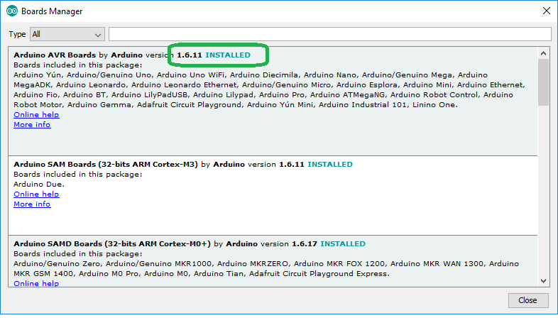
      1.8.4 of the IDE should be just fine, I'm using 1.8.5. But you need to check the AVR Boards definition you are using. 1.6.11 is know to work but newer versions are known to cause reboots in Ethernet GW and this is what seems to be happening for you.

      0_1524542298361_2a950b4e-442f-42dd-bfb5-5350b6e951cd-image.png

      posted in Vera
      korttoma
      korttoma
    • RE: No Inclusion

      I'm not sure I understand in what situation you get the above. Is it when you try to start inclusion from Vera?
      If it is then it seems like your GW is restarting and this is something that happens with some versions of the Arduino AVR Boards definition. Please check that you are using version 1.6.11 from the IDE Boards Manager (I think this is something that I have already mentioned to you in one of your other threads but lets check again).

      posted in Vera
      korttoma
      korttoma
    • RE: No Inclusion

      @mntlvr If you now try to start inclusion mode from your Vera you should see some event also in MYSController.

      posted in Vera
      korttoma
      korttoma
    • RE: No Inclusion

      @mntlvr In MYSController you just need to go to "Settings" and check "TCP/IP" and enter "IP" and "Port" and then "OK". And then you press the "Connect" button. Then you should see some messages under "Messages" and under "MYSController Debug" tabs.

      Now try restarting your node to see that it presents itself correctly.

      posted in Vera
      korttoma
      korttoma
    • RE: nRF5 action!

      @nca78 still not getting anywhere with this. Would you mind ziping your sketch folder, then I should have all the correct files (right?). If I still have issues to compile I must be missing some library or are using the wrong version of something.

      posted in My Project
      korttoma
      korttoma
    • RE: No Inclusion

      @mntlvr I think your best option to find your issue is to turn on debugging on your GW and check serial debug log. Allso if you happen to have a windows PC for your debuging you could try the MYSController to check if that one is working correctly. I kind of doubt that the issue is in Vera.

      posted in Vera
      korttoma
      korttoma
    • RE: nRF5 action!

      @nca78 I tried to follow your instructions in post #1514 but I must be doing something wrong when I add files from the NRF5 SDK to my sketch folder because I keep getting some errors about missing files, so I keep adding and now I got to this point:

      WARNING: Spurious .ci folder in 'MySensors' library
      WARNING: Spurious .mystools folder in 'MySensors' library
      In file included from C:\Users\Tomas\Documents\Arduino\NRF5SceneCtLC2Protoboard\NRF5SceneCtLC2Protoboard.ino:4:0:
      
      nrf_gpio.h:67: error: #error "Not supported."
      
       #error "Not supported."
      
        ^
      
      exit status 1
      #error "Not supported."
      
      posted in My Project
      korttoma
      korttoma
    • RE: πŸ’¬ Vera Controller

      @mntlvr There has been some issues with Ethernet type Gateways if the Arduino AVR Boards version is later than 1.6.11. I'm not sure if this affects the ESP8266 but it is worth giving it a try.
      Please try the Arduino AVR Boards version 1.6.11.

      posted in Announcements
      korttoma
      korttoma
    • RE: πŸ’¬ Vera Controller

      @mntlvr so you mean to connect 2 controllers to 1 gateway? I do not think you can run both serial and wifi/ethernet gateway on the same device at the same time. You can however connect more then one controller to an wifi/ethernet gateway if you define:

      
      #define MY_GATEWAY_MAX_CLIENTS	2	//Max number of parallel clients (sever mode).
      
      
      posted in Announcements
      korttoma
      korttoma
    • RE: vera

      @komal-save not quite sure what you mean but if your device is already included you should not need to do anything to reconnect even if the gateway is temporarily unavailable but restarting your node should make it reconnect immediately.

      If your node has not been included then you need to use the inclusion procedure, red more here ->
      Vera Controller

      posted in Vera
      korttoma
      korttoma
    • RE: Vera Plus and ESP8266

      @mntlvr I'm not sure what kind of serial chip is on the ESP8266 but Vera can not detect all types of serial chips because there are no drivers installed. FTDI chips should be detected by Vera automatically and then you just need to set the correct serial port settings:

      alt text

      posted in Troubleshooting
      korttoma
      korttoma
    • RE: nRF5 action!

      @nca78 πŸ‘ no hurry πŸ˜‰

      posted in My Project
      korttoma
      korttoma
    • RE: nRF5 action!

      @nca78 said in nRF5 Bluetooth action!:

      use the GPIOTE PORT event instead or the app_button libary.

      Thanks again for pointing out a possible solution but again I do not know how. I will just have to be patient and wait for someone to post an example of how to use one of the methods you mentioned.

      posted in My Project
      korttoma
      korttoma
    • RE: nRF5 action!

      @nca78 would you mind sharing your sketch files for your door sensors?
      As I'm not a programmer and not so good at programing I usually rely on example code to get anything done. More examples gives me more understanding how things should be done.

      posted in My Project
      korttoma
      korttoma
    • RE: nRF5 action!

      @nca78 it is ok, I think I will have to set up a test system with a different device with witch I can measure current consumption, attach serial logging and then try to fiddle with the code. I'm flying in the dark with this bluetooth beacon device since I cannot access any pins.

      posted in My Project
      korttoma
      korttoma
    • RE: nRF5 action!

      @nca78 sorry but I cannot figure out how to do this. Should I do it in the MyBoardNRF5.cpp, MyBoardNRF5.h or in the sketch?

      posted in My Project
      korttoma
      korttoma
    • RE: nRF5 action!

      I guess this is why I cant get LPCOMP to work on the device.

      Eight input options (AIN0 to AIN7)
      

      I would have to use the analog inputs because pin 28 is just a general purpose I/O pin.

      0_1521609771691_nrf51822-beacon-schematic.png

      0_1521609830464_nrf51822-beacon-schematic2.png

      posted in My Project
      korttoma
      korttoma
    • RE: nRF5 action!

      @nca78 thanks for the hint.

      I tried to merge my sketch with the code provided by @NeverDie but I can not seem to get it to detect my button and I don't quite understand where I should attach my button that is on pin 28 to the interrupt thingie.

      Here is my code now:

      //This sketch is applicable to Coincell Multisensor nRF51822, version 10
      
      // Define a static node address, remove if you want auto address assignment
      //#define MY_NODE_ID 26                                                          // KΓΆk
      #define MY_NODE_ID 27                                                          // Test device
                                                        
      
      // Enable and select radio type attached
      
      #define MY_RADIO_NRF5_ESB
      
      #define SN "NRF5 Scene"
      #define SV "1.0"
      
      #define CHILD_ID_SCENE 1
      
      //#define MY_CORE_ONLY
      
      
      #define IS_NRF51  //true iff the target is an nRF51.  If an nRF52, then comment this line out!
      
      // PIN for the buttons
      byte buttonOne = 28;
      
      //Bounce debouncer[NUMBUTTONS];
      int buttonOneoldValue;
      
      
      // Pin definitions
      //#define DIGITAL_INPUT_INT 28   // The digital input you attached your interrupt  (Only 2 and 3 generates interrupt!)
      
      
      //#define I2C_INTERRUPT_PIN PIN_BUTTON1
      //#define LEAK_DETECTION_PIN PIN_BUTTON1
      
      #include <nrf.h>
      #include <MySensors.h>
      
      volatile bool button_pressed=false;
      
      // Sensor messages
      MyMessage msgOn(CHILD_ID_SCENE, V_SCENE_ON);
      
      // Global settings
      uint16_t SceneOne = 0;
      uint16_t SceneTwo = 1;
      
      void blinkityBlink(uint8_t pulses, uint8_t repetitions) {
        for (int x=0;x<repetitions;x++) {
          for (int i=0;i<pulses;i++) {
            digitalWrite(LED_BUILTIN,HIGH);
            wait(20);
            digitalWrite(LED_BUILTIN,LOW);
            wait(100);
          }    
            wait(500);
        }
      }
      
      void disableNfc() {  //only applied to nRF52
      
      #ifndef IS_NRF51
        //Make pins 9 and 10 usable as GPIO pins.
        NRF_NFCT->TASKS_DISABLE=1;  //disable NFC
        NRF_NVMC->CONFIG=1;  // Write enable the UICR
        NRF_UICR->NFCPINS=0; //Make pins 9 and 10 usable as GPIO pins.
        NRF_NVMC->CONFIG=0;  // Put the UICR back into read-only mode.
      #endif
      }
      
      
      void turnOffRadio() {
        NRF_RADIO->TASKS_DISABLE=1;
        while (!(NRF_RADIO->EVENTS_DISABLED)) {}  //until radio is confirmed disabled
      }
      
      void turnOffUarte0() {
      #ifndef IS_NRF51  
        NRF_UARTE0->TASKS_STOPRX = 1;
        NRF_UARTE0->TASKS_STOPTX = 1;
        NRF_UARTE0->TASKS_SUSPEND = 1;
        NRF_UARTE0->ENABLE=0;  //disable UART0
        while (NRF_UARTE0->ENABLE!=0) {};  //wait until UART0 is confirmed disabled.
      #endif
      
      #ifdef IS_NRF51
        NRF_UART0->TASKS_STOPRX = 1;
        NRF_UART0->TASKS_STOPTX = 1;
        NRF_UART0->TASKS_SUSPEND = 1;
        NRF_UART0->ENABLE=0;  //disable UART0
        while (NRF_UART0->ENABLE!=0) {};  //wait until UART0 is confirmed disabled.
      #endif
      }
      
      void turnOffAdc() {
      #ifndef IS_NRF51
        if (NRF_SAADC->ENABLE) { //if enabled, then disable the SAADC
          NRF_SAADC->TASKS_STOP=1;
          while (NRF_SAADC->EVENTS_STOPPED) {} //wait until stopping of SAADC is confirmed
          NRF_SAADC->ENABLE=0;  //disable the SAADC
          while (NRF_SAADC->ENABLE) {} //wait until the disable is confirmed
        }
      #endif
      }
      
      
      void turnOffHighFrequencyClock() {
          NRF_CLOCK->TASKS_HFCLKSTOP = 1;
          while ((NRF_CLOCK->HFCLKSTAT) & 0x0100) {}  //wait as long as HF clock is still running.
      }
      
      
      void mySleepPrepare()
      {
        turnOffHighFrequencyClock();
        turnOffRadio();
        turnOffUarte0();
      }
       
      
      void activateLpComp() {
        //NRF_LPCOMP->PSEL=1; // monitor AIN1 (pin P0.03 on nRF52832 test board).
        //while (!(NRF_LPCOMP->PSEL==1)) {} //wait until confirmed
        NRF_LPCOMP->PSEL=3; // monitor AIN3 (pin P0.02 on nRF51822 for coincell_multisensor_v10)
        while (!(NRF_LPCOMP->PSEL==3)) {} //wait until confirmed
        NRF_LPCOMP->REFSEL=1;  // choose 1/4 VDD as the reference voltage
        while (!(NRF_LPCOMP->REFSEL==1)) {} //wait until confirmed
        NRF_LPCOMP->ANADETECT=1;  //detect UP events.
        while (NRF_LPCOMP->ANADETECT!=1) {} //wait until confirmed
        NRF_LPCOMP->INTENSET=B0100;  //Enable interrupt for UP event
        while (!(NRF_LPCOMP->INTENSET==B0100)) {} //wait until confirmed
        NRF_LPCOMP->ENABLE=1;  //Enable LPCOMP
        while (!(NRF_LPCOMP->ENABLE==1)) {} //wait until confirmed
        NRF_LPCOMP->TASKS_START=1;  //start the LPCOMP
        while (!(NRF_LPCOMP->EVENTS_READY)) {}  //wait until ready
        
        NVIC_SetPriority(LPCOMP_IRQn, 15);
        NVIC_ClearPendingIRQ(LPCOMP_IRQn);
        NVIC_EnableIRQ(LPCOMP_IRQn);
      }
      
      void suspendLpComp() { //suspend getting more interrupts from LPCOMP before the first interrupt can be handled
        if ((NRF_LPCOMP->ENABLE) && (NRF_LPCOMP->EVENTS_READY)) {  //if LPCOMP is enabled
          NRF_LPCOMP->INTENCLR=B0100;  //disable interrupt from LPCOMP
          while (NRF_LPCOMP->INTENCLR==B0100) {} //wait until confirmed
        }
      }
      
      void resumeLpComp() { //suspend getting interrupts from LPCOMP
        NRF_LPCOMP->INTENSET=B0100;  //Enable interrupt for UP event
        while (!(NRF_LPCOMP->INTENSET==B0100)) {} //wait until confirmed
      }
      
      /****************************************************
       *
       * Setup code 
       *
       ****************************************************/
       
      void setup() {
      
        hwInit();
        hwPinMode(LED_BUILTIN,OUTPUT_D0H1);
        disableNfc();
        turnOffAdc();
        activateLpComp();
        blinkityBlink(2,1);  //Signify end of setup with two quick pulses.
        mySleepPrepare();
        button_pressed=false;
      
        //NRF_CLOCK->INTENSET=B11;  //enable interrupts for EVENTS_HFCLKSTARTED and  EVENTS_LFCLKSTARTED
       // NRF_CLOCK->TASKS_HFCLKSTART=1;  //start the high frequency crystal oscillator clock
       // while (!(NRF_CLOCK->EVENTS_HFCLKSTARTED)) {} //wait until high frequency crystal oscillator clock is up to speed and working
                                                      
        //hwPinMode(DIGITAL_INPUT_INT, INPUT_PULLUP);
          
          /// Make input & enable pull-up resistors on switch pins
        hwPinMode(buttonOne, INPUT_PULLUP);
        //buttonOneoldValue = -1;
        
      
        //sendBattLevel();
        
      
      }
      
      void presentation()  {
        sendSketchInfo(SN, SV);
        //present the scene controller to gateway
        wait(10);
        present(CHILD_ID_SCENE, S_SCENE_CONTROLLER);
            
        wait(10);
        sendBattLevel();
        
      }
      
      void sendBattLevel()
      {
          long vcc = hwCPUVoltage();
        
          // Calculate percentage
      
          vcc = vcc - 1800; // subtract 1.9V from vcc, as this is the lowest voltage we will operate at
          
          long percent = vcc / 14.0;
          sendBatteryLevel(percent);    
        
      }
      
      void loop() {
      
        sleep(10000);  //sleep for 5 seconds.
        mySleepPrepare();  //An ounce of prevention: Turn-off HF clock, etc, ASAP to save power, just in case the library's sleep() routine resumed them.
        if (button_pressed) {   //if a leak is detected
          suspendLpComp(); //suspend LPCOMP to prevent multiple interrupts
          //blinkityBlink(10,3);  //blink a lot to show that a leak was detected.
          send(msgOn.set(SceneOne));
              
              wait(20);
      
              send(msgOn.set(SceneTwo));
      
              sendBattLevel();
          button_pressed=false;  //Clear the semaphore
          NRF_LPCOMP->EVENTS_UP=0;  //Clear the semaphore
          resumeLpComp();  //operations of LPCOMP were suspended after detecting the LPCOMP iterrupt
        }
        else {
          blinkityBlink(1,1);  //otherwise, just one short blink to indicate the wakeup was scheduled by the RTC
        }
      }
      
      
      // * Reset events and read back on nRF52
      //* http://infocenter.nordicsemi.com/pdf/nRF52_Series_Migration_v1.0.pdf
       
      #if __CORTEX_M == 0x04
      #define NRF5_RESET_EVENT(event)                                                 \
              event = 0;                                                                   \
              (void)event
      #else
      #define NRF5_RESET_EVENT(event) event = 0
      #endif
      
      
      // This must be in one line
      extern "C" { void LPCOMP_IRQHandler(void) {button_pressed=true; NRF5_RESET_EVENT(NRF_LPCOMP->EVENTS_UP); NRF_LPCOMP->EVENTS_UP=0; MY_HW_RTC->CC[0]=(MY_HW_RTC->COUNTER+2);}}
      

      I thought that I should do it like this:

      void activateLpComp() {
         NRF_LPCOMP->PSEL=28; // monitor AIN3 (pin P0.02 on nRF51822 for coincell_multisensor_v10)
        while (!(NRF_LPCOMP->PSEL==28)) {} //wait until confirmed
      

      But then it does not seem to run the loop anymore because I do not get the 10s blink.

      posted in My Project
      korttoma
      korttoma
    • RE: nRF5 action!

      @Mika what is your experience regarding battery consumption on these?

      LINK

      I put together a sketch witch seems to work fine but one CR2032 just lasts a couple of days.

      Sketch:

      /**
       * The MySensors Arduino library handles the wireless radio link and protocol
       * between your home built sensors/actuators and HA controller of choice.
       * The sensors forms a self healing radio network with optional repeaters. Each
       * repeater and gateway builds a routing tables in EEPROM which keeps track of the
       * network topology allowing messages to be routed to nodes.
       *
       * Created by Henrik Ekblad <henrik.ekblad@mysensors.org>
       * Copyright (C) 2013-2015 Sensnology AB
       * Full contributor list: https://github.com/mysensors/Arduino/graphs/contributors
       *
       * Documentation: http://www.mysensors.org
       * Support Forum: http://forum.mysensors.org
       *
       * This program is free software; you can redistribute it and/or
       * modify it under the terms of the GNU General Public License
       * version 2 as published by the Free Software Foundation.
       *
       *******************************
       */
      
      // Enable debug prints to serial monitor
      //#define MY_DEBUG 
      
      // Define a static node address, remove if you want auto address assignment
      //#define MY_NODE_ID 26                                                          // KΓΆk
      #define MY_NODE_ID 27                                                          // Test device
                                                        
      
      // Enable and select radio type attached
      
      #define MY_RADIO_NRF5_ESB
      
      #include <MySensors.h>
      
      #define SN "NRF5 Scene"
      #define SV "1.0"
      
      #define CHILD_ID_SCENE 1
      
      // PIN for the buttons
      byte buttonOne = 28;
      
      //Bounce debouncer[NUMBUTTONS];
      int buttonOneoldValue;
      
      
      // Pin definitions
      #define DIGITAL_INPUT_INT 28   // The digital input you attached your interrupt  (Only 2 and 3 generates interrupt!)
      
      
      // Sensor messages
      MyMessage msgOn(CHILD_ID_SCENE, V_SCENE_ON);
      
      // Global settings
      uint16_t SceneOne = 0;
      uint16_t SceneTwo = 1;
      
      
      void blinkityBlink(uint8_t repetitions) {
        for (int x=0;x<repetitions;x++) {
          digitalWrite(LED_BUILTIN,HIGH);
          wait(20);
          digitalWrite(LED_BUILTIN,LOW);
          wait(100);
          digitalWrite(LED_BUILTIN,HIGH);
          wait(20);
          digitalWrite(LED_BUILTIN,LOW);    
          if (x<(repetitions-1)) {  //skip waiting at the end of the final repetition
            wait(500);
          }
        }
      }
      
      
      /****************************************************
       *
       * Setup code 
       *
       ****************************************************/
       
      void setup() {
        
        hwPinMode(LED_BUILTIN,OUTPUT_D0H1);
        blinkityBlink(2);  //signify power-up and start of operations
      
        NRF_CLOCK->INTENSET=B11;  //enable interrupts for EVENTS_HFCLKSTARTED and  EVENTS_LFCLKSTARTED
        NRF_CLOCK->TASKS_HFCLKSTART=1;  //start the high frequency crystal oscillator clock
        while (!(NRF_CLOCK->EVENTS_HFCLKSTARTED)) {} //wait until high frequency crystal oscillator clock is up to speed and working
                                                      
        hwPinMode(DIGITAL_INPUT_INT, INPUT_PULLUP);
          
          /// Make input & enable pull-up resistors on switch pins
        hwPinMode(buttonOne, INPUT_PULLUP);
        buttonOneoldValue = -1;
        
      
        sendBattLevel();
        
      
      }
      
      void presentation()  {
        sendSketchInfo(SN, SV);
        //present the scene controller to gateway
        wait(10);
        present(CHILD_ID_SCENE, S_SCENE_CONTROLLER);
            
        wait(10);
      }
      
      
      /***********************************************
       *
       *  Main loop function
       *
       ***********************************************/
      void loop() {
        
        // Check for button activity
           
        int value = digitalRead(buttonOne);
          
        if (value != buttonOneoldValue)
          {
            // Send in the new value
            if (value == LOW)                                                      
            {
              send(msgOn.set(SceneOne));
              
              wait(20);
      
              send(msgOn.set(SceneTwo));
      
              sendBattLevel();
                    
      
            }
            buttonOneoldValue = value;
          }
          
        sleep(digitalPinToInterrupt(DIGITAL_INPUT_INT), CHANGE, 0);  
        
      }


      /********************************************
       *
       * Sends battery information (battery percentage)
       *
       * Parameters
       * - force : Forces transmission of a value
       *
       *******************************************/
      void sendBattLevel()
      {
          long vcc = hwCPUVoltage();
        
          // Calculate percentage
      
          vcc = vcc - 1800; // subtract 1.9V from vcc, as this is the lowest voltage we will operate at
          
          long percent = vcc / 14.0;
          sendBatteryLevel(percent);    
        
      }
      

      I noticed that the chip sais:
      N51822
      QFABC0
      1646UU

      QFAB translates to 16kB RAM, 128kB flash and I can not even select this option in the arduino IDE. Can this be the problem?

      @d00616 refer to his document for some high current consumption issue but I'm not sure what to do with the info.

      Is there something wrong with my sketch or is there just an old crappy chip on the device??

      posted in My Project
      korttoma
      korttoma
    • RE: some sort of a binary sensor for Vera?

      Hi @JohnRob, I usually present binary sensors as Motion sensors in Vera.

      posted in Vera
      korttoma
      korttoma
    • RE: πŸ’¬ Vera Controller

      @scottdube I'm not quite sure what you are saying here but using the port 5003 on an MySensors Ethernet GW should not be a problem.

      I have the latest firmware on both my VeraLite and my VeraPlus and use 3 MySensors Ethernet GW on port 5003.

      0_1521183177284_22d607c0-0b7e-4587-9dc9-e0dc5a3d1cb9-image.png

      Did you enable the inclusion mode?

      // Enable inclusion mode
      #define MY_INCLUSION_MODE_FEATURE
      
      posted in Announcements
      korttoma
      korttoma
    • RE: nRF5 action!

      @nca78 πŸ˜„ that worked! thank you thank you thank you!

      My first NFR5 node is ALIVE!

      posted in My Project
      korttoma
      korttoma
    • RE: nRF5 action!

      Like NeverDie I am also having some trouble getting started with the NRF5 programming.

      Here is my setup:
      0_1520490115123_34a8da45-4d3b-4909-aaf7-3ded3b98590e-image.png

      0_1520490137522_9ec65e79-3f29-4b9d-b503-925df3f590bb-image.png

      The problem "No valid JTAG Interface Configured":
      0_1520490174588_f762683c-2c6d-42ce-ae83-f3baf5f38a7e-image.png

      Did I miss some step to configure the J-Link somewhere?

      posted in My Project
      korttoma
      korttoma
    • RE: Efergy e2 power meter

      @ailiev it "works" without the receiver but for me the node fails after about 1h so I gave up. I could try again now with the new MySensors 2.2.0 lib to see if it makes any difference (when I find some time).

      posted in My Project
      korttoma
      korttoma
    • RE: [SOLVED] MY_RFM69_NEW_DRIVER, SensebenderGW, SensebenderMicro

      @tekka updated the GW with the Dev branch Lib (2.2.1-alpha) and now it seems to be working! πŸ˜„

      update: Also updated the SensebenderMicro Node with the Dev branch Lib (2.2.1-alpha) and it is stil working πŸ‘ thanks @tekka

      posted in Troubleshooting
      korttoma
      korttoma
    • RE: [SOLVED] MY_RFM69_NEW_DRIVER, SensebenderGW, SensebenderMicro

      Maybe @Anticimex has some thought about this? Did you try the RFM69/W5100 combination on the SensebenderGW with or without the "#define MY_RFM69_NEW_DRIVER"?

      posted in Troubleshooting
      korttoma
      korttoma
    • RE: [SOLVED] MY_RFM69_NEW_DRIVER, SensebenderGW, SensebenderMicro

      @gohan said in MY_RFM69_NEW_DRIVER, SensebenderGW, SensebenderMicro:

      W5100 and RFM69

      I do not believe that this is a W5100 and RFM69 issue since the old RFM69 driver works just fine.
      And yes I have also tried commenting the line you suggested. I believe that the issue is with running the new RFM69 driver on SAMD Board somehow.

      posted in Troubleshooting
      korttoma
      korttoma
    • RE: [SOLVED] MY_RFM69_NEW_DRIVER, SensebenderGW, SensebenderMicro

      Tested with serial GW sketch on the SensebenderGW instead:

      GW log:

      0;255;3;0;9;670 RFM69:INIT
      0;255;3;0;9;685 RFM69:INIT:PIN,CS=30,IQP=32,IQN=32,RST=43
      0;255;3;0;9;695 RFM69:PTX:LEVEL=5 dBm
      0;255;3;0;14;Gateway startup complete.
      0;255;0;0;18;2.2.0
      0;255;3;0;9;19524 RFM69:SWR:SEND,TO=17,RETRY=0
      0;255;3;0;9;19737 !RFM69:SWR:NACK
      0;255;3;0;9;19747 RFM69:SWR:SEND,TO=17,RETRY=1
      0;255;3;0;9;19767 RFM69:SWR:ACK,FROM=17,SEQ=1,RSSI=-61
      0;255;3;0;9;26296 RFM69:SWR:SEND,TO=17,RETRY=0
      0;255;3;0;9;26316 RFM69:SWR:ACK,FROM=17,SEQ=2,RSSI=-54
      0;255;3;0;9;27455 RFM69:SAC:SEND ACK,TO=17,RSSI=-60
      0;255;3;0;9;27472 RFM69:SWR:SEND,TO=17,RETRY=0
      0;255;3;0;9;27492 RFM69:SWR:ACK,FROM=17,SEQ=4,RSSI=-54
      0;255;3;0;9;27514 RFM69:SAC:SEND ACK,TO=17,RSSI=-60
      0;255;3;0;9;27526 RFM69:SWR:SEND,TO=17,RETRY=0
      0;255;3;0;9;27546 RFM69:SWR:ACK,FROM=17,SEQ=6,RSSI=-54
      0;255;3;0;9;27560 RFM69:SAC:SEND ACK,TO=17,RSSI=-60
      17;255;0;0;17;2.2.0
      0;255;3;0;9;27592 RFM69:SAC:SEND ACK,TO=17,RSSI=-60
      17;255;3;0;6;0
      0;255;3;0;9;29620 RFM69:SAC:SEND ACK,TO=17,RSSI=-61
      17;255;3;0;11;Sensebender Micro
      0;255;3;0;9;29654 RFM69:SAC:SEND ACK,TO=17,RSSI=-61
      17;255;3;0;12;1.4
      0;255;3;0;9;29686 RFM69:SAC:SEND ACK,TO=17,RSSI=-61
      17;1;0;0;6;
      0;255;3;0;9;29717 RFM69:SAC:SEND ACK,TO=17,RSSI=-60
      17;2;0;0;7;
      0;255;3;0;9;29750 RFM69:SAC:SEND ACK,TO=17,RSSI=-61
      0;255;3;0;9;29767 RFM69:SWR:SEND,TO=17,RETRY=0
      0;255;3;0;9;29787 RFM69:SWR:ACK,FROM=17,SEQ=14,RSSI=-54
      0;255;3;0;9;29831 RFM69:SAC:SEND ACK,TO=17,RSSI=-61
      17;1;1;0;0;28.1
      0;255;3;0;9;29863 RFM69:SAC:SEND ACK,TO=17,RSSI=-61
      17;2;1;0;1;25
      0;255;3;0;9;29897 RFM69:SAC:SEND ACK,TO=17,RSSI=-61
      17;255;3;0;0;101
      0;255;3;0;9;48872 RFM69:SWR:SEND,TO=17,RETRY=0
      0;255;3;0;9;48892 RFM69:SWR:ACK,FROM=17,SEQ=18,RSSI=-54
      0;255;3;0;9;50007 RFM69:SAC:SEND ACK,TO=17,RSSI=-61
      0;255;3;0;9;50024 RFM69:SWR:SEND,TO=17,RETRY=0
      0;255;3;0;9;50044 RFM69:SWR:ACK,FROM=17,SEQ=20,RSSI=-54
      0;255;3;0;9;50066 RFM69:SAC:SEND ACK,TO=17,RSSI=-61
      0;255;3;0;9;50078 RFM69:SWR:SEND,TO=17,RETRY=0
      0;255;3;0;9;50098 RFM69:SWR:ACK,FROM=17,SEQ=22,RSSI=-54
      0;255;3;0;9;50112 RFM69:SAC:SEND ACK,TO=17,RSSI=-61
      17;255;0;0;17;2.2.0
      0;255;3;0;9;50144 RFM69:SAC:SEND ACK,TO=17,RSSI=-61
      17;255;3;0;6;0
      0;255;3;0;9;52172 RFM69:SAC:SEND ACK,TO=17,RSSI=-61
      17;255;3;0;11;Sensebender Micro
      0;255;3;0;9;52206 RFM69:SAC:SEND ACK,TO=17,RSSI=-61
      17;255;3;0;12;1.4
      0;255;3;0;9;52238 RFM69:SAC:SEND ACK,TO=17,RSSI=-61
      17;1;0;0;6;
      0;255;3;0;9;52269 RFM69:SAC:SEND ACK,TO=17,RSSI=-61
      17;2;0;0;7;
      0;255;3;0;9;52302 RFM69:SAC:SEND ACK,TO=17,RSSI=-61
      0;255;3;0;9;52319 RFM69:SWR:SEND,TO=17,RETRY=0
      0;255;3;0;9;52532 !RFM69:SWR:NACK
      0;255;3;0;9;52574 RFM69:SWR:SEND,TO=17,RETRY=1
      0;255;3;0;9;52787 !RFM69:SWR:NACK
      0;255;3;0;9;52829 RFM69:SWR:SEND,TO=17,RETRY=2
      0;255;3;0;9;52849 RFM69:SWR:ACK,FROM=17,SEQ=30,RSSI=-54
      0;255;3;0;9;52893 RFM69:SAC:SEND ACK,TO=17,RSSI=-61
      17;1;1;0;0;28.1
      0;255;3;0;9;52925 RFM69:SAC:SEND ACK,TO=17,RSSI=-61
      17;2;1;0;1;23
      0;255;3;0;9;52959 RFM69:SAC:SEND ACK,TO=17,RSSI=-61
      17;255;3;0;0;101
      0;255;3;0;9;116786 RFM69:SAC:SEND ACK,TO=17,RSSI=-54
      17;1;1;0;0;27.6
      0;255;3;0;9;116818 RFM69:SAC:SEND ACK,TO=17,RSSI=-54
      17;2;1;0;1;16
      0;255;3;0;9;180582 RFM69:SAC:SEND ACK,TO=17,RSSI=-56
      17;1;1;0;0;27.5
      0;255;3;0;9;180614 RFM69:SAC:SEND ACK,TO=17,RSSI=-56
      17;2;1;0;1;10
      

      Node log:

      __  __       ____
      |  \/  |_   _/ ___|  ___ _ __  ___  ___  _ __ ___
      | |\/| | | | \___ \ / _ \ `_ \/ __|/ _ \| `__/ __|
      | |  | | |_| |___| |  __/ | | \__ \  _  | |  \__ \
      |_|  |_|\__, |____/ \___|_| |_|___/\___/|_|  |___/
              |___/                      2.2.0
      
      16 MCO:BGN:INIT NODE,CP=RPNNA---,VER=2.2.0
      26 TSM:INIT
      28 TSF:WUR:MS=0
      30 RFM69:INIT
      30 RFM69:INIT:PIN,CS=10,IQP=2,IQN=0
      36 RFM69:PTX:LEVEL=5 dBm
      38 TSM:INIT:TSP OK
      40 TSM:INIT:STATID=17
      43 TSF:SID:OK,ID=17
      45 TSM:FPAR
      47 RFM69:SWR:SEND,TO=255,RETRY=0
      53 TSF:MSG:SEND,17-17-255-255,s=255,c=3,t=7,pt=0,l=0,sg=0,ft=0,st=OK:
      950 RFM69:SAC:SEND ACK,TO=0,RSSI=-54
      956 TSF:MSG:READ,0-0-17,s=255,c=3,t=8,pt=1,l=1,sg=0:0
      962 TSF:MSG:FPAR OK,ID=0,D=1
      2062 TSM:FPAR:OK
      2062 TSM:ID
      2064 TSM:ID:OK
      2066 TSM:UPL
      2068 RFM69:SWR:SEND,TO=0,RETRY=0
      2086 RFM69:SWR:ACK,FROM=0,SEQ=3,RSSI=-61
      2091 TSF:MSG:SEND,17-17-0-0,s=255,c=3,t=24,pt=1,l=1,sg=0,ft=0,st=OK:1
      2105 RFM69:SAC:SEND ACK,TO=0,RSSI=-54
      2111 TSF:MSG:READ,0-0-17,s=255,c=3,t=25,pt=1,l=1,sg=0:1
      2117 TSF:MSG:PONG RECV,HP=1
      2121 TSM:UPL:OK
      2121 TSM:READY:ID=17,PAR=0,DIS=1
      2125 RFM69:SWR:SEND,TO=0,RETRY=0
      2146 RFM69:SWR:ACK,FROM=0,SEQ=5,RSSI=-61
      2150 TSF:MSG:SEND,17-17-0-0,s=255,c=3,t=15,pt=6,l=2,sg=0,ft=0,st=OK:0100
      2158 RFM69:SAC:SEND ACK,TO=0,RSSI=-54
      2166 TSF:MSG:READ,0-0-17,s=255,c=3,t=15,pt=6,l=2,sg=0:0100
      2172 RFM69:SWR:SEND,TO=0,RETRY=0
      2193 RFM69:SWR:ACK,FROM=0,SEQ=7,RSSI=-61
      2197 TSF:MSG:SEND,17-17-0-0,s=255,c=0,t=17,pt=0,l=5,sg=0,ft=0,st=OK:2.2.0
      2205 RFM69:SWR:SEND,TO=0,RETRY=0
      2224 RFM69:SWR:ACK,FROM=0,SEQ=8,RSSI=-61
      2228 TSF:MSG:SEND,17-17-0-0,s=255,c=3,t=6,pt=1,l=1,sg=0,ft=0,st=OK:0
      4237 RFM69:SWR:SEND,TO=0,RETRY=0
      4259 RFM69:SWR:ACK,FROM=0,SEQ=9,RSSI=-61
      4263 TSF:MSG:SEND,17-17-0-0,s=255,c=3,t=11,pt=0,l=17,sg=0,ft=0,st=OK:Sensebender Micro
      4272 RFM69:SWR:SEND,TO=0,RETRY=0
      4292 RFM69:SWR:ACK,FROM=0,SEQ=10,RSSI=-61
      4296 TSF:MSG:SEND,17-17-0-0,s=255,c=3,t=12,pt=0,l=3,sg=0,ft=0,st=OK:1.4
      4304 RFM69:SWR:SEND,TO=0,RETRY=0
      4325 RFM69:SWR:ACK,FROM=0,SEQ=11,RSSI=-61
      4329 TSF:MSG:SEND,17-17-0-0,s=1,c=0,t=6,pt=0,l=0,sg=0,ft=0,st=OK:
      4337 RFM69:SWR:SEND,TO=0,RETRY=0
      4356 RFM69:SWR:ACK,FROM=0,SEQ=12,RSSI=-61
      4360 TSF:MSG:SEND,17-17-0-0,s=2,c=0,t=7,pt=0,l=0,sg=0,ft=0,st=OK:
      4368 MCO:REG:REQ
      4370 RFM69:SWR:SEND,TO=0,RETRY=0
      4388 RFM69:SWR:ACK,FROM=0,SEQ=13,RSSI=-61
      4395 TSF:MSG:SEND,17-17-0-0,s=255,c=3,t=26,pt=1,l=1,sg=0,ft=0,st=OK:2
      4919 RFM69:SAC:SEND ACK,TO=0,RSSI=-54
      4925 TSF:MSG:READ,0-0-17,s=255,c=3,t=27,pt=1,l=1,sg=0:1
      4931 MCO:PIM:NODE REG=1
      4933 MCO:BGN:STP
      Sensebender Micro FW 1.4 - Online!
      isMetric: 1
      TempDiff :128.10
      HumDiff  :123.00
      T: 28.10
      H: 23
      4962 RFM69:SWR:SEND,TO=0,RETRY=0
      4982 RFM69:SWR:ACK,FROM=0,SEQ=15,RSSI=-61
      4986 TSF:MSG:SEND,17-17-0-0,s=1,c=1,t=0,pt=7,l=5,sg=0,ft=0,st=OK:28.1
      4995 RFM69:SWR:SEND,TO=0,RETRY=0
      5015 RFM69:SWR:ACK,FROM=0,SEQ=16,RSSI=-61
      5019 TSF:MSG:SEND,17-17-0-0,s=2,c=1,t=1,pt=2,l=2,sg=0,ft=0,st=OK:23
      5029 RFM69:SWR:SEND,TO=0,RETRY=0
      5048 RFM69:SWR:ACK,FROM=0,SEQ=17,RSSI=-61
      5052 TSF:MSG:SEND,17-17-0-0,s=255,c=3,t=0,pt=1,l=1,sg=0,ft=0,st=OK:101
      5060 MCO:BGN:INIT OK,TSP=1
      TempDiff :0.05
      HumDiff  :0.00
      5083 MCO:SLP:MS=60000,SMS=0,I1=255,M1=255,I2=255,M2=255
      5091 TSF:TDI:TSL
      5091 RFM69:RSL
      5095 MCO:SLP:WUP=-1
      5097 TSF:TRI:TSB
      5099 RFM69:RSB
      TempDiff :0.51
      HumDiff  :3.50
      T: 27.59
      H: 16
      5122 RFM69:SWR:SEND,TO=0,RETRY=0
      5142 RFM69:SWR:ACK,FROM=0,SEQ=18,RSSI=-54
      5146 TSF:MSG:SEND,17-17-0-0,s=1,c=1,t=0,pt=7,l=5,sg=0,ft=0,st=OK:27.6
      5154 RFM69:SWR:SEND,TO=0,RETRY=0
      5175 RFM69:SWR:ACK,FROM=0,SEQ=19,RSSI=-54
      5179 TSF:MSG:SEND,17-17-0-0,s=2,c=1,t=1,pt=2,l=2,sg=0,ft=0,st=OK:16
      5187 MCO:SLP:MS=60000,SMS=0,I1=255,M1=255,I2=255,M2=255
      5193 TSF:TDI:TSL
      5193 RFM69:RSL
      5197 MCO:SLP:WUP=-1
      5199 TSF:TRI:TSB
      5201 RFM69:RSB
      TempDiff :0.08
      HumDiff  :3.00
      T: 27.51
      H: 10
      5224 RFM69:SWR:SEND,TO=0,RETRY=0
      5244 RFM69:SWR:ACK,FROM=0,SEQ=20,RSSI=-56
      5249 TSF:MSG:SEND,17-17-0-0,s=1,c=1,t=0,pt=7,l=5,sg=0,ft=0,st=OK:27.5
      5257 RFM69:SWR:SEND,TO=0,RETRY=0
      5277 RFM69:SWR:ACK,FROM=0,SEQ=21,RSSI=-56
      5281 TSF:MSG:SEND,17-17-0-0,s=2,c=1,t=1,pt=2,l=2,sg=0,ft=0,st=OK:10
      5289 MCO:SLP:MS=60000,SMS=0,I1=255,M1=255,I2=255,M2=255
      5296 TSF:TDI:TSL
      5296 RFM69:RSL
      5300 MCO:SLP:WUP=-1
      5302 TSF:TRI:TSB
      5304 RFM69:RSB
      TempDiff :0.11
      HumDiff  :0.00
      5324 MCO:SLP:MS=60000,SMS=0,I1=255,M1=255,I2=255,M2=255
      5330 TSF:TDI:TSL
      5332 RFM69:RSL
      

      Seems to work just fine so I guess there is something wrong with using the W5100/NEW_RFM69 GW code on the sensebender?
      Or did I make a mistake in the GW sketch that only affects the NEW RFM69 driver?

      posted in Troubleshooting
      korttoma
      korttoma
    • [SOLVED] MY_RFM69_NEW_DRIVER, SensebenderGW, SensebenderMicro

      I can't seem to get the NEW RFM69 driver to work. I have a SensebenderGW and a SensebenderMicro. It seems to work just fine with the old driver, so if I comment out the following line it works nicely:

      #define MY_RFM69_NEW_DRIVER

      GW sketch:

       * The MySensors Arduino library handles the wireless radio link and protocol
       * between your home built sensors/actuators and HA controller of choice.
       * The sensors forms a self healing radio network with optional repeaters. Each
       * repeater and gateway builds a routing tables in EEPROM which keeps track of the
       * network topology allowing messages to be routed to nodes.
       *
       * Created by Henrik Ekblad <henrik.ekblad@mysensors.org>
       * Copyright (C) 2013-2015 Sensnology AB
       * Full contributor list: https://github.com/mysensors/Arduino/graphs/contributors
       *
       * Documentation: http://www.mysensors.org
       * Support Forum: http://forum.mysensors.org
       *
       * This program is free software; you can redistribute it and/or
       * modify it under the terms of the GNU General Public License
       * version 2 as published by the Free Software Foundation.
       *
       *******************************
       *
       * REVISION HISTORY
       * Version 1.0 - Henrik EKblad
       * Contribution by a-lurker and Anticimex,
       * Contribution by Norbert Truchsess <norbert.truchsess@t-online.de>
       * Contribution by Tomas Hozza <thozza@gmail.com>
       *
       *
       * DESCRIPTION
       * The EthernetGateway sends data received from sensors to the ethernet link.
       * The gateway also accepts input on ethernet interface, which is then sent out to the radio network.
       *
       * The GW code is designed for Arduino 328p / 16MHz.  ATmega168 does not have enough memory to run this program.
       *
       * LED purposes:
       * - To use the feature, uncomment MY_DEFAULT_xxx_LED_PIN in the sketch below
       * - RX (green) - blink fast on radio message recieved. In inclusion mode will blink fast only on presentation recieved
       * - TX (yellow) - blink fast on radio message transmitted. In inclusion mode will blink slowly
       * - ERR (red) - fast blink on error during transmission error or recieve crc error
       *
       * See http://www.mysensors.org/build/ethernet_gateway for wiring instructions.
       *
       */
      
       // Enable debug prints to serial monitor
      #define MY_DEBUG 
      
      #define SN "EthGW/RFM69 Rele Button"
      #define SV "1.5"
      
      // Enable and select radio type attached
      //#define MY_RADIO_NRF24
      //#define MY_RADIO_NRF5_ESB
      #define MY_RADIO_RFM69
      #define MY_RFM69_FREQUENCY RFM69_433MHZ
      #define MY_RFM69_NEW_DRIVER
      #define MY_RFM69_ATC_MODE_DISABLED
      #define MY_IS_RFM69HW
      //#define MY_RFM69_NETWORKID 105
      //#define MY_RF69_SPI_CS 29
      
      #define MY_DEBUG_VERBOSE_RFM69
      
      #define MY_BAUD_RATE 38400
      
      
      // Enable gateway ethernet module type
      #define MY_GATEWAY_W5100
      #define MY_GATEWAY_MAX_CLIENTS 2
      
      // W5100 Ethernet module SPI enable (optional if using a shield/module that manages SPI_EN signal)
      //#define MY_W5100_SPI_EN 4
      
      // Enable Soft SPI for NRF radio (note different radio wiring is required)
      // The W5100 ethernet module seems to have a hard time co-operate with
      // radio on the same spi bus.
      #if !defined(MY_W5100_SPI_EN) && !defined(ARDUINO_ARCH_SAMD)
      #define MY_SOFTSPI
      #define MY_SOFT_SPI_SCK_PIN 14
      #define MY_SOFT_SPI_MISO_PIN 16
      #define MY_SOFT_SPI_MOSI_PIN 15
      #endif
      
      // When W5100 is connected we have to move CE/CSN pins for NRF radio
      #ifndef MY_RF24_CE_PIN
      #define MY_RF24_CE_PIN 5
      #endif
      #ifndef MY_RF24_CS_PIN
      #define MY_RF24_CS_PIN 6
      #endif
      
      // Enable UDP communication
      //#define MY_USE_UDP  // If using UDP you need to set MY_CONTROLLER_IP_ADDRESS below
      
      // Enable MY_IP_ADDRESS here if you want a static ip address (no DHCP)
      #define MY_IP_ADDRESS 192,168,1,100
      
      // If using static ip you can define Gateway and Subnet address as well
      //#define MY_IP_GATEWAY_ADDRESS 192,168,178,1
      //#define MY_IP_SUBNET_ADDRESS 255,255,255,0
      
      // Renewal period if using DHCP
      //#define MY_IP_RENEWAL_INTERVAL 60000
      
      // The port to keep open on node server mode / or port to contact in client mode
      #define MY_PORT 5003
      
      // Controller ip address. Enables client mode (default is "server" mode).
      // Also enable this if MY_USE_UDP is used and you want sensor data sent somewhere.
      //#define MY_CONTROLLER_IP_ADDRESS 192, 168, 178, 254
      
      // The MAC address can be anything you want but should be unique on your network.
      // Newer boards have a MAC address printed on the underside of the PCB, which you can (optionally) use.
      // Note that most of the Ardunio examples use  "DEAD BEEF FEED" for the MAC address.
      #define MY_MAC_ADDRESS 0xDE, 0xAD, 0xBE, 0xFE, 0xFE, 0xED
      
      // Enable inclusion mode
      #define MY_INCLUSION_MODE_FEATURE
      // Enable Inclusion mode button on gateway
      //#define MY_INCLUSION_BUTTON_FEATURE
      // Set inclusion mode duration (in seconds)
      #define MY_INCLUSION_MODE_DURATION 60
      // Digital pin used for inclusion mode button
      //#define MY_INCLUSION_MODE_BUTTON_PIN  3
      
      // Set blinking period
      #define MY_DEFAULT_LED_BLINK_PERIOD 300
      
      // Flash leds on rx/tx/err
      // Uncomment to override default HW configurations
      //#define MY_DEFAULT_ERR_LED_PIN 7  // Error led pin
      //#define MY_DEFAULT_RX_LED_PIN  8  // Receive led pin
      //#define MY_DEFAULT_TX_LED_PIN  9  // Transmit led pin
      
      #if defined(MY_USE_UDP)
      #include <EthernetUdp.h>
      #endif
      
      #include <Ethernet.h>
      #include <MySensors.h>
      #include <Bounce2.h>
      
      #define RELAY_ON 0                      // switch around for ACTIVE LOW / ACTIVE HIGH relay
      #define RELAY_OFF 1
      //
      
      #define noRelays 4                     //2-4
      
      const int relayPin[] = {MYSX_D5_PWM, MYSX_D6_PWM, MYSX_D9_A3, MYSX_D10_A4};       //  switch around pins to your desire
      const int buttonPin[] = {MYSX_D1_DFM, MYSX_D2_DTM, MYSX_D3_INT, MYSX_D4_INT};   //  switch around pins to your desire
      
      class Relay             // relay class, store all relevant data (equivalent to struct)
      {
        public:
          int buttonPin;                   // physical pin number of button
          int relayPin;             // physical pin number of relay
          boolean relayState;               // relay status (also stored in EEPROM)
      };
      
      Relay Relays[noRelays];
      Bounce debouncer[noRelays];
      MyMessage msg[noRelays];
      
      
      void setup()
      {
        // Setup locally attached sensors
        wait(100);
        // Initialize Relays with corresponding buttons
        for (int i = 0; i < noRelays; i++) {
          Relays[i].buttonPin = buttonPin[i];              // assign physical pins
          Relays[i].relayPin = relayPin[i];
          msg[i].sensor = i;                                   // initialize messages
          msg[i].type = V_LIGHT;
          pinMode(Relays[i].buttonPin, INPUT_PULLUP);
          wait(100);
          pinMode(Relays[i].relayPin, OUTPUT);
          Relays[i].relayState = loadState(i);                               // retrieve last values from EEPROM
          digitalWrite(Relays[i].relayPin, Relays[i].relayState ? RELAY_ON : RELAY_OFF); // and set relays accordingly
          send(msg[i].set(Relays[i].relayState ? true : false));                 // make controller aware of last status
          wait(50);
          debouncer[i] = Bounce();                        // initialize debouncer
          debouncer[i].attach(buttonPin[i]);
          debouncer[i].interval(30);
          wait(50);
        }
      }
      
      void presentation()
      {
        // Present locally attached sensors here
        // Send the sketch version information to the gateway and Controller
        sendSketchInfo(SN, SV);
      
        wait(100);
      
        for (int i = 0; i < noRelays; i++)
          present(i, S_LIGHT);                               // present sensor to gateway
      
        wait(100);
      }
      
      void loop()
      {
        // Send locally attached sensors data here
        for (byte i = 0; i < noRelays; i++) {
          if (debouncer[i].update()) {
            
            int value = debouncer[i].read();
            
            if ( value == LOW) {
              Relays[i].relayState = !Relays[i].relayState;
              digitalWrite(Relays[i].relayPin, Relays[i].relayState ? RELAY_ON : RELAY_OFF);
              send(msg[i].set(Relays[i].relayState ? true : false));
              // save sensor state in EEPROM (location == sensor number)
              saveState( i, Relays[i].relayState );
      
            }
      
          }
        }
        //wait(20);
      }
      
      void receive(const MyMessage &message) {
        if (message.sender == 0) {
          if (message.type == V_LIGHT) {
            if (message.sensor < noRelays) {          // check if message is valid for relays..... previous line  [[[ if (message.sensor <=noRelays){ ]]]
              Relays[message.sensor].relayState = message.getBool();
              digitalWrite(Relays[message.sensor].relayPin, Relays[message.sensor].relayState ? RELAY_ON : RELAY_OFF); // and set relays accordingly
              saveState( message.sensor, Relays[message.sensor].relayState ); // save sensor state in EEPROM (location == sensor number)
            }
          }
        } 
        wait(20);
      }
      

      SensebenderMicro sketch:

      /**
       * The MySensors Arduino library handles the wireless radio link and protocol
       * between your home built sensors/actuators and HA controller of choice.
       * The sensors forms a self healing radio network with optional repeaters. Each
       * repeater and gateway builds a routing tables in EEPROM which keeps track of the
       * network topology allowing messages to be routed to nodes.
       *
       * Created by Henrik Ekblad <henrik.ekblad@mysensors.org>
       * Copyright (C) 2013-2015 Sensnology AB
       * Full contributor list: https://github.com/mysensors/Arduino/graphs/contributors
       *
       * Documentation: http://www.mysensors.org
       * Support Forum: http://forum.mysensors.org
       *
       * This program is free software; you can redistribute it and/or
       * modify it under the terms of the GNU General Public License
       * version 2 as published by the Free Software Foundation.
       *
       *******************************
       *
       * REVISION HISTORY
       * Version 1.0 - Thomas Bowman MΓΈrch
       * 
       * DESCRIPTION
       * Default sensor sketch for Sensebender Micro module
       * Act as a temperature / humidity sensor by default.
       *
       * If A0 is held low while powering on, it will enter testmode, which verifies all on-board peripherals
       *  
       * Battery voltage is as battery percentage (Internal message), and optionally as a sensor value (See defines below)
       *
       *
       * Version 1.3 - Thomas Bowman MΓΈrch
       * Improved transmission logic, eliminating spurious transmissions (when temperatuere / humidity fluctuates 1 up and down between measurements) 
       * Added OTA boot mode, need to hold A1 low while applying power. (uses slightly more power as it's waiting for bootloader messages)
       * 
       * Version 1.4 - Thomas Bowman MΓΈrch
       * 
       * Corrected division in the code deciding whether to transmit or not, that resulted in generating an integer. Now it's generating floats as expected.
       * Simplified detection for OTA bootloader, now detecting if MY_OTA_FIRMWARE_FEATURE is defined. If this is defined sensebender automaticly waits 300mS after each transmission
       * Moved Battery status messages, so they are transmitted together with normal sensor updates (but only every 60th minute)
       * 
       */
      
      // Enable debug prints to serial monitor
      #define MY_DEBUG 
      
      // Define a static node address, remove if you want auto address assignment
      #define MY_NODE_ID 17
      
      // Enable and select radio type attached
      //#define MY_RADIO_NRF24
      #define MY_RADIO_RFM69
      #define MY_RFM69_FREQUENCY RFM69_433MHZ
      //#define MY_IS_RFM69HW
      #define MY_RFM69_NEW_DRIVER
      #define MY_RFM69_ATC_MODE_DISABLED
      //#define MY_RFM69_IRQ_PIN 2  // Default in lib is using D2 for common Atmel 328p (mini pro, nano, uno etc.). Uncomment it and set the pin you're using. Note for Atmel 328p, Mysensors, and regarding Arduino core implementation D2 or D3 are only available. But for advanced mcus like Atmel SAMD (Arduino Zero etc.), Esp8266 you will need to set this define for the corresponding pin used for IRQ
      //#define MY_RFM69_IRQ_NUM MY_RFM69_IRQ_PIN // Temporary define (will be removed in next radio driver revision). Needed if you want to change the IRQ pin your radio is connected. So, if your radio is connected to D3/INT1, value is 1 (INT1). For others mcu like Atmel SAMD, Esp8266, value is simply the same as your RF69_IRQ_PIN
      //#define MY_RFM69_SPI_CS 10 // If using a different CS pin for the SPI bus. Use MY_RFM69_CS_PIN for the development branch.
      
      #define MY_DEBUG_VERBOSE_RFM69
      
      // Enable to support OTA for this node (needs DualOptiBoot boot-loader to fully work)
      //#define MY_OTA_FIRMWARE_FEATURE
      
      #include <SPI.h>
      #include <MySensors.h>
      #include <Wire.h>
      #include <SI7021.h>
      #ifndef MY_OTA_FIRMWARE_FEATURE
      #include "drivers/SPIFlash/SPIFlash.cpp"
      #endif
      #include <EEPROM.h>  
      #include <sha204_lib_return_codes.h>
      #include <sha204_library.h>
      #include <RunningAverage.h>
      //#include <avr/power.h>
      
      // Uncomment the line below, to transmit battery voltage as a normal sensor value
      //#define BATT_SENSOR    199
      
      #define RELEASE "1.4"
      
      #define AVERAGES 2
      
      // Child sensor ID's
      #define CHILD_ID_TEMP  1
      #define CHILD_ID_HUM   2
      
      // How many milli seconds between each measurement
      #define MEASURE_INTERVAL 60000
      
      // How many milli seconds should we wait for OTA?
      #define OTA_WAIT_PERIOD 300
      
      // FORCE_TRANSMIT_INTERVAL, this number of times of wakeup, the sensor is forced to report all values to the controller
      #define FORCE_TRANSMIT_INTERVAL 30 
      
      // When MEASURE_INTERVAL is 60000 and FORCE_TRANSMIT_INTERVAL is 30, we force a transmission every 30 minutes.
      // Between the forced transmissions a tranmission will only occur if the measured value differs from the previous measurement
      
      // HUMI_TRANSMIT_THRESHOLD tells how much the humidity should have changed since last time it was transmitted. Likewise with
      // TEMP_TRANSMIT_THRESHOLD for temperature threshold.
      #define HUMI_TRANSMIT_THRESHOLD 0.4
      #define TEMP_TRANSMIT_THRESHOLD 0.2
      
      // Pin definitions
      #define TEST_PIN       A0
      #define LED_PIN        A2
      #define ATSHA204_PIN   17 // A3
      
      const int sha204Pin = ATSHA204_PIN;
      atsha204Class sha204(sha204Pin);
      
      SI7021 humiditySensor;
      SPIFlash flash(8, 0x1F65);
      
      // Sensor messages
      MyMessage msgHum(CHILD_ID_HUM, V_HUM);
      MyMessage msgTemp(CHILD_ID_TEMP, V_TEMP);
      
      #ifdef BATT_SENSOR
      MyMessage msgBatt(BATT_SENSOR, V_VOLTAGE);
      #endif
      
      // Global settings
      int measureCount = 0;
      int sendBattery = 0;
      boolean isMetric = true;
      boolean highfreq = true;
      boolean transmission_occured = false;
      
      // Storage of old measurements
      float lastTemperature = -100;
      int lastHumidity = -100;
      long lastBattery = -100;
      
      RunningAverage raHum(AVERAGES);
      
      /****************************************************
       *
       * Setup code 
       *
       ****************************************************/
      void setup() {
        
        pinMode(LED_PIN, OUTPUT);
        digitalWrite(LED_PIN, LOW);
      
        Serial.begin(115200);
        Serial.print(F("Sensebender Micro FW "));
        Serial.print(RELEASE);
        Serial.flush();
      
        // First check if we should boot into test mode
      
        pinMode(TEST_PIN,INPUT);
        digitalWrite(TEST_PIN, HIGH); // Enable pullup
        if (!digitalRead(TEST_PIN)) testMode();
      
        // Make sure that ATSHA204 is not floating
        pinMode(ATSHA204_PIN, INPUT);
        digitalWrite(ATSHA204_PIN, HIGH);
        
        digitalWrite(TEST_PIN,LOW);
        
        digitalWrite(LED_PIN, HIGH); 
      
        humiditySensor.begin();
      
        digitalWrite(LED_PIN, LOW);
      
        Serial.flush();
        Serial.println(F(" - Online!"));
        
        isMetric = getControllerConfig().isMetric;
        Serial.print(F("isMetric: ")); Serial.println(isMetric);
        raHum.clear();
        sendTempHumidityMeasurements(false);
        sendBattLevel(false);
        
      #ifdef MY_OTA_FIRMWARE_FEATURE  
        Serial.println("OTA FW update enabled");
      #endif
      
      }
      
      void presentation()  {
        sendSketchInfo("Sensebender Micro", RELEASE);
      
        present(CHILD_ID_TEMP,S_TEMP);
        present(CHILD_ID_HUM,S_HUM);
          
      #ifdef BATT_SENSOR
        present(BATT_SENSOR, S_POWER);
      #endif
      }
      
      
      /***********************************************
       *
       *  Main loop function
       *
       ***********************************************/
      void loop() {
        
        measureCount ++;
        sendBattery ++;
        bool forceTransmit = false;
        transmission_occured = false;
      #ifndef MY_OTA_FIRMWARE_FEATURE
        if ((measureCount == 5) && highfreq) 
        {
          clock_prescale_set(clock_div_8); // Switch to 1Mhz for the reminder of the sketch, save power.
          highfreq = false;
        } 
      #endif
        
        if (measureCount > FORCE_TRANSMIT_INTERVAL) { // force a transmission
          forceTransmit = true; 
          measureCount = 0;
        }
          
        sendTempHumidityMeasurements(forceTransmit);
      /*  if (sendBattery > 60) 
        {
           sendBattLevel(forceTransmit); // Not needed to send battery info that often
           sendBattery = 0;
        }*/
      #ifdef MY_OTA_FIRMWARE_FEATURE
        if (transmission_occured) {
            wait(OTA_WAIT_PERIOD);
        }
      #endif
      
        sleep(MEASURE_INTERVAL);  
      }
      
      
      /*********************************************
       *
       * Sends temperature and humidity from Si7021 sensor
       *
       * Parameters
       * - force : Forces transmission of a value (even if it's the same as previous measurement)
       *
       *********************************************/
      void sendTempHumidityMeasurements(bool force)
      {
        bool tx = force;
      
        si7021_env data = humiditySensor.getHumidityAndTemperature();
        
        raHum.addValue(data.humidityPercent);
        
        float diffTemp = abs(lastTemperature - (isMetric ? data.celsiusHundredths : data.fahrenheitHundredths)/100.0);
        float diffHum = abs(lastHumidity - raHum.getAverage());
      
        Serial.print(F("TempDiff :"));Serial.println(diffTemp);
        Serial.print(F("HumDiff  :"));Serial.println(diffHum); 
      
        if (isnan(diffHum)) tx = true; 
        if (diffTemp > TEMP_TRANSMIT_THRESHOLD) tx = true;
        if (diffHum > HUMI_TRANSMIT_THRESHOLD) tx = true;
      
        if (tx) {
          measureCount = 0;
          float temperature = (isMetric ? data.celsiusHundredths : data.fahrenheitHundredths) / 100.0;
           
          int humidity = data.humidityPercent;
          Serial.print("T: ");Serial.println(temperature);
          Serial.print("H: ");Serial.println(humidity);
          
          send(msgTemp.set(temperature,1));
          send(msgHum.set(humidity));
          lastTemperature = temperature;
          lastHumidity = humidity;
          transmission_occured = true;
          if (sendBattery > 60) {
           sendBattLevel(true); // Not needed to send battery info that often
           sendBattery = 0;
          }
        }
      }
      
      /********************************************
       *
       * Sends battery information (battery percentage)
       *
       * Parameters
       * - force : Forces transmission of a value
       *
       *******************************************/
      void sendBattLevel(bool force)
      {
        if (force) lastBattery = -1;
        long vcc = readVcc();
        if (vcc != lastBattery) {
          lastBattery = vcc;
      
      #ifdef BATT_SENSOR
          float send_voltage = float(vcc)/1000.0f;
          send(msgBatt.set(send_voltage,3));
      #endif
      
          // Calculate percentage
      
          vcc = vcc - 1900; // subtract 1.9V from vcc, as this is the lowest voltage we will operate at
          
          long percent = vcc / 14.0;
          sendBatteryLevel(percent);
          transmission_occured = true;
        }
      }
      
      /*******************************************
       *
       * Internal battery ADC measuring 
       *
       *******************************************/
      long readVcc() {
        // Read 1.1V reference against AVcc
        // set the reference to Vcc and the measurement to the internal 1.1V reference
        #if defined(__AVR_ATmega32U4__) || defined(__AVR_ATmega1280__) || defined(__AVR_ATmega2560__)
          ADMUX = _BV(REFS0) | _BV(MUX4) | _BV(MUX3) | _BV(MUX2) | _BV(MUX1);
        #elif defined (__AVR_ATtiny24__) || defined(__AVR_ATtiny44__) || defined(__AVR_ATtiny84__)
          ADMUX = _BV(MUX5) | _BV(MUX0);
        #elif defined (__AVR_ATtiny25__) || defined(__AVR_ATtiny45__) || defined(__AVR_ATtiny85__)
          ADcdMUX = _BV(MUX3) | _BV(MUX2);
        #else
          ADMUX = _BV(REFS0) | _BV(MUX3) | _BV(MUX2) | _BV(MUX1);
        #endif  
       
        delay(2); // Wait for Vref to settle
        ADCSRA |= _BV(ADSC); // Start conversion
        while (bit_is_set(ADCSRA,ADSC)); // measuring
       
        uint8_t low  = ADCL; // must read ADCL first - it then locks ADCH  
        uint8_t high = ADCH; // unlocks both
       
        long result = (high<<8) | low;
       
        result = 1125300L / result; // Calculate Vcc (in mV); 1125300 = 1.1*1023*1000
        return result; // Vcc in millivolts
       
      }
      
      /****************************************************
       *
       * Verify all peripherals, and signal via the LED if any problems.
       *
       ****************************************************/
      void testMode()
      {
        uint8_t rx_buffer[SHA204_RSP_SIZE_MAX];
        uint8_t ret_code;
        byte tests = 0;
        
        digitalWrite(LED_PIN, HIGH); // Turn on LED.
        Serial.println(F(" - TestMode"));
        Serial.println(F("Testing peripherals!"));
        Serial.flush();
        Serial.print(F("-> SI7021 : ")); 
        Serial.flush();
        
        if (humiditySensor.begin()) 
        {
          Serial.println(F("ok!"));
          tests ++;
        }
        else
        {
          Serial.println(F("failed!"));
        }
        Serial.flush();
      
        Serial.print(F("-> Flash : "));
        Serial.flush();
        if (flash.initialize())
        {
          Serial.println(F("ok!"));
          tests ++;
        }
        else
        {
          Serial.println(F("failed!"));
        }
        Serial.flush();
      
        
        Serial.print(F("-> SHA204 : "));
        ret_code = sha204.sha204c_wakeup(rx_buffer);
        Serial.flush();
        if (ret_code != SHA204_SUCCESS)
        {
          Serial.print(F("Failed to wake device. Response: ")); Serial.println(ret_code, HEX);
        }
        Serial.flush();
        if (ret_code == SHA204_SUCCESS)
        {
          ret_code = sha204.getSerialNumber(rx_buffer);
          if (ret_code != SHA204_SUCCESS)
          {
            Serial.print(F("Failed to obtain device serial number. Response: ")); Serial.println(ret_code, HEX);
          }
          else
          {
            Serial.print(F("Ok (serial : "));
            for (int i=0; i<9; i++)
            {
              if (rx_buffer[i] < 0x10)
              {
                Serial.print('0'); // Because Serial.print does not 0-pad HEX
              }
              Serial.print(rx_buffer[i], HEX);
            }
            Serial.println(")");
            tests ++;
          }
      
        }
        Serial.flush();
      
        Serial.println(F("Test finished"));
        
        if (tests == 3) 
        {
          Serial.println(F("Selftest ok!"));
          while (1) // Blink OK pattern!
          {
            digitalWrite(LED_PIN, HIGH);
            delay(200);
            digitalWrite(LED_PIN, LOW);
            delay(200);
          }
        }
        else 
        {
          Serial.println(F("----> Selftest failed!"));
          while (1) // Blink FAILED pattern! Rappidly blinking..
          {
          }
        }  
      }
      

      Debug log from GW:

      1346 MCO:BGN:STP
      2256 MCO:BGN:INIT OK,TSP=1
      900040 TSF:SAN:OK
      

      Debug log from Node:

       __  __       ____
      |  \/  |_   _/ ___|  ___ _ __  ___  ___  _ __ ___
      | |\/| | | | \___ \ / _ \ `_ \/ __|/ _ \| `__/ __|
      | |  | | |_| |___| |  __/ | | \__ \  _  | |  \__ \
      |_|  |_|\__, |____/ \___|_| |_|___/\___/|_|  |___/
              |___/                      2.2.0
      
      16 MCO:BGN:INIT NODE,CP=RPNNA---,VER=2.2.0
      26 TSM:INIT
      28 TSF:WUR:MS=0
      30 RFM69:INIT
      30 RFM69:INIT:PIN,CS=10,IQP=2,IQN=0
      36 RFM69:PTX:LEVEL=5 dBm
      38 TSM:INIT:TSP OK
      40 TSM:INIT:STATID=17
      43 TSF:SID:OK,ID=17
      45 TSM:FPAR
      47 RFM69:SWR:SEND,TO=255,RETRY=0
      53 TSF:MSG:SEND,17-17-255-255,s=255,c=3,t=7,pt=0,l=0,sg=0,ft=0,st=OK:
      2062 !TSM:FPAR:NO REPLY
      2064 TSM:FPAR
      2066 RFM69:SWR:SEND,TO=255,RETRY=0
      2072 TSF:MSG:SEND,17-17-255-255,s=255,c=3,t=7,pt=0,l=0,sg=0,ft=0,st=OK:
      4081 !TSM:FPAR:NO REPLY
      4083 TSM:FPAR
      4085 RFM69:SWR:SEND,TO=255,RETRY=0
      4091 TSF:MSG:SEND,17-17-255-255,s=255,c=3,t=7,pt=0,l=0,sg=0,ft=0,st=OK:
      6103 !TSM:FPAR:NO REPLY
      6105 TSM:FPAR
      6107 RFM69:SWR:SEND,TO=255,RETRY=0
      6113 TSF:MSG:SEND,17-17-255-255,s=255,c=3,t=7,pt=0,l=0,sg=0,ft=0,st=OK:
      8122 !TSM:FPAR:FAIL
      8124 TSM:FAIL:CNT=1
      8126 TSM:FAIL:DIS
      8128 TSF:TDI:TSL
      8128 RFM69:RSL
      18132 TSM:FAIL:RE-INIT
      18135 TSM:INIT
      18137 RFM69:INIT
      18139 RFM69:INIT:PIN,CS=10,IQP=2,IQN=0
      18143 RFM69:PTX:LEVEL=5 dBm
      18147 TSM:INIT:TSP OK
      18149 TSM:INIT:STATID=17
      18151 TSF:SID:OK,ID=17
      18153 TSM:FPAR
      18155 RFM69:SWR:SEND,TO=255,RETRY=0
      18163 TSF:MSG:SEND,17-17-255-255,s=255,c=3,t=7,pt=0,l=0,sg=0,ft=0,st=OK:
      20172 !TSM:FPAR:NO REPLY
      20174 TSM:FPAR
      20176 RFM69:SWR:SEND,TO=255,RETRY=0
      20183 TSF:MSG:SEND,17-17-255-255,s=255,c=3,t=7,pt=0,l=0,sg=0,ft=0,st=OK:
      22192 !TSM:FPAR:NO REPLY
      22194 TSM:FPAR
      22196 RFM69:SWR:SEND,TO=255,RETRY=0
      22202 TSF:MSG:SEND,17-17-255-255,s=255,c=3,t=7,pt=0,l=0,sg=0,ft=0,st=OK:
      24211 !TSM:FPAR:NO REPLY
      24213 TSM:FPAR
      24215 RFM69:SWR:SEND,TO=255,RETRY=0
      24221 TSF:MSG:SEND,17-17-255-255,s=255,c=3,t=7,pt=0,l=0,sg=0,ft=0,st=OK:
      26230 !TSM:FPAR:FAIL
      26232 TSM:FAIL:CNT=2
      26234 TSM:FAIL:DIS
      26236 TSF:TDI:TSL
      26238 RFM69:RSL
      36243 TSM:FAIL:RE-INIT
      36245 TSM:INIT
      36247 RFM69:INIT
      36249 RFM69:INIT:PIN,CS=10,IQP=2,IQN=0
      36253 RFM69:PTX:LEVEL=5 dBm
      36257 TSM:INIT:TSP OK
      36259 TSM:INIT:STATID=17
      36261 TSF:SID:OK,ID=17
      36263 TSM:FPAR
      36265 RFM69:SWR:SEND,TO=255,RETRY=0
      36274 TSF:MSG:SEND,17-17-255-255,s=255,c=3,t=7,pt=0,l=0,sg=0,ft=0,st=OK:
      40302 !TSM:FPAR:NO REPLY
      40304 TSM:FPAR
      40306 RFM69:SWR:SEND,TO=255,RETRY=0
      40312 TSF:MSG:SEND,17-17-255-255,s=255,c=3,t=7,pt=0,l=0,sg=0,ft=0,st=OK:
      42323 !TSM:FPAR:NO REPLY
      42326 TSM:FPAR
      42328 RFM69:SWR:SEND,TO=255,RETRY=0
      42334 TSF:MSG:SEND,17-17-255-255,s=255,c=3,t=7,pt=0,l=0,sg=0,ft=0,st=OK:
      44343 !TSM:FPAR:FAIL
      44345 TSM:FAIL:CNT=3
      44347 TSM:FAIL:DIS
      44349 TSF:TDI:TSL
      44351 RFM69:RSL
      54355 TSM:FAIL:RE-INIT
      54358 TSM:INIT
      54360 RFM69:INIT
      54362 RFM69:INIT:PIN,CS=10,IQP=2,IQN=0
      54366 RFM69:PTX:LEVEL=5 dBm
      54370 TSM:INIT:TSP OK
      54372 TSM:INIT:STATID=17
      54374 TSF:SID:OK,ID=17
      54376 TSM:FPAR
      54378 RFM69:SWR:SEND,TO=255,RETRY=0
      54386 TSF:MSG:SEND,17-17-255-255,s=255,c=3,t=7,pt=0,l=0,sg=0,ft=0,st=OK:
      56395 !TSM:FPAR:NO REPLY
      56397 TSM:FPAR
      56399 RFM69:SWR:SEND,TO=255,RETRY=0
      56406 TSF:MSG:SEND,17-17-255-255,s=255,c=3,t=7,pt=0,l=0,sg=0,ft=0,st=OK:
      58415 !TSM:FPAR:NO REPLY
      58417 TSM:FPAR
      58419 RFM69:SWR:SEND,TO=255,RETRY=0
      58425 TSF:MSG:SEND,17-17-255-255,s=255,c=3,t=7,pt=0,l=0,sg=0,ft=0,st=OK:
      60434 !TSM:FPAR:NO REPLY
      60436 TSM:FPAR
      60438 RFM69:SWR:SEND,TO=255,RETRY=0
      60444 TSF:MSG:SEND,17-17-255-255,s=255,c=3,t=7,pt=0,l=0,sg=0,ft=0,st=OK:
      62453 !TSM:FPAR:FAIL
      62455 TSM:FAIL:CNT=4
      62457 TSM:FAIL:DIS
      62459 TSF:TDI:TSL
      62461 RFM69:RSL
      72466 TSM:FAIL:RE-INIT
      72468 TSM:INIT
      72470 RFM69:INIT
      72472 RFM69:INIT:PIN,CS=10,IQP=2,IQN=0
      72476 RFM69:PTX:LEVEL=5 dBm
      72480 TSM:INIT:TSP OK
      72482 TSM:INIT:STATID=17
      72484 TSF:SID:OK,ID=17
      72486 TSM:FPAR
      72488 RFM69:SWR:SEND,TO=255,RETRY=0
      72497 TSF:MSG:SEND,17-17-255-255,s=255,c=3,t=7,pt=0,l=0,sg=0,ft=0,st=OK:
      74506 !TSM:FPAR:NO REPLY
      74508 TSM:FPAR
      74510 RFM69:SWR:SEND,TO=255,RETRY=0
      74516 TSF:MSG:SEND,17-17-255-255,s=255,c=3,t=7,pt=0,l=0,sg=0,ft=0,st=OK:
      76525 !TSM:FPAR:NO REPLY
      76527 TSM:FPAR
      76529 RFM69:SWR:SEND,TO=255,RETRY=0
      76535 TSF:MSG:SEND,17-17-255-255,s=255,c=3,t=7,pt=0,l=0,sg=0,ft=0,st=OK:
      78546 !TSM:FPAR:NO REPLY
      78548 TSM:FPAR
      78551 RFM69:SWR:SEND,TO=255,RETRY=0
      78557 TSF:MSG:SEND,17-17-255-255,s=255,c=3,t=7,pt=0,l=0,sg=0,ft=0,st=OK:
      80566 !TSM:FPAR:FAIL
      80568 TSM:FAIL:CNT=5
      80570 TSM:FAIL:DIS
      80572 TSF:TDI:TSL
      80574 RFM69:RSL
      90578 TSM:FAIL:RE-INIT
      90580 TSM:INIT
      90583 RFM69:INIT
      90585 RFM69:INIT:PIN,CS=10,IQP=2,IQN=0
      90589 RFM69:PTX:LEVEL=5 dBm
      90593 TSM:INIT:TSP OK
      90595 TSM:INIT:STATID=17
      90597 TSF:SID:OK,ID=17
      90599 TSM:FPAR
      90601 RFM69:SWR:SEND,TO=255,RETRY=0
      90609 TSF:MSG:SEND,17-17-255-255,s=255,c=3,t=7,pt=0,l=0,sg=0,ft=0,st=OK:
      92618 !TSM:FPAR:NO REPLY
      92620 TSM:FPAR
      92622 RFM69:SWR:SEND,TO=255,RETRY=0
      92653 TSF:MSG:SEND,17-17-255-255,s=255,c=3,t=7,pt=0,l=0,sg=0,ft=0,st=OK:
      94662 !TSM:FPAR:NO REPLY
      94664 TSM:FPAR
      94666 RFM69:SWR:SEND,TO=255,RETRY=0
      94672 TSF:MSG:SEND,17-17-255-255,s=255,c=3,t=7,pt=0,l=0,sg=0,ft=0,st=OK:
      96684 !TSM:FPAR:NO REPLY
      96686 TSM:FPAR
      96688 RFM69:SWR:SEND,TO=255,RETRY=0
      96694 TSF:MSG:SEND,17-17-255-255,s=255,c=3,t=7,pt=0,l=0,sg=0,ft=0,st=OK:
      98703 !TSM:FPAR:FAIL
      98705 TSM:FAIL:CNT=6


      @scalz Is there some trick to use the NEW Driver since it works fine using the old?

      Using Arduino IDE 1.8.5
      Arduino AVR Boards 1.6.11
      MySensors AVR Boards 1.0.1
      Arduino SAMD Boards 1.6.17
      MySensors SAMD Boards 1.0.5
      MySensors Lib 2.2.0

      posted in Troubleshooting
      korttoma
      korttoma
    • RE: MySensors 2.2.0 released

      @clio75 please try setting the "CommFailure" Variable to 0 under "Advanced" for your MySensors Plugin Device in Vera to see it the message disappears.

      posted in Announcements
      korttoma
      korttoma
    • RE: Temperature sensor accuracy comparison

      @wes Thanks for the list of sensor accuracy. But for for example battery nodes there are other parameters that are at least as important as temp accuracy and you left out the Si7021 that is really good for battery driven nodes.

      Si7021
      Precision Relative Humidity Sensor Β± 3% RH (max), 0–80% RH
      High Accuracy Temperature Sensor Β±0.4 Β°C (max), –10 to 85 Β°C
      Wide operating voltage (1.9 to 3.6 V)
      Low Power Consumption 150 Β΅A active current 60 nA standby current

      posted in Hardware
      korttoma
      korttoma
    • RE: πŸ’¬ Dimmable Led Strip board (MysX)

      @xydix said in πŸ’¬ MysX Led board:

      I think IRZL44N will handle 24V.

      IRLZ44N > VDSS = 55V

      http://www.irf.com/product-info/datasheets/data/irlz44n.pdf

      posted in OpenHardware.io
      korttoma
      korttoma
    • RE: How to connect gateway sensor to Vera

      What I have done for Vera to discover "Sensors" defined in the GW is this:

      Add this to your GW sketch just after the port definition.

      // How many clients should be able to connect to this gateway (default 1)
      #define MY_GATEWAY_MAX_CLIENTS 2
      

      Then when you have everything back up and running with Vera again you can connect another controller simultaneously called MYSController from a Windows computer.
      When you are also connected from MYSController start the inclusion mode from Vera and then press the "Discover" button in MYSController.

      posted in Vera
      korttoma
      korttoma
    • RE: Best way to provide power to my Sensebender GW

      I use a good quality 5V power supply and a DC to micro USB adapter

      There are also power supply with micro USB

      posted in Hardware
      korttoma
      korttoma
    • RE: Arduino mini pro 3.3 battery optimization code

      @tommas said in Arduino mini pro 3.3 battery optimization code:

      @gohan

      Ok! After the "loop ended " the node should go to sleep. On the console I see these lines:
      Loop ended
      62763 MCO:SLP:MS=300000,SMS=0,I1=255,M1=255,I2=255,M2=255
      62773 MCO:SLP:TPD

      What does it mean?

      Log Parser is your friend πŸ˜‰

      posted in Development
      korttoma
      korttoma
    • RE: Programming needed to enable RFM69 radio with 5100 ethernet code.

      As far as I know all the radio pins have some kind of "default" pin assignment and only in special cases you need to reassign them. Also depending on the processor type or board type you choose in the tool the default pin assignment may differ. I think it in case of RFM69 is handled in the RFM69_old.h (someone with better knowledge please correct me if I am wrong).

      posted in Development
      korttoma
      korttoma
    • RE: Programming needed to enable RFM69 radio with 5100 ethernet code.

      @johnrob You should not need to edit or define any pin asigning from the example sketch.

      You might want to edit the IP address:

      #define MY_IP_ADDRESS 192,168,178,66   // If this is disabled, DHCP is used to retrieve address
      

      MAC address:

      #define MY_MAC_ADDRESS 0xDE, 0xAD, 0xBE, 0xEF, 0xFE, 0xED
      

      And define the frequenzy of your RFM69 (this is an example using the 433MHZ version):

      #define MY_RFM69_FREQUENCY RF69_433MHZ
      
      posted in Development
      korttoma
      korttoma
    • RE: Programming needed to enable RFM69 radio with 5100 ethernet code.

      The example sketch included in the MySensors library should work just fine if you enable the correct radio and define the frequenzy to be used and radio hardware type if it is HW like this:

      #define MY_RADIO_RFM69
      #define MY_RFM69_FREQUENCY RF69_433MHZ
      #define MY_IS_RFM69HW
      
      posted in Development
      korttoma
      korttoma
    • RE: nRF5 action!

      @neverdie does not seem to be any easy way to get access to any of the pins on the board but who does not need a bunch of "one button scene controllers"?

      posted in My Project
      korttoma
      korttoma
    • RE: nRF5 action!

      @toyman yes

      posted in My Project
      korttoma
      korttoma
    • RE: nRF5 action!

      @toyman sure do LINK

      posted in My Project
      korttoma
      korttoma
    • RE: nRF5 action!

      @mika πŸ‘

      Now I feel stupid ordering the NRF52 DK for 28€. Well atleast I don't need to worry about bricking any devices.
      Do you have an example sketch for the device you can share?
      Is it possible to somehow monitor the battery status?

      posted in My Project
      korttoma
      korttoma
    • RE: nRF5 action!

      Just received these tiny NRF51822 devices and would like to turn them in to MySensors 1 button scencontroller.
      Where should I start?

      1. I guess I will need some kind of USB adapter ti program them. Think I read somewhere about JLink. Would this do?

      0_1515562170867_20180110_071948.jpg

      posted in My Project
      korttoma
      korttoma
    • RE: Safe In-Wall AC to DC Transformers??

      @matz why not use the HLK-PM01 that is known to be safe?

      http://www.hlktech.net/product_detail.php?ProId=54

      posted in Hardware
      korttoma
      korttoma
    • RE: Weather data needed for MySensors OLED switch

      Just to let people know of what other possibilities are out there I would like to mention OpenWeather plugin for openLuup that is also compatible with Vera:

      http://forum.micasaverde.com/index.php/topic,36777.0.html

      Might be a bit more complicated to install but it has some nice features that the Weather Underground plugin does not have like fetching weather data in other language than English.

      Changelog:
      Version 1.0 2016-07-15 - first production version, installation via the AltUI/openLuup App Store
      Version 1.1 2016-08-24 - major rewrite for cleaner and faster code, but no new functionality
      Version 1.2 2016-09-22 - added language parameter to fetch the WU data in another language than English (@korttoma suggestion) and added today and tomorrow forecast data (high/low temps, conditions and text forecast)
      Version 1.3 2016-11-13 - added WU display and observation locations (@jswim788 suggestion)
      Version 1.4 2016-11-14 - added 'AllowEstimated' parameter variable, to ignore estimated data produced by WU when a weather station becomes somehow unavailable
      Version 1.5 2017-01-19 - update suggested by @amg0 to allow for two icons to appear in the device in AltUI: Not only today's weather condition, but also tomorrow's. This change will be effective with a new release of AltUI by @amg0 to enable the display of the additional icon.
      Version 1.6 2017-01-30 - amg0 update for 'WindSpeed' variable

      posted in Vera
      korttoma
      korttoma
    • RE: Newbie Gateway Hardware Confusion

      @dbemowsk said in Newbie Gateway Hardware Confusion:

      I am not sure what you mean by "others require 3.3 V". What others are you referring to?

      The I/O pins on the RFM69 radio is not 5V tolerable so a level shifter is needed when used with some arduinos.

      If a Arduino Pro Mini 3.3V is used then no level shifter is needed but he will also need a "Genuine" USB FTDI adapter that can be set to 3.3V.

      posted in Hardware
      korttoma
      korttoma
    • RE: PLEG newbie question

      I'm not sure how exactly it works but I bet you could run all the conditions you need on just one PLEG device but it is nice to create another for different purpose. I have for example one PLEG for LIGHT controll, one for notifications and one for other automation.

      posted in Vera
      korttoma
      korttoma
    • RE: PLEG newbie question

      About the Licensing of PLEG:

      You get 30 days free unlimited access from time of your first install.
      After 30 days, unlicensed users are allowed a total of 3 PLEG and/or PLTS devices each with a max of 5 inputs and 5 conditions.

      You can obtain a license that will allow you to create 4 PLEG/PLTS devices with no limitation to the amount of inputs or conditions. (You can obtain as many licenses as you need).
      A license is $5.50+tax

      posted in Vera
      korttoma
      korttoma
    • RE: πŸ’¬ NRF52 Recessed Vibration+Contact sensor for door/window

      Nice @Nca78 ! With case and everything it is perfect! When you find the time to test it would you mind creating a new thread for it with details like what I would need to be able to program it?

      posted in OpenHardware.io
      korttoma
      korttoma
    • RE: πŸ’¬ NRF52 Recessed Vibration+Contact sensor for door/window

      @scalz is there any chance that one could buy this device preassembled from you?
      I was thinking I could use something really tiny as a one button scene controller and found your design.
      Maybe you can even leave out some components in my case to keep the effort and cost down?
      Or do you have some other design that would fit my purpose (small one-button scene controller)?

      posted in OpenHardware.io
      korttoma
      korttoma
    • RE: πŸ’¬ Sensebender Gateway

      @tbowmo said in πŸ’¬ Sensebender Gateway:

      it seems like the old one had exploded?

      That's what happens when you short Vraw to GND on the MYSX connector in one of those facepalm moments πŸ˜„ (we need an :facepalm emoji!).

      alt text

      posted in OpenHardware.io
      korttoma
      korttoma
    • RE: πŸ’¬ Sensebender Gateway

      Received a new ferrite bead and soldered it to my device. The bead showed 0 ohm with a multimeter so I don't know if it is the real deal but it seems to work even if it is not pretty:

      0_1509948945658_20171106_080332.jpg

      posted in OpenHardware.io
      korttoma
      korttoma
    • RE: Car Aux Battery Monitor

      @Boots33 there are versions with SMA connector that don't have the PA part πŸ˜‰

      https://www.ebay.com/itm/NRF24L01-Wireless-Transceiver-Module-SMA-Antenna-Microcontroll-Arduino-2-4G-/161236789557

      I have also sometimes modified a "standard" NRF24L01+ module with a IPX connector

      posted in My Project
      korttoma
      korttoma
    • RE: πŸ’¬ 10+ years wireless PIR Sensor (on just one set of 3 AA's!)

      @NeverDie said in πŸ’¬ nRF52832 AM612 PIR Sensor:

      @korttoma said in πŸ’¬ nRF52832 AM612 PIR Sensor:

      Where can I buy the nRF52832 with the correct footprint for your board?

      http://www.fanstel.com/buy/

      43$ shipping to Finland 🀀 know of any other options?

      posted in OpenHardware.io
      korttoma
      korttoma
    • RE: πŸ’¬ 10+ years wireless PIR Sensor (on just one set of 3 AA's!)

      Where can I buy the nRF52832 with the correct footprint for your board?

      posted in OpenHardware.io
      korttoma
      korttoma
    • RE: πŸ’¬ Sensebender Gateway

      Button and relay pins I assigned seem to work correctly but now I managed to release some magic smoke from the Sensebender GW board 😞 shorted something by mistake and at least FB1 is tost. Can I just shor FB1 to see if the board is stil alive or do I have to replace FB1? Seems like nothing else was damaged (at least I hope so) since it was GND and Vraw that was shorted.

      Edit: Just confirmed that it is only FB1 that was destroyed the rest seems to work πŸ˜„ just cant power it from the USB anymore. Hope I can stil write to it.

      posted in OpenHardware.io
      korttoma
      korttoma
    • RE: πŸ’¬ Sensebender Gateway

      Thanks @Anticimex and @tbowmo I have the GW up and running with one external sensor now. I just need to connect the buttons and relays to test those.

      I'm not sure if I will ever need the UART pins but I will make the hardware so that I can easily change the pins used for buttons and relays.

      btw, what is the use cases for UART pins?

      posted in OpenHardware.io
      korttoma
      korttoma
    • RE: πŸ’¬ Sensebender Gateway

      Ever since lightning took out my original RFM69 W5100 GW I have been having trouble with the replacement GW I built so now I want to use my Sensebender GW for this instead. On the GW I have allso 4 buttons and 4 relays so my question to @Anticimex is:

      Witch pins on the MYSX connector do you recommend for the buttons and relays?

      I was thinkin:
      Buttons:
      MYSX_D1_DFM
      MYSX_D2_DTM
      MYSX_D3_INT
      MYSX_D4_INT
      Relays:
      MYSX_D5_PWM
      MYSX_D6_PWM
      MYSX_D9_A3
      MYSX_D10_A4

      Can I assign the pins like this in my sketch:

      const int relayPin[] = {MYSX_D5_PWM, MYSX_D6_PWM, MYSX_D9_A3, MYSX_D10_A4};       //  switch around pins to your desire
      const int buttonPin[] = {MYSX_D1_DFM, MYSX_D2_DTM, MYSX_D3_INT, MYSX_D4_INT};   //  switch around pins to your desire
      

      Here is the complete sketch, please comment if something can be improved:

      /**
       * The MySensors Arduino library handles the wireless radio link and protocol
       * between your home built sensors/actuators and HA controller of choice.
       * The sensors forms a self healing radio network with optional repeaters. Each
       * repeater and gateway builds a routing tables in EEPROM which keeps track of the
       * network topology allowing messages to be routed to nodes.
       *
       * Created by Henrik Ekblad <henrik.ekblad@mysensors.org>
       * Copyright (C) 2013-2015 Sensnology AB
       * Full contributor list: https://github.com/mysensors/Arduino/graphs/contributors
       *
       * Documentation: http://www.mysensors.org
       * Support Forum: http://forum.mysensors.org
       *
       * This program is free software; you can redistribute it and/or
       * modify it under the terms of the GNU General Public License
       * version 2 as published by the Free Software Foundation.
       *
       *******************************
       *
       * REVISION HISTORY
       * Version 1.0 - Henrik EKblad
       * Contribution by a-lurker and Anticimex,
       * Contribution by Norbert Truchsess <norbert.truchsess@t-online.de>
       * Contribution by Tomas Hozza <thozza@gmail.com>
       *
       *
       * DESCRIPTION
       * The EthernetGateway sends data received from sensors to the ethernet link.
       * The gateway also accepts input on ethernet interface, which is then sent out to the radio network.
       *
       * The GW code is designed for Arduino 328p / 16MHz.  ATmega168 does not have enough memory to run this program.
       *
       * LED purposes:
       * - To use the feature, uncomment MY_DEFAULT_xxx_LED_PIN in the sketch below
       * - RX (green) - blink fast on radio message recieved. In inclusion mode will blink fast only on presentation recieved
       * - TX (yellow) - blink fast on radio message transmitted. In inclusion mode will blink slowly
       * - ERR (red) - fast blink on error during transmission error or recieve crc error
       *
       * See http://www.mysensors.org/build/ethernet_gateway for wiring instructions.
       *
       */
      
      // Enable debug prints to serial monitor
      #define MY_DEBUG
      
      #define SN "EthGW/RFM69 Rele Button"
      #define SV "1.5"
      
      // Enable and select radio type attached
      //#define MY_RADIO_NRF24
      //#define MY_RADIO_NRF5_ESB
      #define MY_RADIO_RFM69
      #define MY_RFM69_FREQUENCY RF69_433MHZ
      #define MY_IS_RFM69HW
      //#define MY_RADIO_RFM95
      
      // Enable gateway ethernet module type
      #define MY_GATEWAY_W5100
      
      // W5100 Ethernet module SPI enable (optional if using a shield/module that manages SPI_EN signal)
      //#define MY_W5100_SPI_EN 4
      
      // Enable Soft SPI for NRF radio (note different radio wiring is required)
      // The W5100 ethernet module seems to have a hard time co-operate with
      // radio on the same spi bus.
      #if !defined(MY_W5100_SPI_EN) && !defined(ARDUINO_ARCH_SAMD)
      #define MY_SOFTSPI
      #define MY_SOFT_SPI_SCK_PIN 14
      #define MY_SOFT_SPI_MISO_PIN 16
      #define MY_SOFT_SPI_MOSI_PIN 15
      #endif
      
      // When W5100 is connected we have to move CE/CSN pins for NRF radio
      #ifndef MY_RF24_CE_PIN
      #define MY_RF24_CE_PIN 5
      #endif
      #ifndef MY_RF24_CS_PIN
      #define MY_RF24_CS_PIN 6
      #endif
      
      // Enable UDP communication
      //#define MY_USE_UDP  // If using UDP you need to set MY_CONTROLLER_IP_ADDRESS below
      
      // Enable MY_IP_ADDRESS here if you want a static ip address (no DHCP)
      #define MY_IP_ADDRESS 192,168,1,100
      
      // If using static ip you can define Gateway and Subnet address as well
      //#define MY_IP_GATEWAY_ADDRESS 192,168,178,1
      //#define MY_IP_SUBNET_ADDRESS 255,255,255,0
      
      // Renewal period if using DHCP
      //#define MY_IP_RENEWAL_INTERVAL 60000
      
      // The port to keep open on node server mode / or port to contact in client mode
      #define MY_PORT 5003
      
      // Controller ip address. Enables client mode (default is "server" mode).
      // Also enable this if MY_USE_UDP is used and you want sensor data sent somewhere.
      //#define MY_CONTROLLER_IP_ADDRESS 192, 168, 178, 254
      
      // The MAC address can be anything you want but should be unique on your network.
      // Newer boards have a MAC address printed on the underside of the PCB, which you can (optionally) use.
      // Note that most of the Ardunio examples use  "DEAD BEEF FEED" for the MAC address.
      #define MY_MAC_ADDRESS 0xDE, 0xAD, 0xBE, 0xEF, 0xED, 0xED
      
      // Enable inclusion mode
      #define MY_INCLUSION_MODE_FEATURE
      // Enable Inclusion mode button on gateway
      //#define MY_INCLUSION_BUTTON_FEATURE
      // Set inclusion mode duration (in seconds)
      #define MY_INCLUSION_MODE_DURATION 60
      // Digital pin used for inclusion mode button
      //#define MY_INCLUSION_MODE_BUTTON_PIN  3
      
      // Set blinking period
      #define MY_DEFAULT_LED_BLINK_PERIOD 300
      
      // Flash leds on rx/tx/err
      // Uncomment to override default HW configurations
      //#define MY_DEFAULT_ERR_LED_PIN 7  // Error led pin
      //#define MY_DEFAULT_RX_LED_PIN  8  // Receive led pin
      //#define MY_DEFAULT_TX_LED_PIN  9  // Transmit led pin
      
      #if defined(MY_USE_UDP)
      #include <EthernetUdp.h>
      #endif
      #include <Ethernet.h>
      #include <MySensors.h>
      #include <Bounce2.h>
      
      #define RELAY_ON 0                      // switch around for ACTIVE LOW / ACTIVE HIGH relay
      #define RELAY_OFF 1
      //
      
      #define noRelays 4                     //2-4
      
      const int relayPin[] = {MYSX_D5_PWM, MYSX_D6_PWM, MYSX_D9_A3, MYSX_D10_A4};       //  switch around pins to your desire
      const int buttonPin[] = {MYSX_D1_DFM, MYSX_D2_DTM, MYSX_D3_INT, MYSX_D4_INT};   //  switch around pins to your desire
      
      class Relay             // relay class, store all relevant data (equivalent to struct)
      {
        public:
          int buttonPin;                   // physical pin number of button
          int relayPin;             // physical pin number of relay
          boolean relayState;               // relay status (also stored in EEPROM)
      };
      
      Relay Relays[noRelays];
      Bounce debouncer[noRelays];
      MyMessage msg[noRelays];
      
      
      void setup()
      {
        // Setup locally attached sensors
        wait(100);
        // Initialize Relays with corresponding buttons
        for (int i = 0; i < noRelays; i++) {
          Relays[i].buttonPin = buttonPin[i];              // assign physical pins
          Relays[i].relayPin = relayPin[i];
          msg[i].sensor = i;                                   // initialize messages
          msg[i].type = V_LIGHT;
          pinMode(Relays[i].buttonPin, INPUT_PULLUP);
          wait(100);
          pinMode(Relays[i].relayPin, OUTPUT);
          Relays[i].relayState = loadState(i);                               // retrieve last values from EEPROM
          digitalWrite(Relays[i].relayPin, Relays[i].relayState ? RELAY_ON : RELAY_OFF); // and set relays accordingly
          send(msg[i].set(Relays[i].relayState ? true : false));                 // make controller aware of last status
          wait(50);
          debouncer[i] = Bounce();                        // initialize debouncer
          debouncer[i].attach(buttonPin[i]);
          debouncer[i].interval(30);
          wait(50);
        }
      }
      
      void presentation()
      {
        // Present locally attached sensors here
        // Send the sketch version information to the gateway and Controller
        sendSketchInfo(SN, SV);
      
        wait(100);
      
        for (int i = 0; i < noRelays; i++)
          present(i, S_LIGHT);                               // present sensor to gateway
      
        wait(100);
      }
      
      void loop()
      {
        // Send locally attached sensors data here
        for (byte i = 0; i < noRelays; i++) {
          if (debouncer[i].update()) {
            
            int value = debouncer[i].read();
            
            if ( value == LOW) {
              Relays[i].relayState = !Relays[i].relayState;
              digitalWrite(Relays[i].relayPin, Relays[i].relayState ? RELAY_ON : RELAY_OFF);
              send(msg[i].set(Relays[i].relayState ? true : false));
              // save sensor state in EEPROM (location == sensor number)
              saveState( i, Relays[i].relayState );
      
            }
      
          }
        }
        //wait(20);
      }
      
      void receive(const MyMessage &message) {
        if (message.sender == 0) {
          if (message.type == V_LIGHT) {
            if (message.sensor < noRelays) {          // check if message is valid for relays..... previous line  [[[ if (message.sensor <=noRelays){ ]]]
              Relays[message.sensor].relayState = message.getBool();
              digitalWrite(Relays[message.sensor].relayPin, Relays[message.sensor].relayState ? RELAY_ON : RELAY_OFF); // and set relays accordingly
              saveState( message.sensor, Relays[message.sensor].relayState ); // save sensor state in EEPROM (location == sensor number)
            }
          }
        } 
        wait(20);
      }
      
      posted in OpenHardware.io
      korttoma
      korttoma
    • RE: Alarm Clock

      @Newzwaver you can find the needed files here

      posted in My Project
      korttoma
      korttoma
    • RE: Easy/Newbie PCB for MySensors

      @Markus. Keep in mind that the RFM69 radio pins are not 5V tolerable so use them only with 3.3V Pro mini. And like you said change the radio type in sketch.

      posted in Hardware
      korttoma
      korttoma
    • RE: Connect esp nodes to ethernet gateway

      If you wan to run all nodes throug one gateway you need NRF24 on all of your devices. Both gateway and sensor nodes. But you only use the Gateway code on the Gateway and sensor code on the rest of them and only the Gateway needs a connection to your WiFi.

      posted in General Discussion
      korttoma
      korttoma
    • RE: Connect esp nodes to ethernet gateway

      If you want to use the MySensors library and connect each ESP directly to your controller you will have to use the Gateway code with local sensors on all of your ESPs. Then you do not need any NRF24 radios. Check that your controller is capable to handle multiple MySensors Gateways.

      posted in General Discussion
      korttoma
      korttoma
    • RE: Connect esp nodes to ethernet gateway

      @Tommas said in Connect esp nodes to ethernet gateway:

      nrf24

      Actually you can connect the ESP to your ethernet GW but then you also need to attach a nrf24 to your ESP and treat it as a normal node. Here is an example.

      posted in General Discussion
      korttoma
      korttoma
    • RE: [SOLVED] Node Sensor affecting local sensors on GW.

      I'm glad to confirm that using the filtering in my previous post solved my issue.
      Now the relays on the GW only operate from controller commands an not from status updates from Node 103. Thanks again @mfalkvidd !

      posted in Troubleshooting
      korttoma
      korttoma
    • RE: [SOLVED] Node Sensor affecting local sensors on GW.

      I guess that message.sensor is for the child sensors on the node and as you can see this is already used in the receive function on the GW.
      The problem is that I'm using the same sensor IDs on both the remote Node and the GW.
      One solution would be to change the sensor IDs on the GW and use message.sensor but I was trying to find another solution first and the message.sender looks like it might be what I'm looking for.
      Thanks @mfalkvidd , I knew I could count on you to know something I have missed from the protocol API.

      I will try the following on the GW (seems to compile fine):

      void receive(const MyMessage &message) {
        if (message.sender == 0) {
          if (message.type == V_LIGHT) {
            if (message.sensor < noRelays) {          // check if message is valid for relays..... previous line  [[[ if (message.sensor <=noRelays){ ]]]
              Relays[message.sensor].relayState = message.getBool();
              digitalWrite(Relays[message.sensor].relayPin, Relays[message.sensor].relayState ? RELAY_ON : RELAY_OFF); // and set relays accordingly
              saveState( message.sensor, Relays[message.sensor].relayState ); // save sensor state in EEPROM (location == sensor number)
            }
          }
        } 
        wait(20);
      }
      
      posted in Troubleshooting
      korttoma
      korttoma
    • RE: [SOLVED] Node Sensor affecting local sensors on GW.

      @rejoe2 I saw the "message.destination" but is not the destination of the message sent by Node 103 always = 0 when it sends the new status to the controller? Is there any way to filter the received messages by the source?

      posted in Troubleshooting
      korttoma
      korttoma
    • [SOLVED] Node Sensor affecting local sensors on GW.

      MySensors Lib version 2.1.1

      I have a RFM69 Ethernet GW to witch I have also connected 4 relays with buttons. Like this:

      /**
       * The MySensors Arduino library handles the wireless radio link and protocol
       * between your home built sensors/actuators and HA controller of choice.
       * The sensors forms a self healing radio network with optional repeaters. Each
       * repeater and gateway builds a routing tables in EEPROM which keeps track of the
       * network topology allowing messages to be routed to nodes.
       *
       * Created by Henrik Ekblad <henrik.ekblad@mysensors.org>
       * Copyright (C) 2013-2015 Sensnology AB
       * Full contributor list: https://github.com/mysensors/Arduino/graphs/contributors
       *
       * Documentation: http://www.mysensors.org
       * Support Forum: http://forum.mysensors.org
       *
       * This program is free software; you can redistribute it and/or
       * modify it under the terms of the GNU General Public License
       * version 2 as published by the Free Software Foundation.
       *
       *******************************
       *
       * REVISION HISTORY
       * Version 1.0 - Henrik EKblad
       * Contribution by a-lurker and Anticimex,
       * Contribution by Norbert Truchsess <norbert.truchsess@t-online.de>
       * Contribution by Tomas Hozza <thozza@gmail.com>
       *
       *
       * DESCRIPTION
       * The EthernetGateway sends data received from sensors to the ethernet link.
       * The gateway also accepts input on ethernet interface, which is then sent out to the radio network.
       *
       * The GW code is designed for Arduino 328p / 16MHz.  ATmega168 does not have enough memory to run this program.
       *
       * LED purposes:
       * - To use the feature, uncomment WITH_LEDS_BLINKING in MyConfig.h
       * - RX (green) - blink fast on radio message recieved. In inclusion mode will blink fast only on presentation recieved
       * - TX (yellow) - blink fast on radio message transmitted. In inclusion mode will blink slowly
       * - ERR (red) - fast blink on error during transmission error or recieve crc error
       *
       * See http://www.mysensors.org/build/ethernet_gateway for wiring instructions.
       *
       */
      
      // Enable debug prints to serial monitor
      
      //#define MY_DEBUG 
      #define SN "EthGW/RFM69 Rele Button"
      #define SV "1.1"
      
      // Enable and select radio type attached
      //#define MY_RADIO_NRF24
      #define MY_RADIO_RFM69
      #define MY_RFM69_FREQUENCY RF69_433MHZ
      #define MY_IS_RFM69HW
      #define MY_RF69_SPI_CS 4
      // Enable gateway ethernet module type 
      #define MY_GATEWAY_W5100
      
      // W5100 Ethernet module SPI enable (optional if using a shield/module that manages SPI_EN signal)
      //#define MY_W5100_SPI_EN 10  
      
      // Enable Soft SPI for NRF radio (note different radio wiring is required)
      // The W5100 ethernet module seems to have a hard time co-operate with 
      // radio on the same spi bus.
      
      
      // Enable to UDP          
      //#define MY_USE_UDP
      
      #define MY_IP_ADDRESS 192,168,1,100   // If this is disabled, DHCP is used to retrieve address
      // Renewal period if using DHCP
      //#define MY_IP_RENEWAL_INTERVAL 60000
      // The port to keep open on node server mode / or port to contact in client mode
      #define MY_PORT 5003      
      
      // Controller ip address. Enables client mode (default is "server" mode). 
      // Also enable this if MY_USE_UDP is used and you want sensor data sent somewhere. 
      //#define MY_CONTROLLER_IP_ADDRESS 192, 168, 178, 254   
       
      // The MAC address can be anything you want but should be unique on your network.
      // Newer boards have a MAC address printed on the underside of the PCB, which you can (optionally) use.
      // Note that most of the Ardunio examples use  "DEAD BEEF FEED" for the MAC address.
      #define MY_MAC_ADDRESS 0xDE, 0xAD, 0xBE, 0xEF, 0xED, 0xED
      
      // Flash leds on rx/tx/err
      //#define MY_LEDS_BLINKING_FEATURE
      // Set blinking period
      #define MY_DEFAULT_LED_BLINK_PERIOD 300
      
      // Enable inclusion mode
      #define MY_INCLUSION_MODE_FEATURE
      // Enable Inclusion mode button on gateway
      //#define MY_INCLUSION_BUTTON_FEATURE
      // Set inclusion mode duration (in seconds)
      #define MY_INCLUSION_MODE_DURATION 60 
      // Digital pin used for inclusion mode button
      #define MY_INCLUSION_MODE_BUTTON_PIN  3 
      
      // Uncomment to override default HW configurations
      //#define MY_DEFAULT_ERR_LED_PIN 7  // Error led pin
      //#define MY_DEFAULT_RX_LED_PIN  8  // Receive led pin
      //#define MY_DEFAULT_TX_LED_PIN  9  // the PCB, on board LED
      
      #include <SPI.h>
      
      #if defined(MY_USE_UDP)
        #include <EthernetUdp.h>
      #endif
      #include <Ethernet.h>
      #include <MySensors.h>
      #include <Bounce2.h>
      #define RELAY_ON 0                      // switch around for ACTIVE LOW / ACTIVE HIGH relay
      #define RELAY_OFF 1
      //
      
      #define noRelays 4                     //2-4
      
      const int relayPin[] = {14, 15, 16, 17};       //  switch around pins to your desire
      const int buttonPin[] = {7, 8, 5, 6};   //  switch around pins to your desire
      
      class Relay             // relay class, store all relevant data (equivalent to struct)
      {
        public:
          int buttonPin;                   // physical pin number of button
          int relayPin;             // physical pin number of relay
          boolean relayState;               // relay status (also stored in EEPROM)
      };
      
      Relay Relays[noRelays];
      Bounce debouncer[noRelays];
      MyMessage msg[noRelays];
      
      void setup() {
        wait(100);
        // Initialize Relays with corresponding buttons
        for (int i = 0; i < noRelays; i++) {
          Relays[i].buttonPin = buttonPin[i];              // assign physical pins
          Relays[i].relayPin = relayPin[i];
          msg[i].sensor = i;                                   // initialize messages
          msg[i].type = V_LIGHT;
          pinMode(Relays[i].buttonPin, INPUT_PULLUP);
          wait(100);
          pinMode(Relays[i].relayPin, OUTPUT);
          Relays[i].relayState = loadState(i);                               // retrieve last values from EEPROM
          digitalWrite(Relays[i].relayPin, Relays[i].relayState ? RELAY_ON : RELAY_OFF); // and set relays accordingly
          send(msg[i].set(Relays[i].relayState ? true : false));                 // make controller aware of last status
          wait(50);
          debouncer[i] = Bounce();                        // initialize debouncer
          debouncer[i].attach(buttonPin[i]);
          debouncer[i].interval(30);
          wait(50);
        }
      }
      
      void presentation()
      {
        // Send the sketch version information to the gateway and Controller
        sendSketchInfo(SN, SV);
      
        wait(100);
      
        for (int i = 0; i < noRelays; i++)
          present(i, S_LIGHT);                               // present sensor to gateway
      
        wait(100);
      }
      
      
      void loop()
      {
        for (byte i = 0; i < noRelays; i++) {
          if (debouncer[i].update()) {
            
            int value = debouncer[i].read();
            
            if ( value == LOW) {
              Relays[i].relayState = !Relays[i].relayState;
              digitalWrite(Relays[i].relayPin, Relays[i].relayState ? RELAY_ON : RELAY_OFF);
              send(msg[i].set(Relays[i].relayState ? true : false));
              // save sensor state in EEPROM (location == sensor number)
              saveState( i, Relays[i].relayState );
      
            }
      
          }
        }
        //wait(20);
      }
      
      void receive(const MyMessage &message) {
        if (message.type == V_LIGHT) {
          if (message.sensor < noRelays) {          // check if message is valid for relays..... previous line  [[[ if (message.sensor <=noRelays){ ]]]
            Relays[message.sensor].relayState = message.getBool();
            digitalWrite(Relays[message.sensor].relayPin, Relays[message.sensor].relayState ? RELAY_ON : RELAY_OFF); // and set relays accordingly
            saveState( message.sensor, Relays[message.sensor].relayState ); // save sensor state in EEPROM (location == sensor number)
          }
        }
        wait(20);
      }
      

      Now I added a node (Node 103) to the network with a similar setup:

      /**
         The MySensors Arduino library handles the wireless radio link and protocol
         between your home built sensors/actuators and HA controller of choice.
         The sensors forms a self healing radio network with optional repeaters. Each
         repeater and gateway builds a routing tables in EEPROM which keeps track of the
         network topology allowing messages to be routed to nodes.
      
         Created by Henrik Ekblad <henrik.ekblad@mysensors.org>
         Copyright (C) 2013-2015 Sensnology AB
         Full contributor list: https://github.com/mysensors/Arduino/graphs/contributors
      
         Documentation: http://www.mysensors.org
         Support Forum: http://forum.mysensors.org
      
         This program is free software; you can redistribute it and/or
         modify it under the terms of the GNU General Public License
         version 2 as published by the Free Software Foundation.
      
       *******************************
      
         REVISION HISTORY
         Version 1.0 - Henrik Ekblad
      
         DESCRIPTION
         Example sketch showing how to control physical relays.
         This example will remember relay state after power failure.
         http://www.mysensors.org/build/relay
      */
      
      // Enable debug prints to serial monitor
      //#define MY_DEBUG
      
      // Define a static node address, remove if you want auto address assignment
      #define MY_NODE_ID 103
      
      // Enable and select radio type attached
      //#define MY_RADIO_NRF24
      #define MY_RADIO_RFM69
      #define MY_RFM69_FREQUENCY RF69_433MHZ
      
      #define SN "HAButtDoorLock"
      #define SV "1.0"
      
      #include <MySensors.h>
      #include <SPI.h>
      #include <Bounce2.h>
      #define RELAY_ON 1                      // switch around for ACTIVE LOW / ACTIVE HIGH relay
      #define RELAY_OFF 0
      //
      
      #define CHILD_ID_DOOR 4   // Id of the sensor child
      #define CHILD_ID_LOCK 5   // Id of the sensor child
      
      #define noRelays 4                     //2-4
      const int relayPin[] = {14, 16, 15, 17};       //  switch around pins to your desire
      const int buttonPin[] = {7, 5, 6, 4};   //  switch around pins to your desire
      
      #define DIGITAL_INPUT_DOOR 3   // The digital input you attached your motion sensor.
      #define DIGITAL_INPUT_LOCK 8   // The digital input you attached your motion sensor.  
      //define what is on and off for the reed switches
      #define DOOR_CLOSED 0
      #define DOOR_OPEN 1
      #define DOOR_LOCKED 1
      #define DOOR_UNLOCKED 0
      
      class Relay             // relay class, store all relevant data (equivalent to struct)
      {
        public:
          int buttonPin;                   // physical pin number of button
          int relayPin;             // physical pin number of relay
          boolean relayState;               // relay status (also stored in EEPROM)
      };
      
      Relay Relays[noRelays];
      Bounce debouncer[noRelays];
      MyMessage msg[noRelays];
      MyMessage msgDoor(CHILD_ID_DOOR, V_TRIPPED);
      MyMessage msgLock(CHILD_ID_LOCK, V_LOCK_STATUS);
      
      
      // Storage of old status
      
      int oldDoorValue=-1;
      int oldLockValue=-1;
      
      
      /****************************************************
       *
       * Setup code 
       *
       ****************************************************/
       
      void setup() {
        wait(100);
        // Initialize Relays with corresponding buttons
        for (int i = 0; i < noRelays; i++) {
          Relays[i].buttonPin = buttonPin[i];              // assign physical pins
          Relays[i].relayPin = relayPin[i];
          msg[i].sensor = i;                                   // initialize messages
          msg[i].type = V_LIGHT;
          pinMode(Relays[i].buttonPin, INPUT_PULLUP);
          wait(100);
          pinMode(Relays[i].relayPin, OUTPUT);
          Relays[i].relayState = loadState(i);                               // retrieve last values from EEPROM
          digitalWrite(Relays[i].relayPin, Relays[i].relayState ? RELAY_ON : RELAY_OFF); // and set relays accordingly
          send(msg[i].set(Relays[i].relayState ? true : false));                 // make controller aware of last status
          wait(50);
          debouncer[i] = Bounce();                        // initialize debouncer
          debouncer[i].attach(buttonPin[i]);
          debouncer[i].interval(30);
          wait(50);
        }
      
        // Setup the door sensor
        pinMode(DIGITAL_INPUT_DOOR,INPUT);
          // Setup the interupt pin
        pinMode(DIGITAL_INPUT_LOCK,INPUT);
            // Setup the interupt pin
        //pinMode(DIGITAL_INPUT_INT,INPUT);
        // Activate internal pull-up
        digitalWrite(DIGITAL_INPUT_DOOR,HIGH);
        // Activate internal pull-up
        digitalWrite(DIGITAL_INPUT_LOCK,HIGH);
        // Activate internal pull-up
        //digitalWrite(DIGITAL_INPUT_INT,LOW);
      }
      
      void presentation()
      {
        // Send the sketch version information to the gateway and Controller
        sendSketchInfo(SN, SV);
      
        wait(100);
      
        for (int i = 0; i < noRelays; i++)
          present(i, S_LIGHT);                               // present sensor to gateway
      
        wait(100);
      
        present(CHILD_ID_DOOR, S_DOOR);
        present(CHILD_ID_LOCK, S_LOCK);
      }
      
      /***********************************************
       *
       *  Main loop function
       *
       ***********************************************/
      void loop()
      {
        for (byte i = 0; i < noRelays; i++) {
          if (debouncer[i].update()) {
            
            int value = debouncer[i].read();
            
            if ( value == LOW) {
              Relays[i].relayState = !Relays[i].relayState;
              digitalWrite(Relays[i].relayPin, Relays[i].relayState ? RELAY_ON : RELAY_OFF);
              send(msg[i].set(Relays[i].relayState ? true : false));
              // save sensor state in EEPROM (location == sensor number)
              saveState( i, Relays[i].relayState );
      
            }
      
          }
        }
      
        int DoorValue = digitalRead(DIGITAL_INPUT_DOOR);
      
        if (DoorValue != oldDoorValue) {
           // Send in the new value
           wait(300);
           send(msgDoor.set(DoorValue ? DOOR_OPEN : DOOR_CLOSED));
           oldDoorValue = DoorValue;
        }
      
        wait(20);
      
        int LockValue = digitalRead(DIGITAL_INPUT_LOCK);
      
        if (LockValue != oldLockValue) {
           // Send in the new value
           wait(300);
           send(msgLock.set(LockValue ? DOOR_UNLOCKED : DOOR_LOCKED));
           oldLockValue = LockValue;
        }
      
        wait(20);
        //wait(20);
      }
      
      void receive(const MyMessage &message) {
        if (message.type == V_LIGHT) {
          if (message.sensor < noRelays) {          // check if message is valid for relays..... previous line  [[[ if (message.sensor <=noRelays){ ]]]
            Relays[message.sensor].relayState = message.getBool();
            digitalWrite(Relays[message.sensor].relayPin, Relays[message.sensor].relayState ? RELAY_ON : RELAY_OFF); // and set relays accordingly
            saveState( message.sensor, Relays[message.sensor].relayState ); // save sensor state in EEPROM (location == sensor number)
          }
        }
        wait(30);
      }
      

      The problem now is that when I push a button on the Node and the Node sends the new state to the GW the relays on the GW change state. So how do I need to change the "Receive" function on the GW to prevent this from happening?

      Sorry that I don't have any communication logs from this since I did not expect any issues with it so I did not test it on the bench before installing it where is should be and now it is not so simple to get communication logs.

      posted in Troubleshooting
      korttoma
      korttoma
    • RE: MySensors in my Smart Home

      It sais it is a "Standard MySensors Pulse Meter" using phototransistor

      posted in My Project
      korttoma
      korttoma
    • RE: πŸ’¬ Infrared Sender and Receiver

      Trying to compile the Infrared Sender and Receiver sketch to be used on a WeMos D1 Mini Pro (ESP8266) but I get the following error:

      Seems like the saving/reading to/from Eeprom is handled differently when it comes to ESP8266.
      So what do I need to change in order to get the sketch to compile?

      Sketch:

      /**
       * The MySensors Arduino library handles the wireless radio link and protocol
       * between your home built sensors/actuators and HA controller of choice.
       * The sensors forms a self healing radio network with optional repeaters. Each
       * repeater and gateway builds a routing tables in EEPROM which keeps track of the
       * network topology allowing messages to be routed to nodes.
       *
       * Created by Henrik Ekblad <henrik.ekblad@mysensors.org>
       * Copyright (C) 2013-2015 Sensnology AB
       * Full contributor list: https://github.com/mysensors/Arduino/graphs/contributors
       *
       * Documentation: http://www.mysensors.org
       * Support Forum: http://forum.mysensors.org
       *
       * This program is free software; you can redistribute it and/or
       * modify it under the terms of the GNU General Public License
       * version 2 as published by the Free Software Foundation.
       *
       *******************************
       *
       * REVISION HISTORY
       * Version 1.0 - Changed for MySensors usage by Bart Eversdijk
       * Version 1.1 - Added option to record manual presets up to 240
       * Version 2.0 - Migrated to MySensrors version 2.0
       * 
       * DESCRIPTION
       *
       * IRrecord: record and play back IR signals as a minimal 
       * An IR detector/demodulator must be connected to the input RECV_PIN.
       * An IR LED must be connected to the output PWM pin 3.
       *
       *
       * The logic is:
       * If a V_IR_RECORD is received the node enters in record mode and once a valid IR message has been received 
       * it is stored in EEPROM. The first byte of the V_IR_RECORD message will be used as preset ID 
       * 
       * If a V_IR_SEND the IR message beloning to the preset number of the first message byte is broadcasted
       *
       *
       * Version 0.11 September, 2009
       * Copyright 2009 Ken Shirriff
       * http://arcfn.com
       */
      
      // Enable debug prints
      #define MY_DEBUG
      
      // Enable and select radio type attached
      #define MY_RADIO_NRF24
      
      #define MY_NODE_ID      5
      
      #include <SPI.h>
      #include <MySensors.h>
      
      //#include <IRremote.h>  // https://github.com/z3t0/Arduino-IRremote/releases   
      // OR install IRRemote via "Sketch" -> "Include Library" -> "Manage Labraries..."
      // Search for IRRemote b shirif and press the install button
      
      #include <IRremoteESP8266.h>  // From https://github.com/markszabo/IRremoteESP8266/
      #include <IRsend.h>  // Needed if you want to send IR commands.
      #include <IRrecv.h>  // Needed if you want to receive IR commands.
      #include <IRutils.h>
      
      // Define IR pins
      uint16_t SEND_PIN = D1; //an IR LED is connected to D1
      uint16_t RECV_PIN = D4; //an IR detector/demodulator is connected to D4
      
      // Arduino pin to connect the IR receiver to
      //int RECV_PIN     = 8;
      //int SEND_PIN     = 3;
      
      #define CHILD_ID  2  
      
      #define MY_RAWBUF  50
      const char * TYPE2STRING[] = {
          "UNKONWN",
          "RC5",
          "RC6",
          "NEC",
          "Sony",
          "Panasonic",
          "JVC",
          "SAMSUNG",
          "Whynter",
          "AIWA RC T501",
          "LG",
          "Sanyo",
          "Mitsubishi",
          "Dish",
          "Sharp",
          "Denon"
      };
      #define Type2String(x)   TYPE2STRING[x < 0 ? 0 : x]
      #define AddrTxt          F(" addres: 0x")
      #define ValueTxt         F(" value: 0x")
      #define NATxt            F(" - not implemented/found")
      
      // Raw or unknown codes requires an Arduino with a larger memory like a MEGA and some changes to store in EEPROM (now max 255 bytes)
      // #define IR_SUPPORT_UNKNOWN_CODES
      typedef union
      {
        struct
        {
          decode_type_t type;            // The type of code
          uint32_t      value;           // The data bits if type is not raw
          uint8_t      len;             // The length of the code in bits
          uint8_t      address;         // Used by Panasonic & Sharp [16-bits]
        } code;
      #ifdef IR_SUPPORT_UNKNOWN_CODES      
        struct
        {
          decode_type_t type;             // The type of code
          uint16_t  codes[MY_RAWBUF];
          byte          count;           // The number of interval samples
        } raw;
      #endif
      } IRCode;
      
      #define           MAX_STORED_IR_CODES     10
      IRCode            StoredIRCodes[MAX_STORED_IR_CODES];
      
      IRrecv            irrecv(RECV_PIN);
      IRsend            irsend(SEND_PIN);
      decode_results    ircode;
      
      #define           NO_PROG_MODE 0xFF
      byte              progModeId       = NO_PROG_MODE;
      
      // Manual Preset IR values -- these are working demo values
      // VERA call: luup.call_action("urn:schemas-arduino-cc:serviceId:ArduinoIr1", "SendIrCode", {Index=15}, <device number>)
      // One can add up to 240 preset codes (if your memory lasts) to see to correct data connect the Arduino with this plug in and
      // look at the serial monitor while pressing the desired RC button
      IRCode PresetIRCodes[] = {
          { { RC5, 0x01,       12, 0 }},  // 11 - RC5 key "1" 
          { { RC5, 0x02,       12, 0 }},  // 12 - RC5 key "2"
          { { RC5, 0x03,       12, 0 }},  // 13 - RC5 key "3"
          { { NEC, 0xFF30CF,   32, 0 }},  // 14 - NEC key "1"
          { { NEC, 0xFF18E7,   32, 0 }},  // 15 - NEC key "2"
          { { NEC, 0xFF7A85,   32, 0 }},  // 16 - NEC key "3"
          { { NEC, 0xFF10EF,   32, 0 }},  // 17 - NEC key "4"
          { { NEC, 0xFF38C7,   32, 0 }},  // 18 - NEC key "5"
          { { RC6, 0x800F2401, 36, 0 }},  // 19 - RC6 key "1" MicroSoft Mulitmedia RC
          { { RC6, 0x800F2402, 36, 0 }}   // 20 - RC6 key "2" MicroSoft Mulitmedia RC
      };
      #define MAX_PRESET_IR_CODES  (sizeof(PresetIRCodes)/sizeof(IRCode))
      #define MAX_IR_CODES (MAX_STORED_IR_CODES + MAX_PRESET_IR_CODES)
      
      MyMessage msgIrReceive(CHILD_ID, V_IR_RECEIVE);
      MyMessage msgIrRecord(CHILD_ID, V_IR_RECORD); 
      
      void setup()  
      {  
        // Tell MYS Controller that we're NOT recording
        send(msgIrRecord.set(0));
        
        Serial.println(F("Recall EEPROM settings"));
        recallEeprom(sizeof(StoredIRCodes), (byte *)&StoredIRCodes);
      
        // Start the ir receiver
        irrecv.enableIRIn(); 
        
        Serial.println(F("Init done..."));
      }
      
      void presentation () 
      {
        // Send the sketch version information to the gateway and Controller
        sendSketchInfo("IR Rec/Playback", "2.0");
      
        // Register a sensors to gw. Use binary light for test purposes.
        present(CHILD_ID, S_IR);
      }
      
      void loop() 
      {
        if (irrecv.decode(&ircode)) {
            dump(&ircode);
            if (progModeId != NO_PROG_MODE) {
               // If we are in PROG mode (Recording) store the new IR code and end PROG mode
               if (storeRCCode(progModeId)) {
                  Serial.println(F("Stored "));
                
                  // If sucessfull RC decode and storage --> also update the EEPROM
                  storeEeprom(sizeof(StoredIRCodes), (byte *)&StoredIRCodes);
                  progModeId = NO_PROG_MODE;
                 
                  // Tell MYS Controller that we're done recording
                  send(msgIrRecord.set(0));
               }
            } else {
               // If we are in Playback mode just tell the MYS Controller we did receive an IR code
               if (ircode.decode_type != UNKNOWN) {
                   if (ircode.value != REPEAT) {
                     // Look if we found a stored preset 0 => not found
                     byte num = lookUpPresetCode(&ircode);
                     if (num) {
                         // Send IR decode result to the MYS Controller
                         Serial.print(F("Found code for preset #"));
                         Serial.println(num);
                         send(msgIrReceive.set(num));
                     }
                   }
               }
          }
          // Wait a while before receive next IR-code (also block MySensors receiver so it will not interfere with a new message)
          delay(500);
          
          // Start receiving again
          irrecv.resume();
        }
      }
      
      void receive(const MyMessage &message) {
          //Serial.print(F("New message: "));
          //Serial.println(message.type);
         
         if (message.type == V_IR_RECORD) { // IR_RECORD V_VAR1
            // Get IR record requets for index : paramvalue
            progModeId = message.getByte() % MAX_STORED_IR_CODES;
            
            // Tell MYS Controller that we're now in recording mode
            send(msgIrRecord.set(1));
            
            Serial.print(F("Record new IR for: "));
            Serial.println(progModeId);
         }
        
         if (message.type == V_IR_SEND) {
            // Send an IR code from offset: paramvalue - no check for legal value
            Serial.print(F("Send IR preset: "));
            byte code = message.getByte() % MAX_IR_CODES;
            if (code == 0) {
              code = MAX_IR_CODES;
            }
            Serial.print(code);
            sendRCCode(code);
         }
      
         // Start receiving ir again...
         irrecv.enableIRIn(); 
      }
      
      
      byte lookUpPresetCode (decode_results *ircode)
      {
          // Get rit of the RC5/6 toggle bit when looking up
          if (ircode->decode_type == RC5)  {
              ircode->value = ircode->value & 0x7FF;
          }
          if (ircode->decode_type == RC6)  {
              ircode->value = ircode->value & 0xFFFF7FFF;
          }
          for (byte index = 0; index < MAX_STORED_IR_CODES; index++)
          {
            if ( StoredIRCodes[index].code.type  == ircode->decode_type &&
                 StoredIRCodes[index].code.value == ircode->value       &&
                 StoredIRCodes[index].code.len   == ircode->bits)      {
                // The preset number starts with 1 so the last is stored as 0 -> fix this when looking up the correct index
                return (index == 0) ? MAX_STORED_IR_CODES : index;
            }  
          }
          
          for (byte index = 0; index < MAX_PRESET_IR_CODES; index++)
          {
            if ( PresetIRCodes[index].code.type  == ircode->decode_type &&
                 PresetIRCodes[index].code.value == ircode->value       &&
                 PresetIRCodes[index].code.len   == ircode->bits)      {
                // The preset number starts with 1 so the last is stored as 0 -> fix this when looking up the correct index
                return ((index == 0) ? MAX_PRESET_IR_CODES : index) + MAX_STORED_IR_CODES;
            }  
          }
          // not found so return 0
          return 0;
      }
          
      // Stores the code for later playback
      bool storeRCCode(byte index) {
      
        if (ircode.decode_type == UNKNOWN) {
      #ifdef IR_SUPPORT_UNKNOWN_CODES  
            Serial.println(F("Received unknown code, saving as raw"));
            // To store raw codes:
            // Drop first value (gap)
            // As of v1.3 of IRLib global values are already in microseconds rather than ticks
            // They have also been adjusted for overreporting/underreporting of marks and spaces
            byte rawCount = min(ircode.rawlen - 1, MY_RAWBUF);
            for (int i = 1; i <= rawCount; i++) {
              StoredIRCodes[index].raw.codes[i - 1] = ircode.rawbuf[i]; // Drop the first value
            };
            return true;
      #else 
            return false;
          }
      #endif
      
         if (ircode.value == REPEAT) {
             // Don't record a NEC repeat value as that's useless.
             Serial.println(F("repeat; ignoring."));
             return false;
         }
         // Get rit of the toggle bit when storing RC5/6 
         if (ircode.decode_type == RC5)  {
              ircode.value = ircode.value & 0x07FF;
         }
         if (ircode.decode_type == RC6)  {
              ircode.value = ircode.value & 0xFFFF7FFF;
         }
      
         StoredIRCodes[index].code.type      = ircode.decode_type;
         StoredIRCodes[index].code.value     = ircode.value;
         StoredIRCodes[index].code.address   = ircode.address;      // Used by Panasonic & Sharp [16-bits]
         StoredIRCodes[index].code.len       = ircode.bits;
         Serial.print(F(" value: 0x"));
         //Serial.println(ircode.value, HEX);
         return true;
      }
      
      void sendRCCode(byte index) {
         IRCode *pIr = ((index <= MAX_STORED_IR_CODES) ? &StoredIRCodes[index % MAX_STORED_IR_CODES] : &PresetIRCodes[index - MAX_STORED_IR_CODES - 1]);
         
      #ifdef IR_SUPPORT_UNKNOWN_CODES  
         if(pIr->code.type == UNKNOWN) {
            // Assume 38 KHz
            irsend.sendRaw(pIr->raw.codes, pIr->raw.count, 38);
            Serial.println(F("Sent raw"));
            return;
         }
      #endif
      
         Serial.print(F(" - sent "));
         Serial.print(Type2String(pIr->code.type));
         if (pIr->code.type == RC5) {
             // For RC5 and RC6 there is a toggle bit for each succesor IR code sent alway toggle this bit, needs to repeat the command 3 times with 100 mS pause
             pIr->code.value ^= 0x0800;
             for (byte i=0; i < 3; i++) {
               if (i > 0) { delay(100); } 
               irsend.sendRC5(pIr->code.value, pIr->code.len);
             }
          } 
          else if (pIr->code.type == RC6) {
             // For RC5 and RC6 there is a toggle bit for each succesor IR code sent alway toggle this bit, needs to repeat the command 3 times with 100 mS pause
             if (pIr->code.len == 20) {
                    pIr->code.value ^= 0x10000;
             }
             for (byte i=0; i < 3; i++) {
               if (i > 0) { delay(100); } 
               irsend.sendRC6(pIr->code.value, pIr->code.len);
             }
         }
         else if (pIr->code.type == NEC) {
             irsend.sendNEC(pIr->code.value, pIr->code.len);
          } 
          else if (pIr->code.type == SONY) {
             irsend.sendSony(pIr->code.value, pIr->code.len);
          } 
          else if (pIr->code.type == PANASONIC) {
             irsend.sendPanasonic(pIr->code.address, pIr->code.value);
             Serial.print(AddrTxt);
             Serial.println(pIr->code.address, HEX);
          }
          else if (pIr->code.type == JVC) {
             irsend.sendJVC(pIr->code.value, pIr->code.len, false);
          }
          else if (pIr->code.type == SAMSUNG) {
             irsend.sendSAMSUNG(pIr->code.value, pIr->code.len);
          }
          else if (pIr->code.type == WHYNTER) {
             irsend.sendWhynter(pIr->code.value, pIr->code.len);
          }
          else if (pIr->code.type == AIWA_RC_T501) {
             irsend.sendAiwaRCT501(pIr->code.value);
          }
          else if (pIr->code.type == LG || pIr->code.type == SANYO || pIr->code.type == MITSUBISHI) {
             Serial.println(NATxt);
             return;
          }
          else if (pIr->code.type == DISH) {
            // need to repeat the command 4 times with 100 mS pause
            for (byte i=0; i < 4; i++) {
               if (i > 0) { delay(100); } 
                 irsend.sendDISH(pIr->code.value, pIr->code.len);
            }
          }
          else if (pIr->code.type == SHARP) {
             irsend.sendSharp(pIr->code.address, pIr->code.value);
             Serial.print(AddrTxt);
             Serial.println(pIr->code.address, HEX);
          }
          else if (pIr->code.type == DENON) {
             irsend.sendDenon(pIr->code.value, pIr->code.len);
          }
          else {
            // No valid IR type, found it does not make sense to broadcast
            Serial.println(NATxt);
            return; 
          }
          Serial.print(" ");
          Serial.println(pIr->code.value, HEX);
      }    
      
      // Dumps out the decode_results structure.
      void dump(decode_results *results) {
          int count = results->rawlen;
          
          Serial.print(F("Received : "));
          Serial.print(results->decode_type, DEC);
          Serial.print(F(" "));
          Serial.print(Type2String(results->decode_type));
        
          if (results->decode_type == PANASONIC) {  
            Serial.print(AddrTxt);
            Serial.print(results->address,HEX);
            Serial.print(ValueTxt);
          }
          Serial.print(F(" "));
          //Serial.print(results->value, HEX);
          Serial.print(F(" ("));
          Serial.print(results->bits, DEC);
          Serial.println(F(" bits)"));
        
          if (results->decode_type == UNKNOWN) {
            Serial.print(F("Raw ("));
            Serial.print(count, DEC);
            Serial.print(F("): "));
        
            for (int i = 0; i < count; i++) {
              if ((i % 2) == 1) {
                Serial.print(results->rawbuf[i]*USECPERTICK, DEC);
              } 
              else {
                Serial.print(-(int)results->rawbuf[i]*USECPERTICK, DEC);
              }
              Serial.print(" ");
            }
            Serial.println("");
          }
      }
      
      // Store IR record struct in EEPROM   
      void storeEeprom(byte len, byte *buf)
      {
          saveState(0, len);
          for (byte i = 1; i < min(len, 100); i++, buf++)
          {
             saveState(i, *buf);
          }
      }
      
      void recallEeprom(byte len, byte *buf)
      {
          if (loadState(0) != len)
          {
             Serial.print(F("Corrupt EEPROM preset values and Clear EEPROM"));
             for (byte i = 1; i < min(len, 100); i++, buf++)
             {
                 *buf = 0;
                 storeEeprom(len, buf);
             }
             return;
          }
          for (byte i = 1; i < min(len, 100); i++, buf++)
          {
             *buf = loadState(i);
          }
      }
      

      Error:

      C:\Users\Tomas\Documents\Arduino\WeMosIRRemote\WeMosIRRemote.ino: In function 'void storeEeprom(byte, byte*)':
      
      WeMosIRRemote:444: error: 'min' was not declared in this scope
      
           for (byte i = 1; i < min(len, 100); i++, buf++)
      
                                            ^
      
      C:\Users\Tomas\Documents\Arduino\WeMosIRRemote\WeMosIRRemote.ino:444:38: note: suggested alternative:
      
      In file included from c:\users\tomas\appdata\local\arduino15\packages\esp8266\tools\xtensa-lx106-elf-gcc\1.20.0-26-gb404fb9-2\xtensa-lx106-elf\include\c++\4.8.2\bits\char_traits.h:39:0,
      
                       from c:\users\tomas\appdata\local\arduino15\packages\esp8266\tools\xtensa-lx106-elf-gcc\1.20.0-26-gb404fb9-2\xtensa-lx106-elf\include\c++\4.8.2\string:40,
      
                       from c:\users\tomas\appdata\local\arduino15\packages\esp8266\tools\xtensa-lx106-elf-gcc\1.20.0-26-gb404fb9-2\xtensa-lx106-elf\include\c++\4.8.2\stdexcept:39,
      
                       from c:\users\tomas\appdata\local\arduino15\packages\esp8266\tools\xtensa-lx106-elf-gcc\1.20.0-26-gb404fb9-2\xtensa-lx106-elf\include\c++\4.8.2\array:38,
      
                       from c:\users\tomas\appdata\local\arduino15\packages\esp8266\tools\xtensa-lx106-elf-gcc\1.20.0-26-gb404fb9-2\xtensa-lx106-elf\include\c++\4.8.2\tuple:39,
      
                       from c:\users\tomas\appdata\local\arduino15\packages\esp8266\tools\xtensa-lx106-elf-gcc\1.20.0-26-gb404fb9-2\xtensa-lx106-elf\include\c++\4.8.2\functional:55,
      
                       from C:\Users\Tomas\AppData\Local\Arduino15\packages\esp8266\hardware\esp8266\2.3.0\cores\esp8266/Schedule.h:4,
      
                       from C:\Users\Tomas\Documents\Arduino\libraries\MySensors/core/MyMainESP8266.cpp:22,
      
                       from C:\Users\Tomas\Documents\Arduino\libraries\MySensors/MySensors.h:340,
      
                       from C:\Users\Tomas\Documents\Arduino\WeMosIRRemote\WeMosIRRemote.ino:54:
      
      c:\users\tomas\appdata\local\arduino15\packages\esp8266\tools\xtensa-lx106-elf-gcc\1.20.0-26-gb404fb9-2\xtensa-lx106-elf\include\c++\4.8.2\bits\stl_algobase.h:239:5: note:   'std::min'
      
           min(const _Tp& __a, const _Tp& __b, _Compare __comp)
      
           ^
      
      C:\Users\Tomas\Documents\Arduino\WeMosIRRemote\WeMosIRRemote.ino: In function 'void recallEeprom(byte, byte*)':
      
      WeMosIRRemote:455: error: 'min' was not declared in this scope
      
              for (byte i = 1; i < min(len, 100); i++, buf++)
      
                                               ^
      
      C:\Users\Tomas\Documents\Arduino\WeMosIRRemote\WeMosIRRemote.ino:455:41: note: suggested alternative:
      
      In file included from c:\users\tomas\appdata\local\arduino15\packages\esp8266\tools\xtensa-lx106-elf-gcc\1.20.0-26-gb404fb9-2\xtensa-lx106-elf\include\c++\4.8.2\bits\char_traits.h:39:0,
      
                       from c:\users\tomas\appdata\local\arduino15\packages\esp8266\tools\xtensa-lx106-elf-gcc\1.20.0-26-gb404fb9-2\xtensa-lx106-elf\include\c++\4.8.2\string:40,
      
                       from c:\users\tomas\appdata\local\arduino15\packages\esp8266\tools\xtensa-lx106-elf-gcc\1.20.0-26-gb404fb9-2\xtensa-lx106-elf\include\c++\4.8.2\stdexcept:39,
      
                       from c:\users\tomas\appdata\local\arduino15\packages\esp8266\tools\xtensa-lx106-elf-gcc\1.20.0-26-gb404fb9-2\xtensa-lx106-elf\include\c++\4.8.2\array:38,
      
                       from c:\users\tomas\appdata\local\arduino15\packages\esp8266\tools\xtensa-lx106-elf-gcc\1.20.0-26-gb404fb9-2\xtensa-lx106-elf\include\c++\4.8.2\tuple:39,
      
                       from c:\users\tomas\appdata\local\arduino15\packages\esp8266\tools\xtensa-lx106-elf-gcc\1.20.0-26-gb404fb9-2\xtensa-lx106-elf\include\c++\4.8.2\functional:55,
      
                       from C:\Users\Tomas\AppData\Local\Arduino15\packages\esp8266\hardware\esp8266\2.3.0\cores\esp8266/Schedule.h:4,
      
                       from C:\Users\Tomas\Documents\Arduino\libraries\MySensors/core/MyMainESP8266.cpp:22,
      
                       from C:\Users\Tomas\Documents\Arduino\libraries\MySensors/MySensors.h:340,
      
                       from C:\Users\Tomas\Documents\Arduino\WeMosIRRemote\WeMosIRRemote.ino:54:
      
      c:\users\tomas\appdata\local\arduino15\packages\esp8266\tools\xtensa-lx106-elf-gcc\1.20.0-26-gb404fb9-2\xtensa-lx106-elf\include\c++\4.8.2\bits\stl_algobase.h:239:5: note:   'std::min'
      
           min(const _Tp& __a, const _Tp& __b, _Compare __comp)
      
           ^
      
      WeMosIRRemote:462: error: 'min' was not declared in this scope
      
           for (byte i = 1; i < min(len, 100); i++, buf++)
      
                                            ^
      
      C:\Users\Tomas\Documents\Arduino\WeMosIRRemote\WeMosIRRemote.ino:462:38: note: suggested alternative:
      
      In file included from c:\users\tomas\appdata\local\arduino15\packages\esp8266\tools\xtensa-lx106-elf-gcc\1.20.0-26-gb404fb9-2\xtensa-lx106-elf\include\c++\4.8.2\bits\char_traits.h:39:0,
      
                       from c:\users\tomas\appdata\local\arduino15\packages\esp8266\tools\xtensa-lx106-elf-gcc\1.20.0-26-gb404fb9-2\xtensa-lx106-elf\include\c++\4.8.2\string:40,
      
                       from c:\users\tomas\appdata\local\arduino15\packages\esp8266\tools\xtensa-lx106-elf-gcc\1.20.0-26-gb404fb9-2\xtensa-lx106-elf\include\c++\4.8.2\stdexcept:39,
      
                       from c:\users\tomas\appdata\local\arduino15\packages\esp8266\tools\xtensa-lx106-elf-gcc\1.20.0-26-gb404fb9-2\xtensa-lx106-elf\include\c++\4.8.2\array:38,
      
                       from c:\users\tomas\appdata\local\arduino15\packages\esp8266\tools\xtensa-lx106-elf-gcc\1.20.0-26-gb404fb9-2\xtensa-lx106-elf\include\c++\4.8.2\tuple:39,
      
                       from c:\users\tomas\appdata\local\arduino15\packages\esp8266\tools\xtensa-lx106-elf-gcc\1.20.0-26-gb404fb9-2\xtensa-lx106-elf\include\c++\4.8.2\functional:55,
      
                       from C:\Users\Tomas\AppData\Local\Arduino15\packages\esp8266\hardware\esp8266\2.3.0\cores\esp8266/Schedule.h:4,
      
                       from C:\Users\Tomas\Documents\Arduino\libraries\MySensors/core/MyMainESP8266.cpp:22,
      
                       from C:\Users\Tomas\Documents\Arduino\libraries\MySensors/MySensors.h:340,
      
                       from C:\Users\Tomas\Documents\Arduino\WeMosIRRemote\WeMosIRRemote.ino:54:
      
      c:\users\tomas\appdata\local\arduino15\packages\esp8266\tools\xtensa-lx106-elf-gcc\1.20.0-26-gb404fb9-2\xtensa-lx106-elf\include\c++\4.8.2\bits\stl_algobase.h:239:5: note:   'std::min'
      
           min(const _Tp& __a, const _Tp& __b, _Compare __comp)
      
           ^
      
      exit status 1
      'min' was not declared in this scope
      
      
      posted in Announcements
      korttoma
      korttoma
    • RE: πŸ’¬ MySWeMosIRShield - IR blaster shield for WeMos D1

      Thanks emc2 for your fast responce. I almost got it working myself but I guess I missed the:

      #include <IRutils.h>
      

      Compiles fine for me now also. Now to see if I can change it to my needs.

      posted in OpenHardware.io
      korttoma
      korttoma
    • RE: πŸ’¬ MySWeMosIRShield - IR blaster shield for WeMos D1

      I ordered some of the MySweMosIRShield PCBs (after som minor modifications) an now while I wait for them to arrive I started looking into creating a sketch. I thought I would start from the example @emc2 provided but I cannot get it to compile and I don't know why.

      Seems like it has something to do with the data types used. I tried both the github version and the latest available version via the Library manager of the IRremoteESP8266 Lib but same problem.

      Arduino IDE 1.6.11

      My Copy/paste coding skills are to no use if I don't have something that works to start from 😞

      C:\Users\Tomas\Documents\Arduino\MySWeMosIRShield\MySWeMosIRShield.ino: In function 'void handleIr()':
      
      MySWeMosIRShield:316: error: no matching function for call to 'IRsend::sendRaw(unsigned int [83], unsigned int, int&)'
      
               irsend.sendRaw(eufyAUTO, sizeof(eufyAUTO) / sizeof(eufyAUTO[0]), khz);
      
                                                                                   ^
      
      C:\Users\Tomas\Documents\Arduino\MySWeMosIRShield\MySWeMosIRShield.ino:316:77: note: candidate is:
      
      In file included from C:\Users\Tomas\Documents\Arduino\MySWeMosIRShield\MySWeMosIRShield.ino:127:0:
      
      C:\Users\Tomas\Documents\Arduino\libraries\IRremoteESP8266\src/IRsend.h:37:8: note: void IRsend::sendRaw(uint16_t*, uint16_t, uint16_t)
      
         void sendRaw(uint16_t buf[], uint16_t len, uint16_t hz);
      
              ^
      
      C:\Users\Tomas\Documents\Arduino\libraries\IRremoteESP8266\src/IRsend.h:37:8: note:   no known conversion for argument 1 from 'unsigned int [83]' to 'uint16_t* {aka short unsigned int*}'
      
      MySWeMosIRShield:319: error: no matching function for call to 'IRsend::sendRaw(unsigned int [83], unsigned int, int&)'
      
               irsend.sendRaw(eufyHOME, sizeof(eufyHOME) / sizeof(eufyHOME[0]), khz);
      
                                                                                   ^
      
      C:\Users\Tomas\Documents\Arduino\MySWeMosIRShield\MySWeMosIRShield.ino:319:77: note: candidate is:
      
      In file included from C:\Users\Tomas\Documents\Arduino\MySWeMosIRShield\MySWeMosIRShield.ino:127:0:
      
      C:\Users\Tomas\Documents\Arduino\libraries\IRremoteESP8266\src/IRsend.h:37:8: note: void IRsend::sendRaw(uint16_t*, uint16_t, uint16_t)
      
         void sendRaw(uint16_t buf[], uint16_t len, uint16_t hz);
      
              ^
      
      C:\Users\Tomas\Documents\Arduino\libraries\IRremoteESP8266\src/IRsend.h:37:8: note:   no known conversion for argument 1 from 'unsigned int [83]' to 'uint16_t* {aka short unsigned int*}'
      
      MySWeMosIRShield:322: error: no matching function for call to 'IRsend::sendRaw(unsigned int [83], unsigned int, int&)'
      
               irsend.sendRaw(eufyMAX, sizeof(eufyMAX) / sizeof(eufyMAX[0]), khz);
      
                                                                                ^
      
      C:\Users\Tomas\Documents\Arduino\MySWeMosIRShield\MySWeMosIRShield.ino:322:74: note: candidate is:
      
      In file included from C:\Users\Tomas\Documents\Arduino\MySWeMosIRShield\MySWeMosIRShield.ino:127:0:
      
      C:\Users\Tomas\Documents\Arduino\libraries\IRremoteESP8266\src/IRsend.h:37:8: note: void IRsend::sendRaw(uint16_t*, uint16_t, uint16_t)
      
         void sendRaw(uint16_t buf[], uint16_t len, uint16_t hz);
      
              ^
      
      C:\Users\Tomas\Documents\Arduino\libraries\IRremoteESP8266\src/IRsend.h:37:8: note:   no known conversion for argument 1 from 'unsigned int [83]' to 'uint16_t* {aka short unsigned int*}'
      
      MySWeMosIRShield:325: error: no matching function for call to 'IRsend::sendRaw(unsigned int [83], unsigned int, int&)'
      
               irsend.sendRaw(eufySPOT, sizeof(eufySPOT) / sizeof(eufySPOT[0]), khz);
      
                                                                                   ^
      
      C:\Users\Tomas\Documents\Arduino\MySWeMosIRShield\MySWeMosIRShield.ino:325:77: note: candidate is:
      
      In file included from C:\Users\Tomas\Documents\Arduino\MySWeMosIRShield\MySWeMosIRShield.ino:127:0:
      
      C:\Users\Tomas\Documents\Arduino\libraries\IRremoteESP8266\src/IRsend.h:37:8: note: void IRsend::sendRaw(uint16_t*, uint16_t, uint16_t)
      
         void sendRaw(uint16_t buf[], uint16_t len, uint16_t hz);
      
              ^
      
      C:\Users\Tomas\Documents\Arduino\libraries\IRremoteESP8266\src/IRsend.h:37:8: note:   no known conversion for argument 1 from 'unsigned int [83]' to 'uint16_t* {aka short unsigned int*}'
      
      MySWeMosIRShield:328: error: no matching function for call to 'IRsend::sendRaw(unsigned int [83], unsigned int, int&)'
      
               irsend.sendRaw(eufyEDGE, sizeof(eufyEDGE) / sizeof(eufyEDGE[0]), khz);
      
                                                                                   ^
      
      C:\Users\Tomas\Documents\Arduino\MySWeMosIRShield\MySWeMosIRShield.ino:328:77: note: candidate is:
      
      In file included from C:\Users\Tomas\Documents\Arduino\MySWeMosIRShield\MySWeMosIRShield.ino:127:0:
      
      C:\Users\Tomas\Documents\Arduino\libraries\IRremoteESP8266\src/IRsend.h:37:8: note: void IRsend::sendRaw(uint16_t*, uint16_t, uint16_t)
      
         void sendRaw(uint16_t buf[], uint16_t len, uint16_t hz);
      
              ^
      
      C:\Users\Tomas\Documents\Arduino\libraries\IRremoteESP8266\src/IRsend.h:37:8: note:   no known conversion for argument 1 from 'unsigned int [83]' to 'uint16_t* {aka short unsigned int*}'
      
      MySWeMosIRShield:331: error: no matching function for call to 'IRsend::sendRaw(unsigned int [83], unsigned int, int&)'
      
               irsend.sendRaw(eufyROOM, sizeof(eufyROOM) / sizeof(eufyROOM[0]), khz);
      
                                                                                   ^
      
      C:\Users\Tomas\Documents\Arduino\MySWeMosIRShield\MySWeMosIRShield.ino:331:77: note: candidate is:
      
      In file included from C:\Users\Tomas\Documents\Arduino\MySWeMosIRShield\MySWeMosIRShield.ino:127:0:
      
      C:\Users\Tomas\Documents\Arduino\libraries\IRremoteESP8266\src/IRsend.h:37:8: note: void IRsend::sendRaw(uint16_t*, uint16_t, uint16_t)
      
         void sendRaw(uint16_t buf[], uint16_t len, uint16_t hz);
      
              ^
      
      C:\Users\Tomas\Documents\Arduino\libraries\IRremoteESP8266\src/IRsend.h:37:8: note:   no known conversion for argument 1 from 'unsigned int [83]' to 'uint16_t* {aka short unsigned int*}'
      
      MySWeMosIRShield:334: error: no matching function for call to 'IRsend::sendRaw(unsigned int [83], unsigned int, int&)'
      
               irsend.sendRaw(eufySTART, sizeof(eufySTART) / sizeof(eufySTART[0]), khz);
      
                                                                                      ^
      
      C:\Users\Tomas\Documents\Arduino\MySWeMosIRShield\MySWeMosIRShield.ino:334:80: note: candidate is:
      
      In file included from C:\Users\Tomas\Documents\Arduino\MySWeMosIRShield\MySWeMosIRShield.ino:127:0:
      
      C:\Users\Tomas\Documents\Arduino\libraries\IRremoteESP8266\src/IRsend.h:37:8: note: void IRsend::sendRaw(uint16_t*, uint16_t, uint16_t)
      
         void sendRaw(uint16_t buf[], uint16_t len, uint16_t hz);
      
              ^
      
      C:\Users\Tomas\Documents\Arduino\libraries\IRremoteESP8266\src/IRsend.h:37:8: note:   no known conversion for argument 1 from 'unsigned int [83]' to 'uint16_t* {aka short unsigned int*}'
      
      MySWeMosIRShield:337: error: no matching function for call to 'IRsend::sendRaw(unsigned int [83], unsigned int, int&)'
      
               irsend.sendRaw(eufyPAUSE, sizeof(eufyPAUSE) / sizeof(eufyPAUSE[0]), khz);
      
                                                                                      ^
      
      C:\Users\Tomas\Documents\Arduino\MySWeMosIRShield\MySWeMosIRShield.ino:337:80: note: candidate is:
      
      In file included from C:\Users\Tomas\Documents\Arduino\MySWeMosIRShield\MySWeMosIRShield.ino:127:0:
      
      C:\Users\Tomas\Documents\Arduino\libraries\IRremoteESP8266\src/IRsend.h:37:8: note: void IRsend::sendRaw(uint16_t*, uint16_t, uint16_t)
      
         void sendRaw(uint16_t buf[], uint16_t len, uint16_t hz);
      
              ^
      
      C:\Users\Tomas\Documents\Arduino\libraries\IRremoteESP8266\src/IRsend.h:37:8: note:   no known conversion for argument 1 from 'unsigned int [83]' to 'uint16_t* {aka short unsigned int*}'
      
      C:\Users\Tomas\Documents\Arduino\MySWeMosIRShield\MySWeMosIRShield.ino: In function 'void ircode(decode_results*)':
      
      MySWeMosIRShield:542: error: 'class decode_results' has no member named 'panasonicAddress'
      
           Serial.print(results->panasonicAddress, HEX);
      
                                 ^
      
      MySWeMosIRShield:546: error: call of overloaded 'print(uint64_t&, int)' is ambiguous
      
         Serial.print(results->value, HEX);
      
                                         ^
      
      C:\Users\Tomas\Documents\Arduino\MySWeMosIRShield\MySWeMosIRShield.ino:546:35: note: candidates are:
      
      In file included from C:\Users\Tomas\AppData\Local\Arduino15\packages\esp8266\hardware\esp8266\2.3.0\cores\esp8266/Stream.h:26:0,
      
                       from C:\Users\Tomas\AppData\Local\Arduino15\packages\esp8266\hardware\esp8266\2.3.0\cores\esp8266/HardwareSerial.h:31,
      
                       from C:\Users\Tomas\AppData\Local\Arduino15\packages\esp8266\hardware\esp8266\2.3.0\cores\esp8266/Arduino.h:245,
      
                       from sketch\MySWeMosIRShield.ino.cpp:1:
      
      C:\Users\Tomas\AppData\Local\Arduino15\packages\esp8266\hardware\esp8266\2.3.0\cores\esp8266/Print.h:71:16: note: size_t Print::print(unsigned char, int)
      
               size_t print(unsigned char, int = DEC);
      
                      ^
      
      C:\Users\Tomas\AppData\Local\Arduino15\packages\esp8266\hardware\esp8266\2.3.0\cores\esp8266/Print.h:72:16: note: size_t Print::print(int, int)
      
               size_t print(int, int = DEC);
      
                      ^
      
      C:\Users\Tomas\AppData\Local\Arduino15\packages\esp8266\hardware\esp8266\2.3.0\cores\esp8266/Print.h:73:16: note: size_t Print::print(unsigned int, int)
      
               size_t print(unsigned int, int = DEC);
      
                      ^
      
      C:\Users\Tomas\AppData\Local\Arduino15\packages\esp8266\hardware\esp8266\2.3.0\cores\esp8266/Print.h:74:16: note: size_t Print::print(long int, int)
      
               size_t print(long, int = DEC);
      
                      ^
      
      C:\Users\Tomas\AppData\Local\Arduino15\packages\esp8266\hardware\esp8266\2.3.0\cores\esp8266/Print.h:75:16: note: size_t Print::print(long unsigned int, int)
      
               size_t print(unsigned long, int = DEC);
      
                      ^
      
      C:\Users\Tomas\AppData\Local\Arduino15\packages\esp8266\hardware\esp8266\2.3.0\cores\esp8266/Print.h:76:16: note: size_t Print::print(double, int)
      
               size_t print(double, int = 2);
      
                      ^
      
      C:\Users\Tomas\Documents\Arduino\MySWeMosIRShield\MySWeMosIRShield.ino: In function 'void dumpCode(decode_results*)':
      
      MySWeMosIRShield:659: error: 'class decode_results' has no member named 'panasonicAddress'
      
             Serial.print(results->panasonicAddress, HEX);
      
                                   ^
      
      MySWeMosIRShield:665: error: call of overloaded 'print(uint64_t&, int)' is ambiguous
      
           Serial.print(results->value, HEX);
      
                                           ^
      
      C:\Users\Tomas\Documents\Arduino\MySWeMosIRShield\MySWeMosIRShield.ino:665:37: note: candidates are:
      
      In file included from C:\Users\Tomas\AppData\Local\Arduino15\packages\esp8266\hardware\esp8266\2.3.0\cores\esp8266/Stream.h:26:0,
      
                       from C:\Users\Tomas\AppData\Local\Arduino15\packages\esp8266\hardware\esp8266\2.3.0\cores\esp8266/HardwareSerial.h:31,
      
                       from C:\Users\Tomas\AppData\Local\Arduino15\packages\esp8266\hardware\esp8266\2.3.0\cores\esp8266/Arduino.h:245,
      
                       from sketch\MySWeMosIRShield.ino.cpp:1:
      
      C:\Users\Tomas\AppData\Local\Arduino15\packages\esp8266\hardware\esp8266\2.3.0\cores\esp8266/Print.h:71:16: note: size_t Print::print(unsigned char, int)
      
               size_t print(unsigned char, int = DEC);
      
                      ^
      
      C:\Users\Tomas\AppData\Local\Arduino15\packages\esp8266\hardware\esp8266\2.3.0\cores\esp8266/Print.h:72:16: note: size_t Print::print(int, int)
      
               size_t print(int, int = DEC);
      
                      ^
      
      C:\Users\Tomas\AppData\Local\Arduino15\packages\esp8266\hardware\esp8266\2.3.0\cores\esp8266/Print.h:73:16: note: size_t Print::print(unsigned int, int)
      
               size_t print(unsigned int, int = DEC);
      
                      ^
      
      C:\Users\Tomas\AppData\Local\Arduino15\packages\esp8266\hardware\esp8266\2.3.0\cores\esp8266/Print.h:74:16: note: size_t Print::print(long int, int)
      
               size_t print(long, int = DEC);
      
                      ^
      
      C:\Users\Tomas\AppData\Local\Arduino15\packages\esp8266\hardware\esp8266\2.3.0\cores\esp8266/Print.h:75:16: note: size_t Print::print(long unsigned int, int)
      
               size_t print(unsigned long, int = DEC);
      
                      ^
      
      C:\Users\Tomas\AppData\Local\Arduino15\packages\esp8266\hardware\esp8266\2.3.0\cores\esp8266/Print.h:76:16: note: size_t Print::print(double, int)
      
               size_t print(double, int = 2);
      
                      ^
      
      C:\Users\Tomas\Documents\Arduino\MySWeMosIRShield\MySWeMosIRShield.ino: In function 'void receive(const MyMessage&)':
      
      MySWeMosIRShield:724: error: no matching function for call to 'IRsend::sendRaw(unsigned int [83], unsigned int, int&)'
      
                     irsend.sendRaw(eufyAUTO, sizeof(eufyAUTO) / sizeof(eufyAUTO[0]), khz);
      
                                                                                         ^
      
      C:\Users\Tomas\Documents\Arduino\MySWeMosIRShield\MySWeMosIRShield.ino:724:83: note: candidate is:
      
      In file included from C:\Users\Tomas\Documents\Arduino\MySWeMosIRShield\MySWeMosIRShield.ino:127:0:
      
      C:\Users\Tomas\Documents\Arduino\libraries\IRremoteESP8266\src/IRsend.h:37:8: note: void IRsend::sendRaw(uint16_t*, uint16_t, uint16_t)
      
         void sendRaw(uint16_t buf[], uint16_t len, uint16_t hz);
      
              ^
      
      C:\Users\Tomas\Documents\Arduino\libraries\IRremoteESP8266\src/IRsend.h:37:8: note:   no known conversion for argument 1 from 'unsigned int [83]' to 'uint16_t* {aka short unsigned int*}'
      
      MySWeMosIRShield:732: error: no matching function for call to 'IRsend::sendRaw(unsigned int [83], unsigned int, int&)'
      
                     irsend.sendRaw(eufyHOME, sizeof(eufyHOME) / sizeof(eufyHOME[0]), khz);
      
                                                                                         ^
      
      C:\Users\Tomas\Documents\Arduino\MySWeMosIRShield\MySWeMosIRShield.ino:732:83: note: candidate is:
      
      In file included from C:\Users\Tomas\Documents\Arduino\MySWeMosIRShield\MySWeMosIRShield.ino:127:0:
      
      C:\Users\Tomas\Documents\Arduino\libraries\IRremoteESP8266\src/IRsend.h:37:8: note: void IRsend::sendRaw(uint16_t*, uint16_t, uint16_t)
      
         void sendRaw(uint16_t buf[], uint16_t len, uint16_t hz);
      
              ^
      
      C:\Users\Tomas\Documents\Arduino\libraries\IRremoteESP8266\src/IRsend.h:37:8: note:   no known conversion for argument 1 from 'unsigned int [83]' to 'uint16_t* {aka short unsigned int*}'
      
      MySWeMosIRShield:740: error: no matching function for call to 'IRsend::sendRaw(unsigned int [83], unsigned int, int&)'
      
                     irsend.sendRaw(eufyMAX, sizeof(eufyMAX) / sizeof(eufyMAX[0]), khz);
      
                                                                                      ^
      
      C:\Users\Tomas\Documents\Arduino\MySWeMosIRShield\MySWeMosIRShield.ino:740:80: note: candidate is:
      
      In file included from C:\Users\Tomas\Documents\Arduino\MySWeMosIRShield\MySWeMosIRShield.ino:127:0:
      
      C:\Users\Tomas\Documents\Arduino\libraries\IRremoteESP8266\src/IRsend.h:37:8: note: void IRsend::sendRaw(uint16_t*, uint16_t, uint16_t)
      
         void sendRaw(uint16_t buf[], uint16_t len, uint16_t hz);
      
              ^
      
      C:\Users\Tomas\Documents\Arduino\libraries\IRremoteESP8266\src/IRsend.h:37:8: note:   no known conversion for argument 1 from 'unsigned int [83]' to 'uint16_t* {aka short unsigned int*}'
      
      MySWeMosIRShield:748: error: no matching function for call to 'IRsend::sendRaw(unsigned int [83], unsigned int, int&)'
      
                     irsend.sendRaw(eufyROOM, sizeof(eufyROOM) / sizeof(eufyROOM[0]), khz);
      
                                                                                         ^
      
      C:\Users\Tomas\Documents\Arduino\MySWeMosIRShield\MySWeMosIRShield.ino:748:83: note: candidate is:
      
      In file included from C:\Users\Tomas\Documents\Arduino\MySWeMosIRShield\MySWeMosIRShield.ino:127:0:
      
      C:\Users\Tomas\Documents\Arduino\libraries\IRremoteESP8266\src/IRsend.h:37:8: note: void IRsend::sendRaw(uint16_t*, uint16_t, uint16_t)
      
         void sendRaw(uint16_t buf[], uint16_t len, uint16_t hz);
      
              ^
      
      C:\Users\Tomas\Documents\Arduino\libraries\IRremoteESP8266\src/IRsend.h:37:8: note:   no known conversion for argument 1 from 'unsigned int [83]' to 'uint16_t* {aka short unsigned int*}'
      
      MySWeMosIRShield:756: error: no matching function for call to 'IRsend::sendRaw(unsigned int [83], unsigned int, int&)'
      
                     irsend.sendRaw(eufySPOT, sizeof(eufySPOT) / sizeof(eufySPOT[0]), khz);
      
                                                                                         ^
      
      C:\Users\Tomas\Documents\Arduino\MySWeMosIRShield\MySWeMosIRShield.ino:756:83: note: candidate is:
      
      In file included from C:\Users\Tomas\Documents\Arduino\MySWeMosIRShield\MySWeMosIRShield.ino:127:0:
      
      C:\Users\Tomas\Documents\Arduino\libraries\IRremoteESP8266\src/IRsend.h:37:8: note: void IRsend::sendRaw(uint16_t*, uint16_t, uint16_t)
      
         void sendRaw(uint16_t buf[], uint16_t len, uint16_t hz);
      
              ^
      
      C:\Users\Tomas\Documents\Arduino\libraries\IRremoteESP8266\src/IRsend.h:37:8: note:   no known conversion for argument 1 from 'unsigned int [83]' to 'uint16_t* {aka short unsigned int*}'
      
      MySWeMosIRShield:764: error: no matching function for call to 'IRsend::sendRaw(unsigned int [83], unsigned int, int&)'
      
                     irsend.sendRaw(eufyEDGE, sizeof(eufyEDGE) / sizeof(eufyEDGE[0]), khz);
      
                                                                                         ^
      
      C:\Users\Tomas\Documents\Arduino\MySWeMosIRShield\MySWeMosIRShield.ino:764:83: note: candidate is:
      
      In file included from C:\Users\Tomas\Documents\Arduino\MySWeMosIRShield\MySWeMosIRShield.ino:127:0:
      
      C:\Users\Tomas\Documents\Arduino\libraries\IRremoteESP8266\src/IRsend.h:37:8: note: void IRsend::sendRaw(uint16_t*, uint16_t, uint16_t)
      
         void sendRaw(uint16_t buf[], uint16_t len, uint16_t hz);
      
              ^
      
      C:\Users\Tomas\Documents\Arduino\libraries\IRremoteESP8266\src/IRsend.h:37:8: note:   no known conversion for argument 1 from 'unsigned int [83]' to 'uint16_t* {aka short unsigned int*}'
      
      MySWeMosIRShield:772: error: no matching function for call to 'IRsend::sendRaw(unsigned int [83], unsigned int, int&)'
      
                     irsend.sendRaw(eufySTART, sizeof(eufySTART) / sizeof(eufySTART[0]), khz);
      
                                                                                            ^
      
      C:\Users\Tomas\Documents\Arduino\MySWeMosIRShield\MySWeMosIRShield.ino:772:86: note: candidate is:
      
      In file included from C:\Users\Tomas\Documents\Arduino\MySWeMosIRShield\MySWeMosIRShield.ino:127:0:
      
      C:\Users\Tomas\Documents\Arduino\libraries\IRremoteESP8266\src/IRsend.h:37:8: note: void IRsend::sendRaw(uint16_t*, uint16_t, uint16_t)
      
         void sendRaw(uint16_t buf[], uint16_t len, uint16_t hz);
      
              ^
      
      C:\Users\Tomas\Documents\Arduino\libraries\IRremoteESP8266\src/IRsend.h:37:8: note:   no known conversion for argument 1 from 'unsigned int [83]' to 'uint16_t* {aka short unsigned int*}'
      
      MySWeMosIRShield:780: error: no matching function for call to 'IRsend::sendRaw(unsigned int [83], unsigned int, int&)'
      
                     irsend.sendRaw(eufyPAUSE, sizeof(eufyPAUSE) / sizeof(eufyPAUSE[0]), khz);
      
                                                                                            ^
      
      C:\Users\Tomas\Documents\Arduino\MySWeMosIRShield\MySWeMosIRShield.ino:780:86: note: candidate is:
      
      In file included from C:\Users\Tomas\Documents\Arduino\MySWeMosIRShield\MySWeMosIRShield.ino:127:0:
      
      C:\Users\Tomas\Documents\Arduino\libraries\IRremoteESP8266\src/IRsend.h:37:8: note: void IRsend::sendRaw(uint16_t*, uint16_t, uint16_t)
      
         void sendRaw(uint16_t buf[], uint16_t len, uint16_t hz);
      
              ^
      
      C:\Users\Tomas\Documents\Arduino\libraries\IRremoteESP8266\src/IRsend.h:37:8: note:   no known conversion for argument 1 from 'unsigned int [83]' to 'uint16_t* {aka short unsigned int*}'
      
      Multiple libraries were found for "WiFiClient.h"
       Used: C:\Users\Tomas\AppData\Local\Arduino15\packages\esp8266\hardware\esp8266\2.3.0\libraries\ESP8266WiFi
       Not used: C:\Program Files\Arduino\libraries\WiFi
       Not used: C:\Program Files\Arduino\libraries\WiFi
       Not used: C:\Program Files\Arduino\libraries\WiFi
       Not used: C:\Program Files\Arduino\libraries\WiFi
      exit status 1
      no matching function for call to 'IRsend::sendRaw(unsigned int [83], unsigned int, int&)'
      
      posted in OpenHardware.io
      korttoma
      korttoma
    • RE: πŸ’¬ Easy-Peasy Amplified MySensors Serial Gateway

      @Yveaux said in πŸ’¬ Amplified MySensors Serial Gateway:

      I hope all the clones will use the same LDO, or equivalent then πŸ˜‰

      Lets hope people stick to the originals since they are not that expensive

      https://wemoscc.aliexpress.com/store/1331105

      posted in OpenHardware.io
      korttoma
      korttoma
    • RE: How do I get multiple different mock barometers?

      The correct line for API 2.x is actually:

      #define MY_NODE_ID 1
      
      posted in Development
      korttoma
      korttoma
    • RE: Conversion from 1.5.4 to 2.1.1.

      @Dick Add the following to the beginning of your sketch to enable serial print:

      #define MY_DEBUG
      
      posted in General Discussion
      korttoma
      korttoma
    • RE: πŸ’¬ Dimmable LED Actuator

      @Laces yes you can. The principal is the same, just one mosfet per channel.
      Search the forum for RGB or RGBW and you sould be able to find some examples.

      posted in Announcements
      korttoma
      korttoma
    • RE: πŸ’¬ Building an Ethernet Gateway

      @jopebe are the relays and switches locally attached to the GW? Please post your sketch

      posted in Announcements
      korttoma
      korttoma
    • RE: Vera MySensors plugin : Cannot send command - communications error

      @BulldogLowell

      Yeah, it has been a while. Glad to see that you are back.

      Were you able to get your GW working with Vera?
      Anyhow here are the versions I'm using now.

      Arduino IDE tool 1.6.11
      Arduino AVR Boards 1.6.11 (Like already mentioned check this from the Board Manager in Ardiono IDE some newer versions had issues with the Ethernet GW causing it to reboot when sending the inclusion mode command).
      MySensors Library version 2.1.1 (This is the most recent "stable" version and I recommend using it, I still have some nodes using 2.0.0 and 2.0.1 but the GW needs to be the latest to be able to communicate with both latest and older nodes).

      The Vera MySensors Plugin version is still 1.5 and have not received any major changes in a loong time.

      If you get some kind of compilation error please post the error also.

      Regards,
      Tomas

      posted in Troubleshooting
      korttoma
      korttoma
    • RE: Vera MySensors plugin : Cannot send command - communications error

      Hi Jim,

      What MySensors library version are you using now?

      What kind of compile error are you getting? I think I remember there was some issue with new versions of avr board deffinitions, please chech what version you are using.

      All so try uncommenting the following for the inclusion issue:

      //#define MY_INCLUSION_MODE_FEATURE
      

      I'll see if I can find something more helpful to share when I find some time.

      Br,
      Tomas

      posted in Troubleshooting
      korttoma
      korttoma
    • RE: VEML6070 and VEML6075 UV sensors

      I mounted the Sensebender Micro VEML6075 inside my old broken UVN800 and set it in the roof. Here are graphs of the values I received the last 3 days. Unfortunately I do not have anything to compare with but the values seem reasonable.

      0_1499540455956_UVIndex.jpg

      posted in Hardware
      korttoma
      korttoma
    • RE: VEML6070 and VEML6075 UV sensors

      @scalz seems to be working now πŸ˜„ donΒ΄t take my current consumtion figures to sareously since Im using the Micro (nano) ampere meter and I realy have nothing good to calibrate it against.

      0_1498719943898_20170628_071528.jpg

      posted in Hardware
      korttoma
      korttoma
    • RE: VEML6070 and VEML6075 UV sensors

      @scalz thanks for the sleep function! The current consumption is now down to 85uA but the problem is that onece it sleeps I cant get it to wake up.

      Tried with:

      veml6075.sleep(false);
      

      Tried allso adding a 500ms sleep after the wakeup to give it time to setle.
      But do I need to do something more?

      posted in Hardware
      korttoma
      korttoma
    • RE: VEML6070 and VEML6075 UV sensors

      @scalz please share your sleep function implementation πŸ˜„ it is quite a "big thing" for a non programmer.

      posted in Hardware
      korttoma
      korttoma