that quite likely a good idea... as its outside i could even drop a solar panel on it... as in this situation with 1 read every second (give take) the node wont get a a chance to sleep at all as i would be sending back to the gateway constantly...
markjgabb
@markjgabb
Posts
-
Electric fence tester -
Electric fence testerhi all
after advice on an electric fence sensor node for mysensorsso I have a small 5KV Electric fence energizer which sends pulses of 5KV down the line in 1-2 second pulses
I'm trying to work out how to monitor it..
Ideally id love it to be self powered, but I'm tipping that's out of the questions, as the capacitor requirement I think would be huge to stop overloading....so my two options I thought of were either a voltage divider (Research shows this probably wont work)
or a hall effect current sensor, but I've never worked with one of these and am unsure of how this one should go.I know my main issue is going to be protecting to Arduino from the raw voltage as it would fry it in seconds.
has anyone worked on a similar project or able to advise on a good place to start?
-
What did you build today (Pictures) ?thanks to assistance of some of the people here i now have up and running a front gate controller for my double front gates (Solar powered)
now have a node that monitors the batteries, knows if the gate is open or closed and has a relay for activating the gate
-
Gate controller with Battery CheckerYeah I'm changing up the circuit die to inaccuracy...
Is a arduino nano 5v powered from usb..... -
Gate controller with Battery CheckerIs anyone able to confirm if the calculations in this image are correct? I would need to multiply the result by 6 to get accurate numbers
I'm just currently stuggling with acuracy on my current design and figure bringing the max reading down would help
It's a 24v battery with solar cut off of 28.4v so it will never go over 30 anyway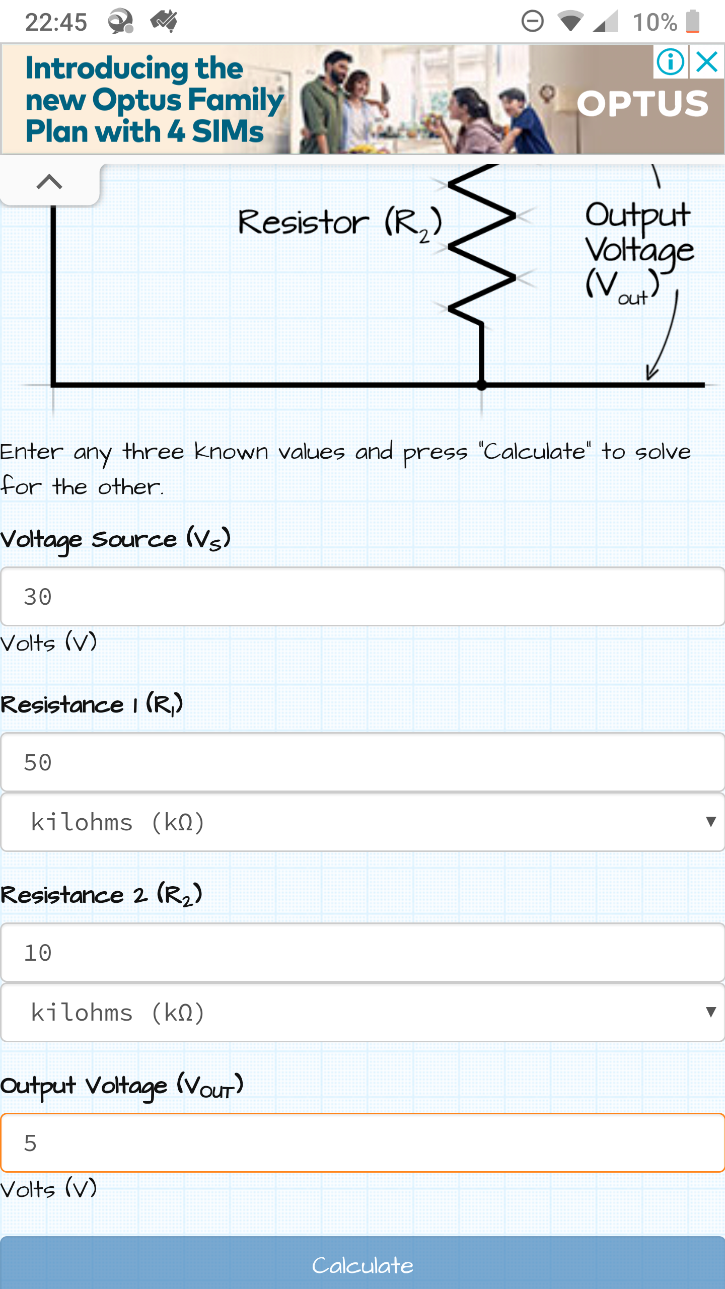
-
Gate controller with Battery Checkerthink i have figured it out
adjusted the math based on another page
Vin = (Pin * 5.0) / 1023;removed the factor of 11 stuff and i think it wasn't necessary?
-
Gate controller with Battery Checker@mfalkvidd you are correct you can do double and it works
-
Gate controller with Battery Checkernow compiles beautifully...
but am getting weird voltage readings... ive just connected a double set of AA batteires and am getting a reading of 11.8-11.9
im using a 100k and a 10k resistor as per this guide.... obviously i stuffed up something in my math....
this always seems to be my way :)
source for voltage reader code
https://www.codrey.com/arduino-projects/nano-digital-volt-meter/ -
Gate controller with Battery Checker@mfalkvidd cheers
ive added that instead but still get the following
call of overloaded 'set(float&)' is ambiguous
-
Gate controller with Battery Checkerfinal bug
when i try to compile the following code
i Get this error
exit status 1
call of overloaded 'set(double&)' is ambiguous googling tells me that my msg need to be defined better for the purpose but im not sure, as i can see in my void that i have declared it as double, but for some reason it doesnt understant that when i go to send my messagevoid batM() { int Pin; // 0-1023 I/P double Vin; Pin = analogRead(A0); // Probe Input Vin = Pin * (5.0*11 / 1023); // Pin to Vin (Reduction Factor 11) Serial.print(Vin); Serial.println(" VOLT DC ");\ send(power.set(Vin)); } -
Gate controller with Battery Checker@Yveaux said in Gate controller with Battery Checker:
wait(15601000ul)
champion that works much better thanks
only one bug left now
-
Gate controller with Battery Checkerhi all
below is my code for a gate controller with attached voltage sensor for measuring the battery supply...
it has a relay and a battery checker and that is allim a little confused to how to change the setup so that the batM loop only runs once every 15 mintues without putitng the sensor to sleep,
i figure i cant put the sensor to sleep as it needs to wait to receive messages from the gateway??
anyone able to advise and let me know if my butchered code can be saved?/** The MySensors Arduino library handles the wireless radio link and protocol between your home built sensors/actuators and HA controller of choice. The sensors forms a self healing radio network with optional repeaters. Each repeater and gateway builds a routing tables in EEPROM which keeps track of the network topology allowing messages to be routed to nodes. Created by Henrik Ekblad <henrik.ekblad@mysensors.org> Copyright (C) 2013-2015 Sensnology AB Full contributor list: https://github.com/mysensors/Arduino/graphs/contributors Documentation: http://www.mysensors.org Support Forum: http://forum.mysensors.org This program is free software; you can redistribute it and/or modify it under the terms of the GNU General Public License version 2 as published by the Free Software Foundation. ******************************* REVISION HISTORY Version 1.0 - Henrik Ekblad Version 1.1 - HenryWhite DESCRIPTION Example sketch showing how to control physical relays. This example will remember relay state after power failure. Optional attachment of motion sensor to control the relays is possible. Notes: -- The Child-IDs of the attached relays range from 1 up to (1-(NUMBER_OF_RELAYS)) -- Make sure to adjust the potentiometer for triggertime on your motion sensor as leftmost as possible, because the countdown will not start until the motion sensor reports back a "0" (no movement) */ //----------------------- Library Configuration --------------------- #define MY_DEBUG // uncomment to enable debug prints to serial monitor #define MY_REPEATER_FEATURE // uncomment to enable repeater functionality for this node // Enable and uncomment attached radio type #define MY_RADIO_RF24 //#define MY_RADIO_RFM69 //#define MY_TRANSPORT_WAIT_READY_MS 1 // uncomment this to enter the loop() and setup()-function even when the node cannot be registered to gw #define NUMBER_OF_RELAYS 1 // Total number of attached relays. Must be equal to total number of elements in array below! const int RELAYS[] = {2}; // digital pins of attached relays const long ON_TIMES[] = {0}; // Specify for each element in MOTION_ACTIVATED_RELAYS, how long the specified relay should be active in seconds. #define RELAY_ON 0 // GPIO value to write to turn on attached relay #define RELAY_OFF 1 // GPIO value to write to turn off attached relay bool ack = 1; // set this to 1 if you want destination node to send ack back to this node #define CHILD_ID_RELAY 1 #define CHILD_ID_VOLTAGE 2 #include <MySensors.h> #include "Wire.h" MyMessage relay_msg; MyMessage power(CHILD_ID_VOLTAGE,V_VOLTAGE); void setup() { } void presentation() { // Send the sketch version information to the gateway and Controller sendSketchInfo("Gate button", "1.0"); present(CHILD_ID_RELAY, S_BINARY); present(CHILD_ID_VOLTAGE, S_MULTIMETER); } void loop() { batM(); } void receive(const MyMessage &message) { // Handle incoming relay commands if (message.type == V_STATUS) { // Change relay state if (RELAYS[message.sensor - 1]) { digitalWrite(RELAYS[message.sensor - 1], message.getBool() ? RELAY_ON : RELAY_OFF); // Store state in eeprom saveState(message.sensor - 1, message.getBool()); // Write some debug info Serial.print("Incoming change for sensor:"); Serial.print(message.sensor); Serial.print(", New status: "); Serial.println(message.getBool()); } } } void relay_msg_constructor(int sensor, uint8_t type) { relay_msg.setSensor(sensor); relay_msg.setType(type); } void batM() { int Pin; // 0-1023 I/P double Vin; Pin = analogRead(A0); // Probe Input Vin = Pin * (5.0*11 / 1023); // Pin to Vin (Reduction Factor 11) Serial.print(Vin); Serial.println(" VOLT DC ");\ send(power); } -
fails to wake with 2 interupts -
fails to wake with 2 interuptshi all im having issue with the follow code...
i have two devices on pin 2 and 3 on a pro mini but cant seem to get wake working one both...
is anyone able to hint/advise on have gone wrong?/* * The MySensors Arduino library handles the wireless radio link and protocol * between your home built sensors/actuators and HA controller of choice. * The sensors forms a self healing radio network with optional repeaters. Each * repeater and gateway builds a routing tables in EEPROM which keeps track of the * network topology allowing messages to be routed to nodes. * * Created by Henrik Ekblad <henrik.ekblad@mysensors.org> * Copyright (C) 2013-2019 Sensnology AB * Full contributor list: https://github.com/mysensors/MySensors/graphs/contributors * * Documentation: http://www.mysensors.org * Support Forum: http://forum.mysensors.org * * This program is free software; you can redistribute it and/or * modify it under the terms of the GNU General Public License * version 2 as published by the Free Software Foundation. * ******************************* * * REVISION HISTORY * Version 1.0 - Henrik Ekblad * * DESCRIPTION * Motion Sensor example using HC-SR501 * http://www.mysensors.org/build/motion * */ // Enable debug prints #define MY_DEBUG // Enable and select radio type attached #define MY_RADIO_RF24 //#define MY_RADIO_NRF5_ESB //#define MY_RADIO_RFM69 //#define MY_RADIO_RFM95 #include <MySensors.h> #include <DallasTemperature.h> #include <OneWire.h> #include <SPI.h> #define COMPARE_TEMP 0 #define MAX_ATTACHED_DS18B20 1 #define DOOR_PIN 3 #define ONE_WIRE_BUS 5 // Pin where dallase sensor is connected OneWire oneWire(ONE_WIRE_BUS); // Setup a oneWire instance to communicate with any OneWire devices (not just Maxim/Dallas temperature ICs) DallasTemperature sensors(&oneWire); // Pass the oneWire reference to Dallas Temperature. float lastTemperature[MAX_ATTACHED_DS18B20]; int numSensors=1; bool receivedConfig = false; bool metric = true; uint32_t SLEEP_TIME = 900000; // Sleep time between reports (in milliseconds) #define DIGITAL_INPUT_SENSOR 2 // The digital input you attached your motion sensor. (Only 2 and 3 generates interrupt!) #define CHILD_ID_MOTION 1 // Id of the sensor child #define CHILD_ID_TEMP 2 #define CHILD_ID_DOOR 3 // Initialize motion message MyMessage motion(CHILD_ID_MOTION, V_TRIPPED); MyMessage temp(CHILD_ID_TEMP,V_TEMP); MyMessage door(CHILD_ID_DOOR,V_TRIPPED); //========================= // BATTERY VOLTAGE DIVIDER SETUP // 1M, 470K divider across battery and using internal ADC ref of 1.1V // Sense point is bypassed with 0.1 uF cap to reduce noise at that point // ((1e6+470e3)/470e3)*1.1 = Vmax = 3.44 Volts // 3.44/1023 = Volts per bit = 0.003363075 #define VBAT_PER_BITS 0.003363075 #define VMIN 1.9 // Vmin (radio Min Volt)=1.9V (564v) #define VMAX 3.0 // Vmax = (2xAA bat)=3.0V (892v) int batteryPcnt = 0; // Calc value for battery % int batLoop = 0; // Loop to help calc average int batArray[3]; // Array to store value for average calc. int BATTERY_SENSE_PIN = A0; // select the input pin for the battery sense point //========================= void before() { // Startup up the OneWire library sensors.begin(); } void setup() { pinMode(DIGITAL_INPUT_SENSOR, INPUT); // sets the motion sensor digital pin as input pinMode(DOOR_PIN, INPUT); // Activate internal pull-up digitalWrite(DOOR_PIN, HIGH); } void presentation() { // Send the sketch version information to the gateway and Controller sendSketchInfo("Front Hall Motion&temp", "1.0"); // Register all sensors to gw (they will be created as child devices) present(CHILD_ID_MOTION, S_MOTION); present(CHILD_ID_TEMP, S_TEMP); present(CHILD_ID_DOOR, S_DOOR); } void loop() { // Read digital motion value bool tripped = digitalRead(DIGITAL_INPUT_SENSOR) == HIGH; Serial.print("Montion Sensor State: "); Serial.println(tripped); send(motion.set(tripped?"1":"0")); // Send tripped value to gw // Sleep until interrupt comes in on motion sensor. Send update every two minute. bool trippeddoor = digitalRead(DOOR_PIN) == HIGH; Serial.print("Door Sensor State: "); Serial.println(trippeddoor); send(door.set(trippeddoor?"1":"0")); // Send tripped value to gw sensors.requestTemperatures(); Serial.print("Temprature: "); Serial.println(sensors.getTempCByIndex(0)); // query conversion time and sleep until conversion completed // sleep() call can be replaced by wait() call if node need to process incoming messages (or if node is repeater) wait(500); // Read temperatures and send them to controller // Fetch and round temperature to one decimal float temperature = sensors.getTempCByIndex(0); // Send in the new temperature send(temp.setSensor(1).set(temperature,1)); // Save new temperatures for next compare batM(); delay(500); sleep(3000); sleep(DIGITAL_INPUT_SENSOR,CHANGE,DOOR_PIN,CHANGE,SLEEP_TIME); } void batM() //The battery calculations { delay(500); // Battery monitoring reading int sensorValue = analogRead(BATTERY_SENSE_PIN); delay(500); // Calculate the battery in % float Vbat = sensorValue * VBAT_PER_BITS; int batteryPcnt = static_cast<int>(((Vbat-VMIN)/(VMAX-VMIN))*100.); Serial.print("Battery percent: "); Serial.print(batteryPcnt); Serial.println(" %"); // Add it to array so we get an average of 3 (3x20min) batArray[batLoop] = batteryPcnt; if (batLoop > 2) { batteryPcnt = (batArray[0] + batArray[1] + batArray[2] + batArray[3]); batteryPcnt = batteryPcnt / 3; if (batteryPcnt > 100) { batteryPcnt=100; } Serial.print("Battery Average (Send): "); Serial.print(batteryPcnt); Serial.println(" %"); sendBatteryLevel(batteryPcnt); batLoop = 0; } else { batLoop++; } } -
temp sensor not reading at all -
temp sensor not reading at allok think i have partially found the issue, when i re did it for a simpler setup, it seems that im measureing temprature of -127 im not even sure what the means, i assume its an error but not sure what its telling me
-
temp sensor not reading at all -
temp sensor not reading at allhey guys
ive tried to modify two of the built in designs to make them work together, but i think ive stuffed up the dallas temprature probethe temprature is never updated or sent to the controller
anyone able to advise what ive missed?
i only have the one temprature sensor hooked up// Enable debug prints //#define MY_DEBUG // Enable and select radio type attached #define MY_RADIO_RF24 //#define MY_RADIO_RFM69 #include <MySensors.h> #include <DallasTemperature.h> #include <OneWire.h> #define COMPARE_TEMP 1 #define MAX_ATTACHED_DS18B20 16 #define LIGHT_SENSOR_ANALOG_PIN 0 #define ONE_WIRE_BUS 3 // Pin where dallase sensor is connected OneWire oneWire(ONE_WIRE_BUS); // Setup a oneWire instance to communicate with any OneWire devices (not just Maxim/Dallas temperature ICs) DallasTemperature sensors(&oneWire); // Pass the oneWire reference to Dallas Temperature. float lastTemperature[MAX_ATTACHED_DS18B20]; int numSensors=0; bool receivedConfig = false; bool metric = true; unsigned long SLEEP_TIME = 120000 ; // 120000 Sleep time between reports (in milliseconds) int lastLightLevel; #define CHILD_ID_TEMP 1 #define CHILD_ID_LIGHT 2 // Enable repeater functionality for this node //#define MY_REPEATER_FEATURE // Initialize motion message MyMessage temp(CHILD_ID_TEMP,V_TEMP); MyMessage light(CHILD_ID_LIGHT, V_LIGHT_LEVEL); //========================= // BATTERY VOLTAGE DIVIDER SETUP // 1M, 470K divider across battery and using internal ADC ref of 1.1V // Sense point is bypassed with 0.1 uF cap to reduce noise at that point // ((1e6+470e3)/470e3)*1.1 = Vmax = 3.44 Volts // 3.44/1023 = Volts per bit = 0.003363075 #define VBAT_PER_BITS 0.003363075 #define VMIN 1.9 // Vmin (radio Min Volt)=1.9V (564v) #define VMAX 3.0 // Vmax = (2xAA bat)=3.0V (892v) int batteryPcnt = 0; // Calc value for battery % int batLoop = 0; // Loop to help calc average int batArray[3]; // Array to store value for average calc. int BATTERY_SENSE_PIN = A0; // select the input pin for the battery sense point //========================= void before() { // Startup up the OneWire library sensors.begin(); } void setup() { sensors.setWaitForConversion(false); numSensors = sensors.getDeviceCount(); } void presentation() { // Send the sketch version information to the gateway and Controller sendSketchInfo("Lounge Node enviroment", "1.0"); // Register all sensors to gw (they will be created as child devices) present(CHILD_ID_LIGHT, S_LIGHT_LEVEL); present(CHILD_ID_TEMP, S_TEMP); } void loop() { //light sensor int16_t lightLevel = (1023-analogRead(LIGHT_SENSOR_ANALOG_PIN))/10.23; Serial.print("Light Level:"); Serial.println(lightLevel); if (lightLevel != lastLightLevel) { send(light.set(lightLevel)); lastLightLevel = lightLevel; //temprature sensors.requestTemperatures(); // query conversion time and sleep until conversion completed int16_t conversionTime = sensors.millisToWaitForConversion(sensors.getResolution()); // sleep() call can be replaced by wait() call if node need to process incoming messages (or if node is repeater) sleep(conversionTime); // Read temperatures and send them to controller for (int i=0; i<numSensors && i<MAX_ATTACHED_DS18B20; i++) { // Fetch and round temperature to one decimal float temperature = static_cast<float>(static_cast<int>((getControllerConfig().isMetric?sensors.getTempCByIndex(i):sensors.getTempFByIndex(i)) * 10.)) / 10.; // Only send data if temperature has changed and no error #if COMPARE_TEMP == 1 if (lastTemperature[i] != temperature && temperature != -127.00 && temperature != 85.00) { #else if (temperature != -127.00 && temperature != 85.00) { #endif // Send in the new temperature send(temp.setSensor(i).set(temperature,1)); // Save new temperatures for next compare lastTemperature[i]=temperature; } } batM(); // Sleep until interrupt comes in on motion sensor. Send update every two minute. sleep(SLEEP_TIME); } } void batM() //The battery calculations { delay(500); // Battery monitoring reading int sensorValue = analogRead(BATTERY_SENSE_PIN); delay(500); // Calculate the battery in % float Vbat = sensorValue * VBAT_PER_BITS; int batteryPcnt = static_cast<int>(((Vbat-VMIN)/(VMAX-VMIN))*100.); Serial.print("Battery percent: "); Serial.print(batteryPcnt); Serial.println(" %"); // Add it to array so we get an average of 3 (3x20min) batArray[batLoop] = batteryPcnt; if (batLoop > 2) { batteryPcnt = (batArray[0] + batArray[1] + batArray[2] + batArray[3]); batteryPcnt = batteryPcnt / 3; if (batteryPcnt > 100) { batteryPcnt=100; } Serial.print("Battery Average (Send): "); Serial.print(batteryPcnt); Serial.println(" %"); sendBatteryLevel(batteryPcnt); batLoop = 0; } else { batLoop++; } } -
NRF24L01+ and NRF24L01+PA-LNA problems - testing in progress@wiredfrank 100% agree. Dodgy antennas have been the bane of my existence with mysensors. When needing the long range. DO. NOT. CHEAP. OUT.
-
Simple irrigation controllerhey @Tmaster
are you still using this solution?
have you made any improvements or come across any issues with using it over time?