And my settings are seen in previous posts.
But this does not lead to anything so I finish this now.
M
MLs
@MLs
Posts
-
Another simple (No SMT) relay actuator -
Another simple (No SMT) relay actuatorI can burn Mysbootloader yes.
But the Atmega circuit does not start.
The problem I think is that Mysbootloader does not use the internal clockAnd because you said you had a bootloader for OTA and internal clock, 8MHz I wanted you to send it to me.
Then there would have been no problem, I think.
-
Another simple (No SMT) relay actuator@MLs said in Another simple (No SMT) relay actuator:
@MLs said in Another simple (No SMT) relay actuator:
Feeling a bit confused how do you know that a bootloader uses the internal clock?
Because I used another bootloader after installing your card, I did not get the Atmega circuit to run. But if I used this bootloader, I started the Atmega circuit and everything worked.But what makes the internal clock in used?
I use a UNO when I'm burning bootloader and do not know if you can change fuses and clock option.If you use a bootloader that uses an external clock, you will not get the Atmega circuit to run. If I understand everything right.
No if I'm burning 8MHz Mysbootloader, the Atmega circuit does not start.
But instead, I use this bootloader (ATmega328 on a 8 MHz internal clock) and I get the Atmega circuit to run, but without OTA.
Therefore, I asked you how to know how a bootloader uses an external clock or internal clock.
-
Another simple (No SMT) relay actuator@MLs said in Another simple (No SMT) relay actuator:
Feeling a bit confused how do you know that a bootloader uses the internal clock?
Because I used another bootloader after installing your card, I did not get the Atmega circuit to run. But if I used this bootloader, I started the Atmega circuit and everything worked.But what makes the internal clock in used?
I use a UNO when I'm burning bootloader and do not know if you can change fuses and clock option.If you use a bootloader that uses an external clock, you will not get the Atmega circuit to run. If I understand everything right.
No if I'm burning 8MHz Mysbootloader, the Atmega circuit does not start.
But instead, I use this bootloader (ATmega328 on a 8 MHz internal clock) and I get the Atmega circuit to run, but without OTA.
-
Another simple (No SMT) relay actuatorThe problem is not to burn bootloader. The problem I think is that the Mysbootloader does not use internal clock.
Therefore, I asked you how to know how a bootloader uses an external clock or internal clock.
And because you had a bootloader for OTA and internal clock, 8MHz I wanted you to send it to me. -
Another simple (No SMT) relay actuator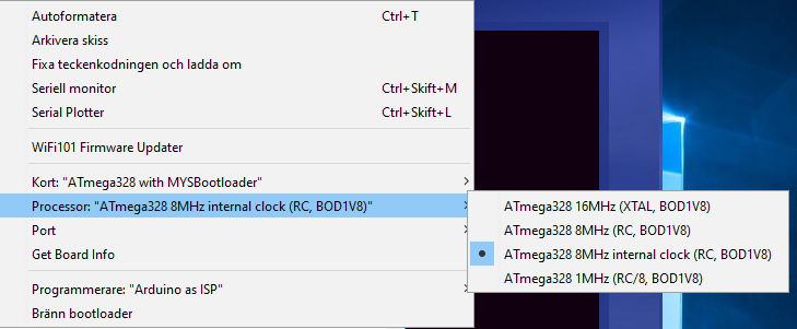
############################################################## MYSBL13.name=ATmega328 with MYSBootloader MYSBL13.upload.tool=avrdude MYSBL13.upload.protocol=arduino MYSBL13.bootloader.tool=avrdude MYSBL13.bootloader.unlock_bits=0x3F MYSBL13.bootloader.lock_bits=0x0F MYSBL13.build.mcu=atmega328p MYSBL13.build.board=AVR_PRO MYSBL13.build.core=arduino MYSBL13.build.variant=standard ## Arduino with MYSBootloader 1.3pre ## ------------------------------------------------- MYSBL13.menu.cpu.16MHzatmega328=ATmega328 16MHz (XTAL, BOD1V8) MYSBL13.menu.cpu.16MHzatmega328.upload.maximum_size=30720 MYSBL13.menu.cpu.16MHzatmega328.upload.maximum_data_size=2048 MYSBL13.menu.cpu.16MHzatmega328.upload.speed=115200 MYSBL13.menu.cpu.16MHzatmega328.bootloader.low_fuses=0xFF MYSBL13.menu.cpu.16MHzatmega328.bootloader.high_fuses=0xDA MYSBL13.menu.cpu.16MHzatmega328.bootloader.extended_fuses=0x06 MYSBL13.menu.cpu.16MHzatmega328.bootloader.file=MYSBootloader/MYSBL13pre_atmega328_16Mhz.hex MYSBL13.menu.cpu.16MHzatmega328.build.mcu=atmega328p MYSBL13.menu.cpu.16MHzatmega328.build.f_cpu=16000000L MYSBL13.menu.cpu.8MHzatmega328=ATmega328 8MHz (RC, BOD1V8) MYSBL13.menu.cpu.8MHzatmega328.upload.maximum_size=30720 MYSBL13.menu.cpu.8MHzatmega328.upload.maximum_data_size=2048 MYSBL13.menu.cpu.8MHzatmega328.upload.speed=38400 MYSBL13.menu.cpu.8MHzatmega328.bootloader.low_fuses=0xE2 MYSBL13.menu.cpu.8MHzatmega328.bootloader.high_fuses=0xDA MYSBL13.menu.cpu.8MHzatmega328.bootloader.extended_fuses=0x06 MYSBL13.menu.cpu.8MHzatmega328.bootloader.file=MYSBootloader/MYSBL13pre_atmega328_8Mhz.hex MYSBL13.menu.cpu.8MHzatmega328.build.mcu=atmega328p MYSBL13.menu.cpu.8MHzatmega328.build.f_cpu=8000000L ############# DO NOT WORK INTERNAL CLOCK ##################### MYSBL13.menu.cpu.8MHzinternalclockatmega328=ATmega328 8MHz internal clock (RC, BOD1V8) MYSBL13.menu.cpu.8MHzinternalclockatmega328.upload.maximum_size=30720 MYSBL13.menu.cpu.8MHzinternalclockatmega328.upload.maximum_data_size=2048 MYSBL13.menu.cpu.8MHzinternalclockatmega328.upload.speed=38400 MYSBL13.menu.cpu.8MHzinternalclockatmega328.upload.tool=arduino:avrdude MYSBL13.menu.cpu.8MHzinternalclockatmega328.upload.protocol=arduino MYSBL13.menu.cpu.8MHzinternalclockatmega328.bootloader.low_fuses=0xE2 MYSBL13.menu.cpu.8MHzinternalclockatmega328.bootloader.high_fuses=0xDA MYSBL13.menu.cpu.8MHzinternalclockatmega328.bootloader.extended_fuses=0xfe MYSBL13.menu.cpu.8MHzinternalclockatmega328.bootloader.file=breadboard/MYSBL13pre_atmega328_8Mhz.hex MYSBL13.menu.cpu.8MHzinternalclockatmega328.bootloader.unlock_bits=0x3F MYSBL13.menu.cpu.8MHzinternalclockatmega328.bootloader.lock_bits=0x0F MYSBL13.menu.cpu.8MHzinternalclockatmega328.bootloader.tool=arduino:avrdude MYSBL13.menu.cpu.8MHzinternalclockatmega328.build.mcu=atmega328p MYSBL13.menu.cpu.8MHzinternalclockatmega328.build.f_cpu=8000000L MYSBL13.menu.cpu.8MHzinternalclockatmega328.build.core=arduino:arduino MYSBL13.menu.cpu.8MHzinternalclockatmega328.build.variant=arduino:standard MYSBL13.menu.cpu.1MHzatmega328=ATmega328 1MHz (RC/8, BOD1V8) MYSBL13.menu.cpu.1MHzatmega328.upload.maximum_size=30720 MYSBL13.menu.cpu.1MHzatmega328.upload.maximum_data_size=2048 MYSBL13.menu.cpu.1MHzatmega328.upload.speed=9600 MYSBL13.menu.cpu.1MHzatmega328.bootloader.low_fuses=0x62 MYSBL13.menu.cpu.1MHzatmega328.bootloader.high_fuses=0xDA MYSBL13.menu.cpu.1MHzatmega328.bootloader.extended_fuses=0x06 MYSBL13.menu.cpu.1MHzatmega328.bootloader.file=MYSBootloader/MYSBL13pre_atmega328_1Mhz.hex MYSBL13.menu.cpu.1MHzatmega328.build.mcu=atmega328p MYSBL13.menu.cpu.1MHzatmega328.build.f_cpu=1000000L ##############################################################``` -
Another simple (No SMT) relay actuatorI do not get Atmel to run with Mysbootloader 8MHz.
Seems like it does not use the internal clock
Also tried to put your text into the board.txt file without any difference.
But if I use the bottloader ATmega328 on a breadboard (8 MHz internal clock it work. -
Another simple (No SMT) relay actuator@dpressle
Ok first, I have to say that I have no problem getting your project to work. It connects directly to HA. What I get a little confused about is that according to the link I linked to it says.Be sure to select "ATmega328 on a breadboard (8 MHz internal clock)" when burning the bootloader.(If you select the wrong item and configure the microcontroller to use an external clock, it won't work unless you connect one.)
And as I interpret your post, you can take whatever bootloader you want (8 MHz).
And if I understand you right now, all settings iis n the board.txt file?//Mattias
-
Another simple (No SMT) relay actuatorFeeling a bit confused how do you know that a bootloader uses the internal clock?
Because I used another bootloader after installing your card, I did not get the Atmega circuit to run. But if I used this bootloader, I started the Atmega circuit and everything worked.But what makes the internal clock in used?
I use a UNO when I'm burning bootloader and do not know if you can change fuses and clock option. -
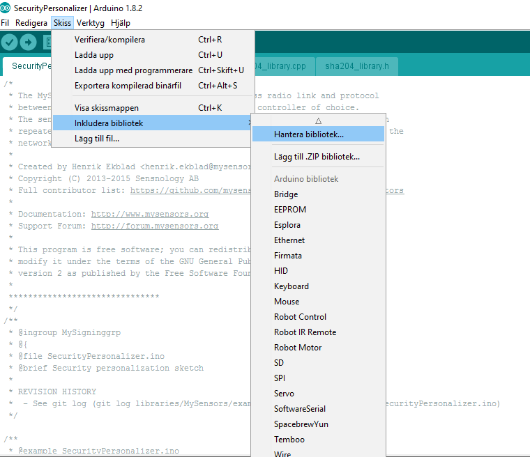
My sensors 2.1.1It depends a little on what you want to do, but at first it is enough. However, if you want to use MySensor's example using external libraries, you will also need to download this link.
Https://github.com/mysensors/MySensorsArduinoExamples/archive/master.zipFor example, DHT 22, which measures temperature and humidity.
//Mattias
-
Another simple (No SMT) relay actuator -
Another simple (No SMT) relay actuator -
Another simple (No SMT) relay actuator -
My sensors 2.1.1What version do you have of IDE? In newer versions, you install the MySensors library in IDE
//Mattias
-
MYSBootloader 1.3Something new about OTA and MySensors 2.1.1 with atmega328P-PU 28 DIP 8MHz internal clock?
//Mattias
-
Another simple (No SMT) relay actuatorWhere can you find the code?
-
Can't ping Ethernet Gateway ENC28J60 + Arduino Nano CloneI'm no expert but I would have looked at the data sheet and measured up to make sure that the hardware are not defective in any way.
http://ww1.microchip.com/downloads/en/DeviceDoc/39662c.pdf
Or the radio.
//Mattias
-
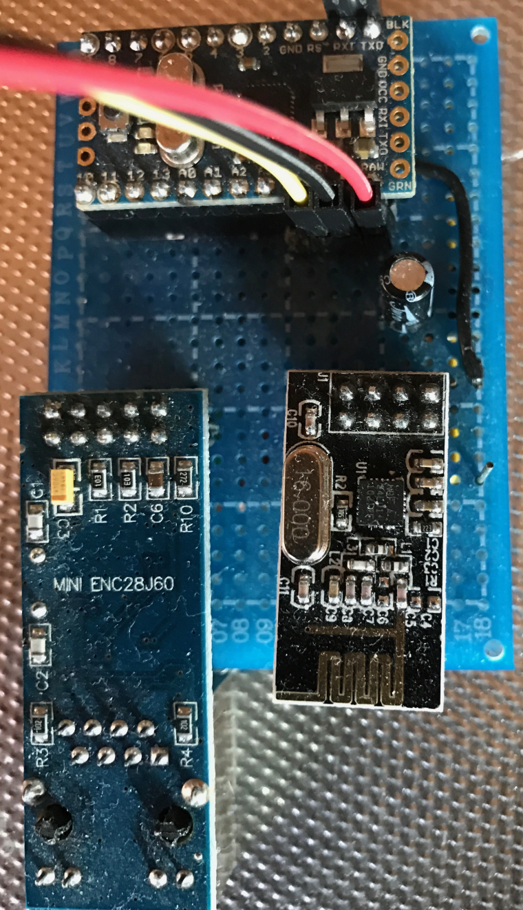
Can't ping Ethernet Gateway ENC28J60 + Arduino Nano CloneThere I can say is that the circuit ENC28J60 works with MySensors lib 2.1.1
Try to connect your components to breadboard. -
Can't ping Ethernet Gateway ENC28J60 + Arduino Nano CloneOk, you have linked NRF24 radio right?
https://www.mysensors.org/build/ethernet_gateway#enc28j60-ethernet-module
Also verified that the shield is properly attached?
//Mattias -
Can't ping Ethernet Gateway ENC28J60 + Arduino Nano Clone