Which are the *best* NRF24L01+ modules?
-
@NeverDie said:
I don't see a way to PM you with my email address, as it doesn't look as though this forum supports private messaging.
Just click on a avatar and press the "Chat" button. The messages is stored just like old-style PM.
@hek said:
@NeverDie said:
I don't see a way to PM you with my email address, as it doesn't look as though this forum supports private messaging.
Just click on a avatar and press the "Chat" button. The messages is stored just like old-style PM.
Thanks for explaining that. As a result, I just sent Jerry my contact info that way.
-
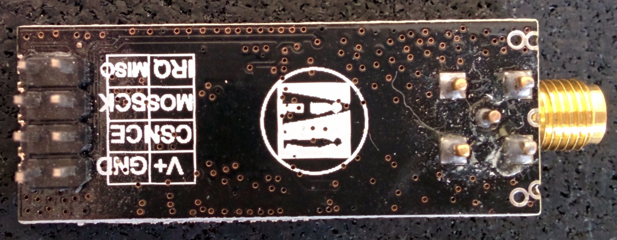
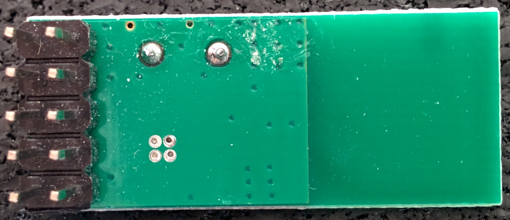
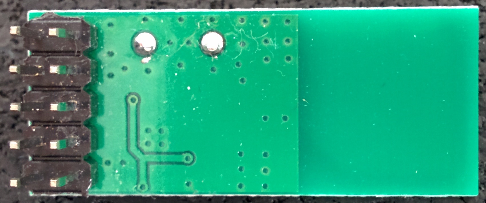
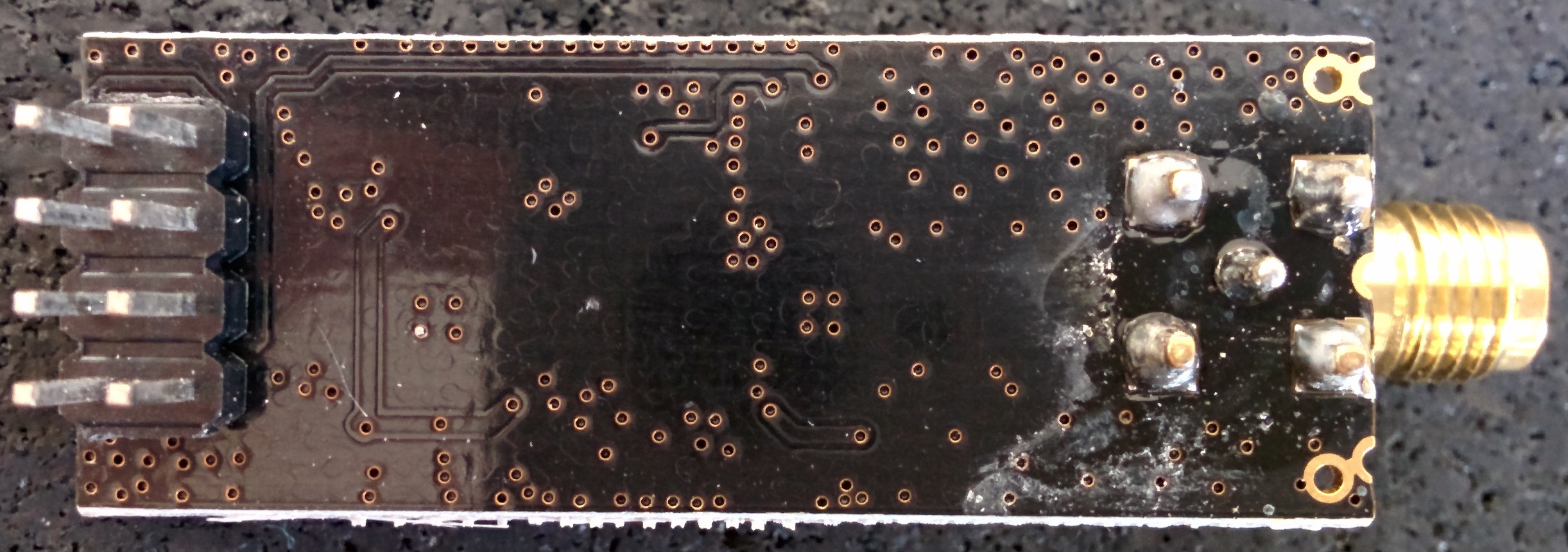
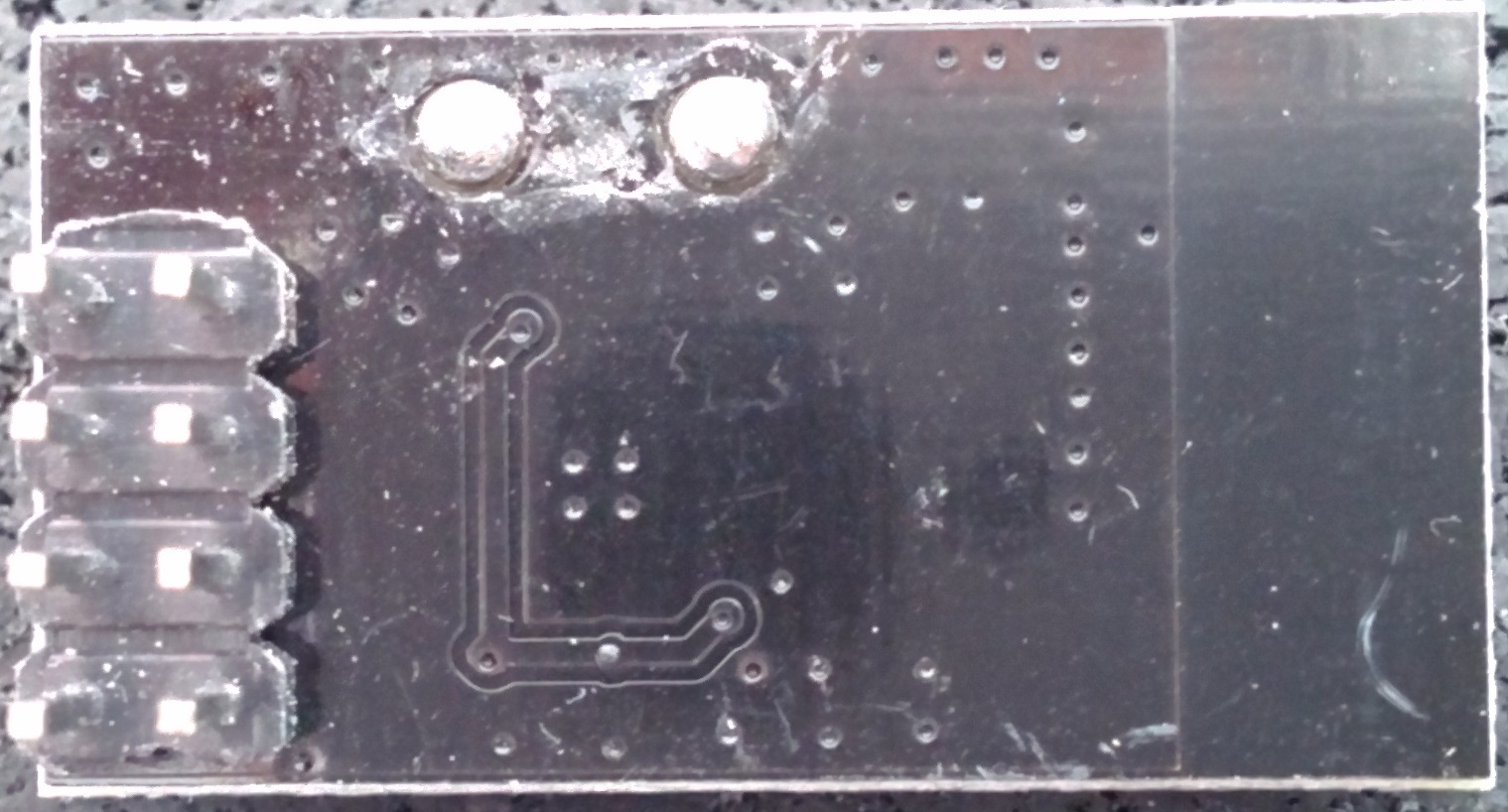
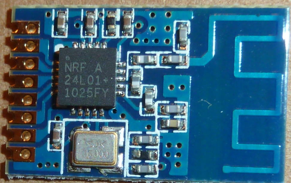
An overview of the module I have lying around (origin is unclear, as I don't really keep track of where they come from)
The chip close-ups were taken using a microscope, so they have far higher resolution then shown in the table (right-click & show image to view at native resolution) .Datecode YYWWLL Module top Module bottom Closeup Fake/Genuine 0830AE 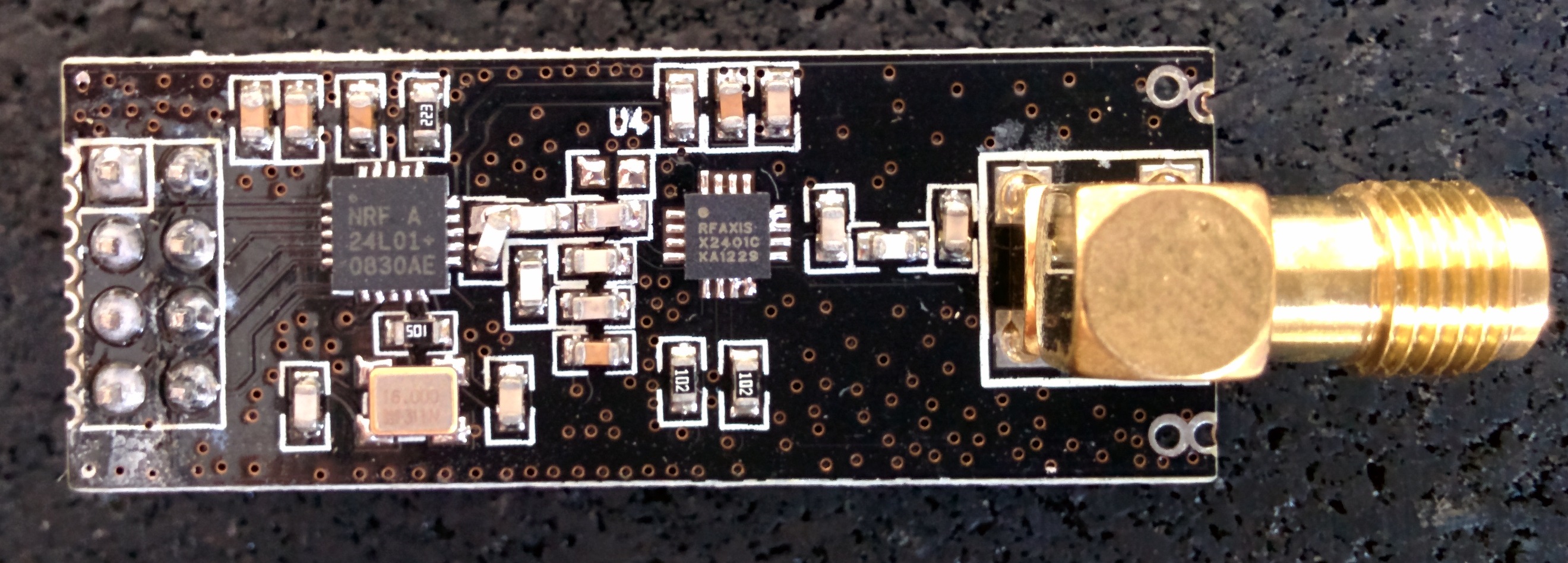
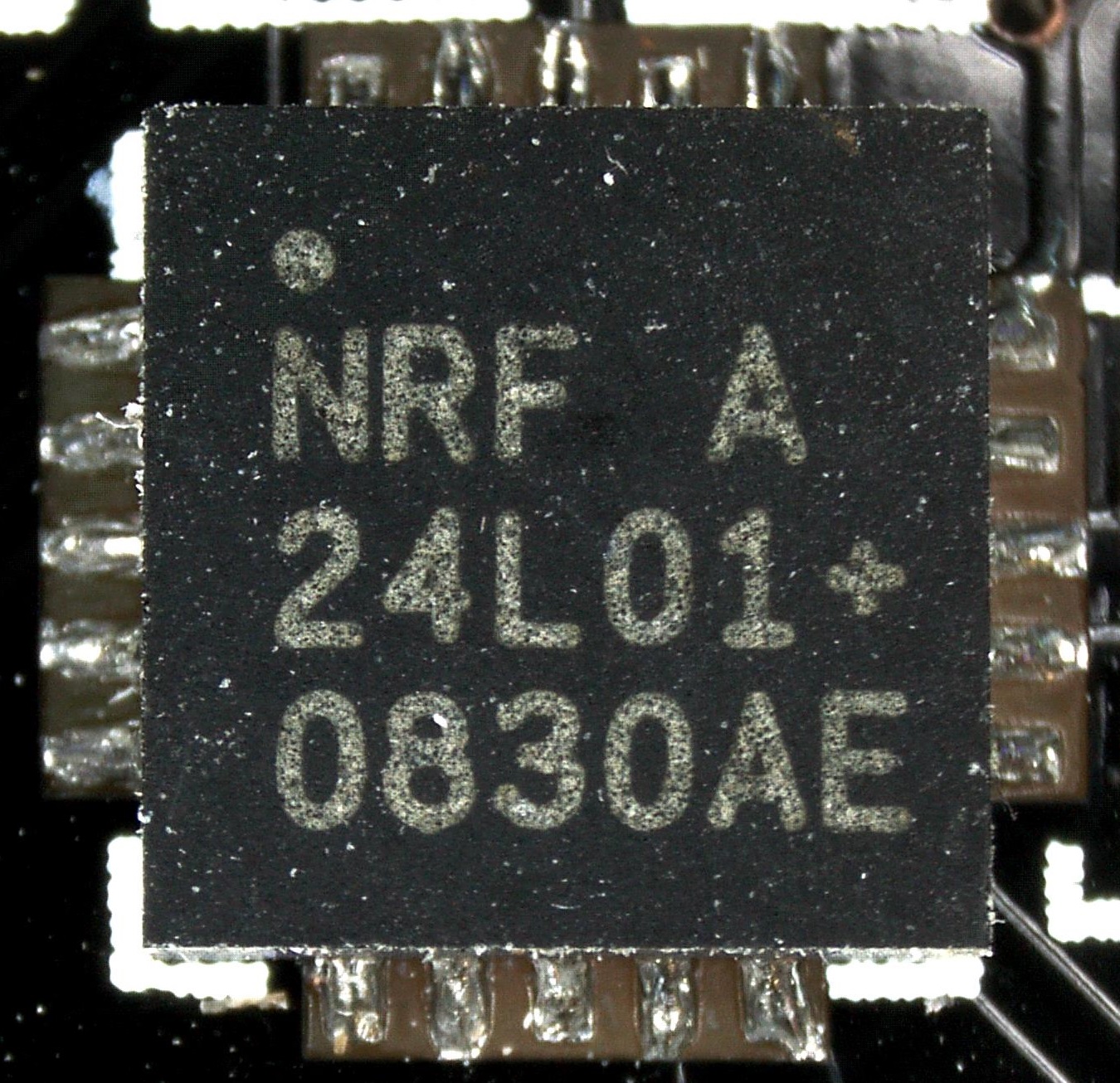
Genuine? Datecode 0830 indicates production wk30 2008. nRF24L01+ was launched in 2008 1242AF 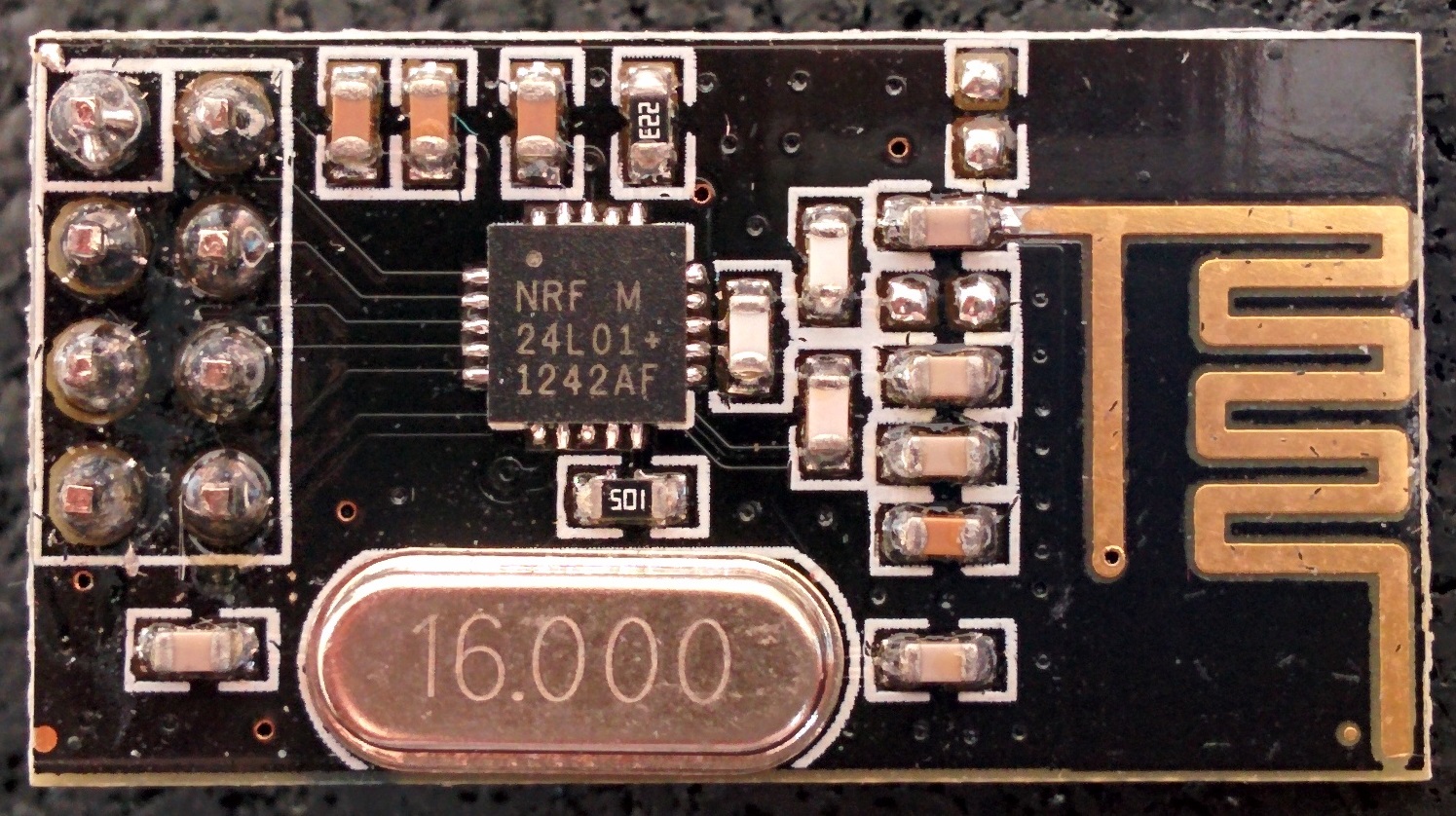
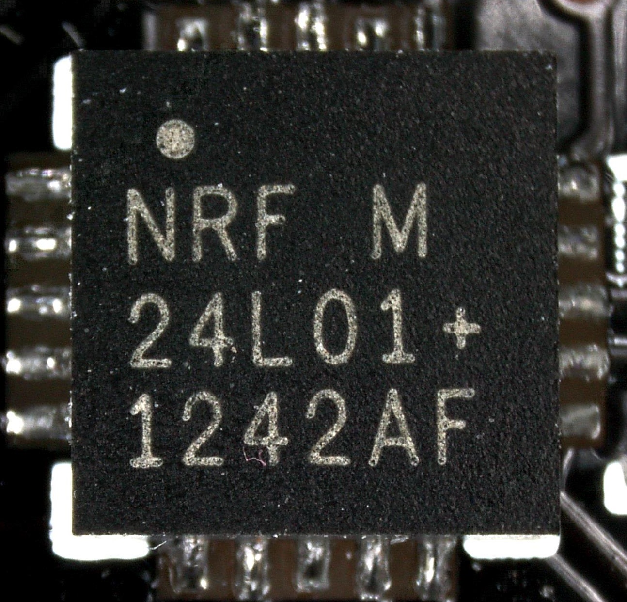
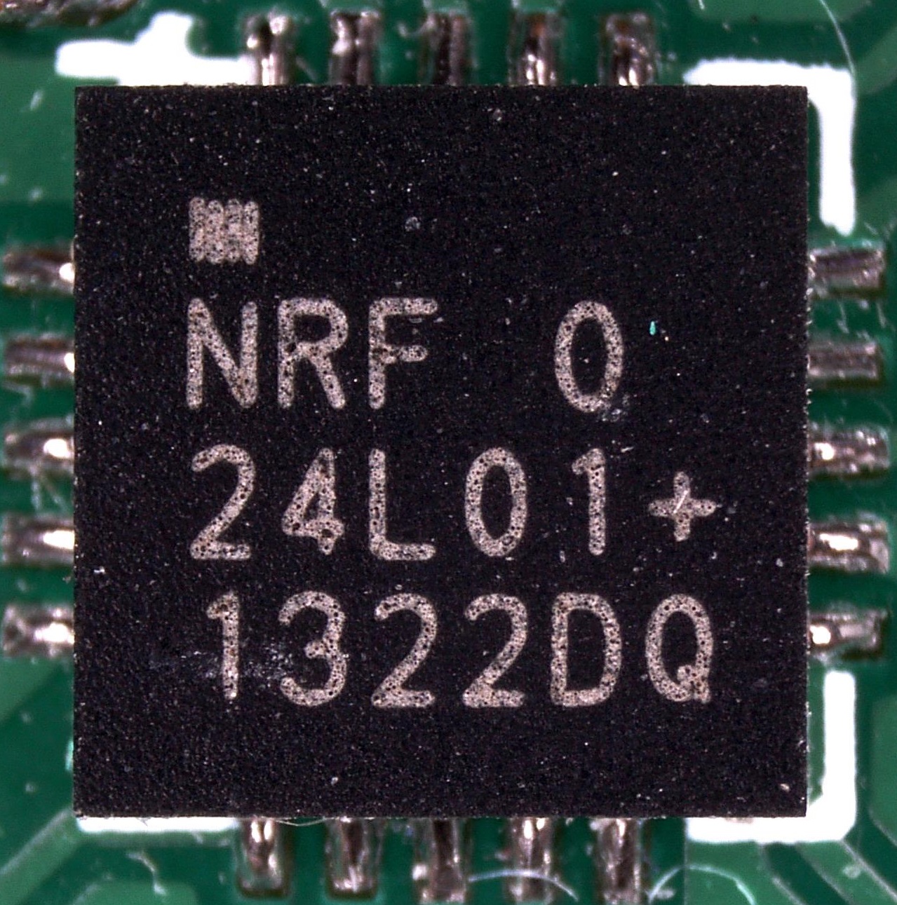
Known counterfeit, according to this 1322DQ 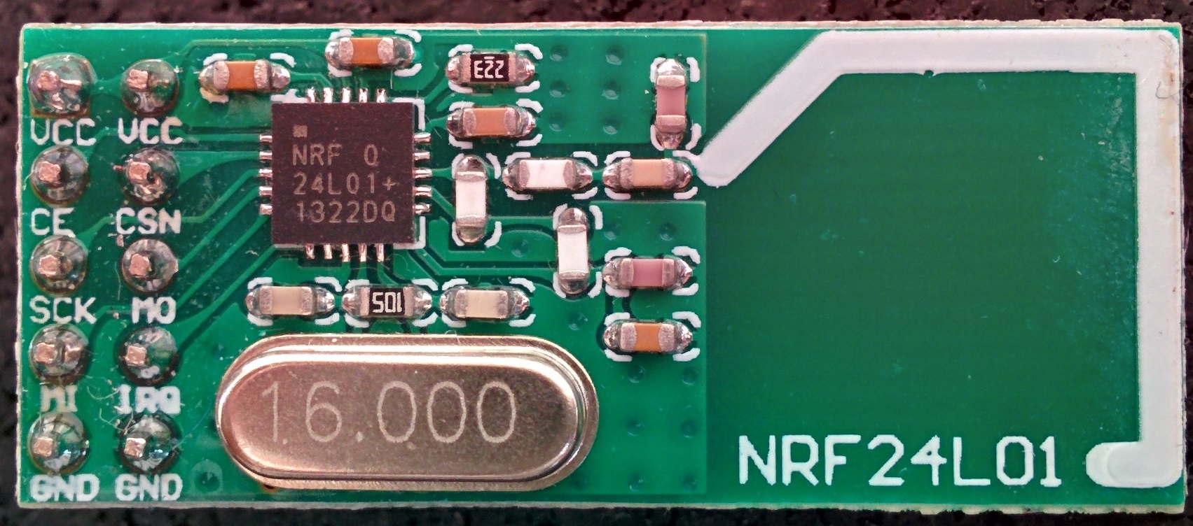
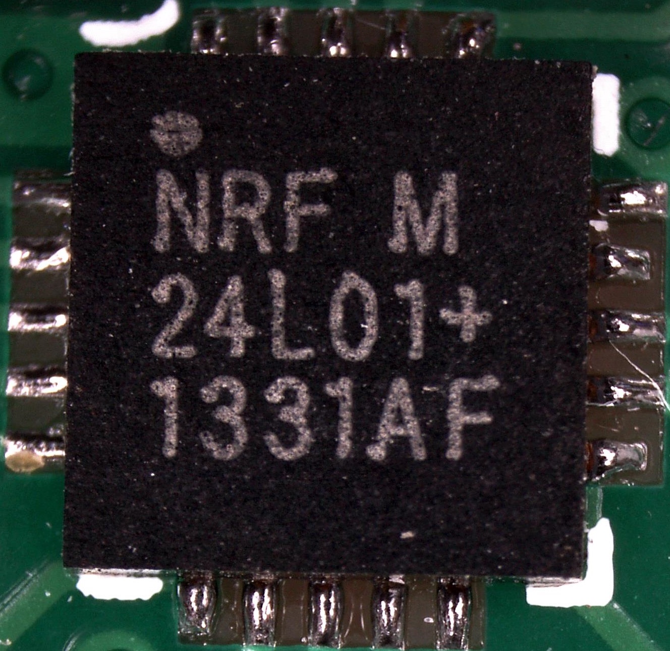
1331AF 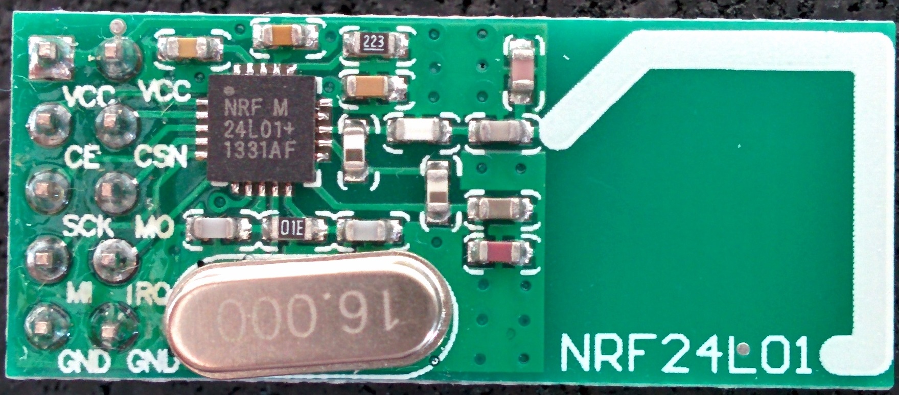
Known counterfeit, according to this 1405FJ 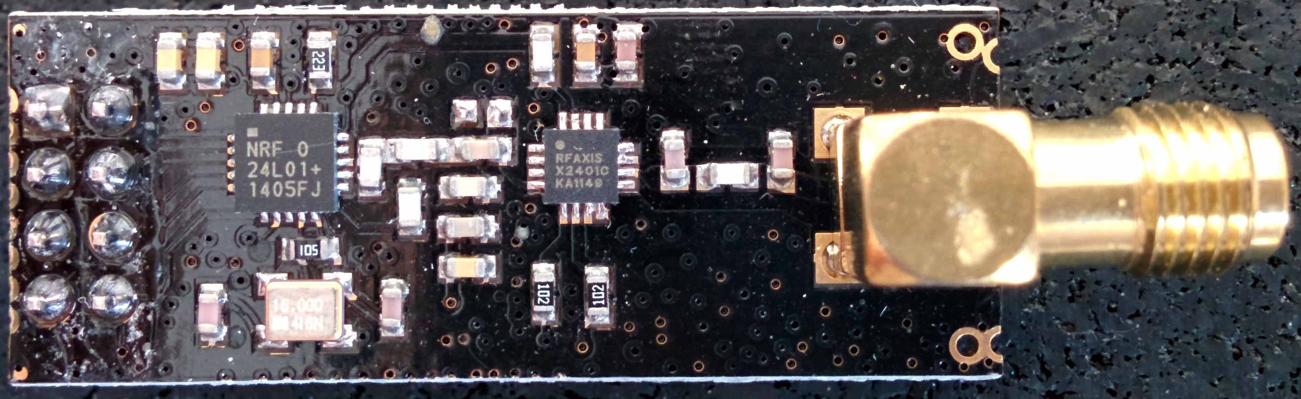
1408AF 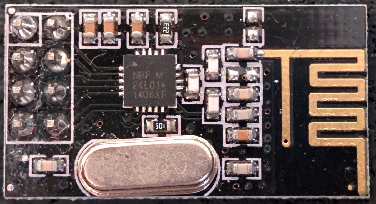
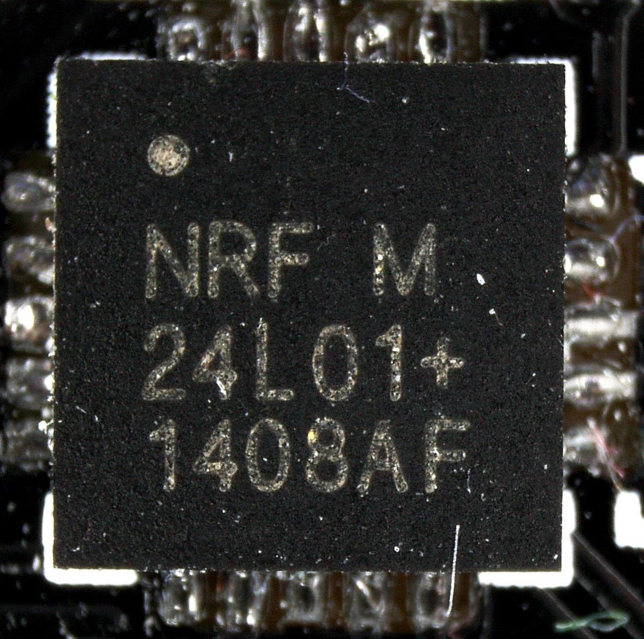
Probably fake (identical to left one bottom of the page -
@NeverDie I do not use capacitors but I have noticed that the quality of the power supply is important but USB from a computer should have very little noise so that is not the reason.
If you happen to have capacitors, would be interesting to see how they effect the results.
@hek (or anyone else who knows what they are doing), as this seems to be a universal problem, why don't you start a github sketch with simple regression results that will evolve with time? we can also start a google drive spreadsheet to collect the results so we can record who we bought it from, include a photo and the results. Although the Chinese merchants can be fickle with they supply chain, at least on aliexpress you can verify beforehand with them that you are getting specific things and if you get something else you just don't pay. It is possible to establish good and reliable supply with them if they see that it brings them consistent returns and rating - I have done that with components for my LED lights. But we need a simple way of telling what we get....@Moshe-Livne said:
why don't you start a github sketch with simple regression results that will evolve with time?
I'm thinking about a simple sketch, based of the nRF24 Sniffer's code, which connects two radios and checks on air how a radio communicates. This should allow detecting the inverted NO_ACK bit (see Jay Tyzzer's comment here) to immediately quilify a module as fake when detected.
Of course this doesn't mean it's genuine when doesn't have the bit inverted, but the sketch could also dump register settings to be able to detect a pattern. -
Great pictures! What microscope are you using?
I can't see anyone having the hole in the +-sign...
-
Great pictures! What microscope are you using?
I can't see anyone having the hole in the +-sign...
-
@Moshe-Livne said:
why don't you start a github sketch with simple regression results that will evolve with time?
I'm thinking about a simple sketch, based of the nRF24 Sniffer's code, which connects two radios and checks on air how a radio communicates. This should allow detecting the inverted NO_ACK bit (see Jay Tyzzer's comment here) to immediately quilify a module as fake when detected.
Of course this doesn't mean it's genuine when doesn't have the bit inverted, but the sketch could also dump register settings to be able to detect a pattern.@Yveaux wonderful! Even if fake, ones with correct ack bit will probably work better so its a step in the right direction
-
An overview of the module I have lying around (origin is unclear, as I don't really keep track of where they come from)
The chip close-ups were taken using a microscope, so they have far higher resolution then shown in the table (right-click & show image to view at native resolution) .Datecode YYWWLL Module top Module bottom Closeup Fake/Genuine 0830AE Genuine? Datecode 0830 indicates production wk30 2008. nRF24L01+ was launched in 2008 1242AF Known counterfeit, according to this 1322DQ 1331AF Known counterfeit, according to this 1405FJ 1408AF Probably fake (identical to left one bottom of the page @Yveaux said:
An overview of the module I have lying around (origin is unclear, as I don't really keep track of where they come from)
The chip close-ups were taken using a microscope, so they have far higher resolution then shown in the table (right-click & show image to view at native resolution) .Datecode YYWWLL Module top Module bottom Closeup Fake/Genuine 0830AE Genuine? Datecode 0830 indicates production wk30 2008. nRF24L01+ was launched in 2008 FWIW, the 0830AE date code is only a little earlier (4 weeks?) than the 0834AF datecode on the chip above in Hek's post where Hek alleges the module is genuine.
-
@Yveaux said:
I really needed it to hand-solder those QFN's ;-)
How hard would it be to desolder a bogus NRF chip and then solder a known good NRF24L01+ (purchased either directly from Nordic, if Nordic does that, or else from a trusted distributor like Digikey) in its place? Perhaps in this way the modules can be given a second life of sorts.
-
@Yveaux: Those are wonderful photos! Thanks so much for posting them. :smile: Did you use the microscope for the module shots also, or just the NRF chip closeups?
Since you have a nice module collection that spans different NRF chips and also different module types, have you noticed whether any of your modules stand out head-and-shoulders above the others as having clearly better performance?
-
Lol, I just checked all of my radios from Alice1101983 and they are all dated 1242AF - FAKES! I have 20 from two orders of 10 radios each placed about six months apart (10/14 & 4/15) and they all have the same production date. They do work but I have occasional and random node hangup. This is an ongoing problem which I have been unable to troubleshoot. @hek, we might want to change the vendor in the MySensors store.
-
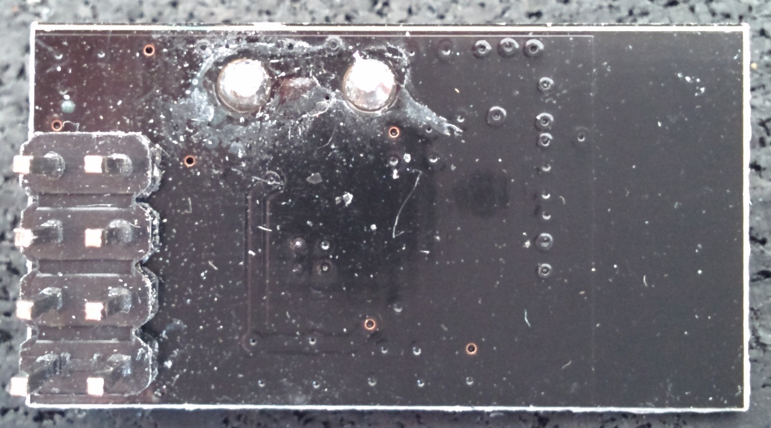
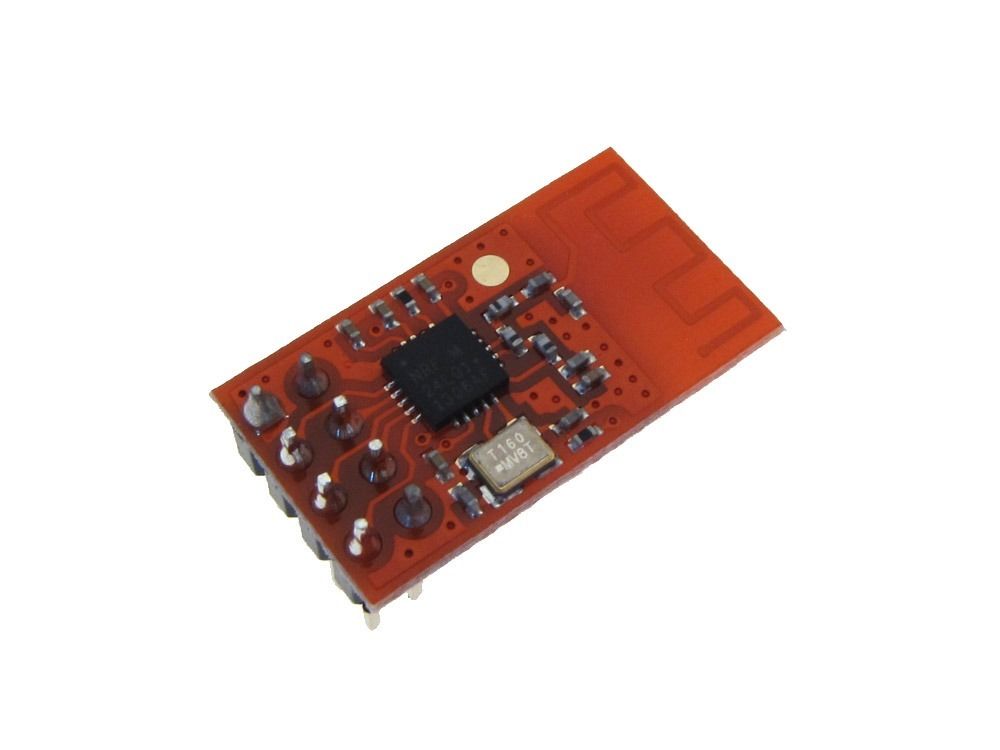
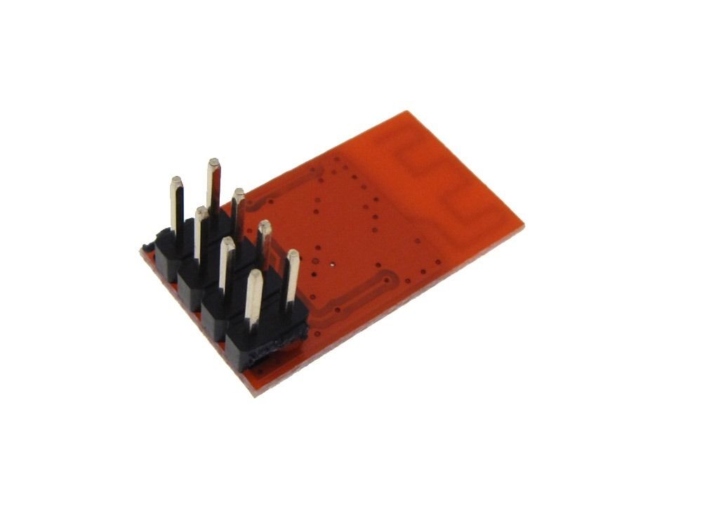
Here's a module that is itself surface mountable. It seems like roughly half the footprint of typical modules.
Anyone have suggestions on how best to cheaply hook it up to an arduino? Not sure, but the pin pitch might be 1.27mm. I do have arduino prototyping shields, and there do seem to be 7 pin areas meant for soldering on something with surface mount (see SOIC area in upper left below):
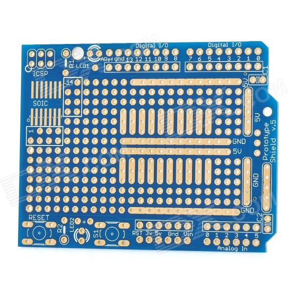
Unfortunately, there are only 7 pads on the SOIC that I can solder it to, and the ground pin is on the end, with the IRQ next to it.
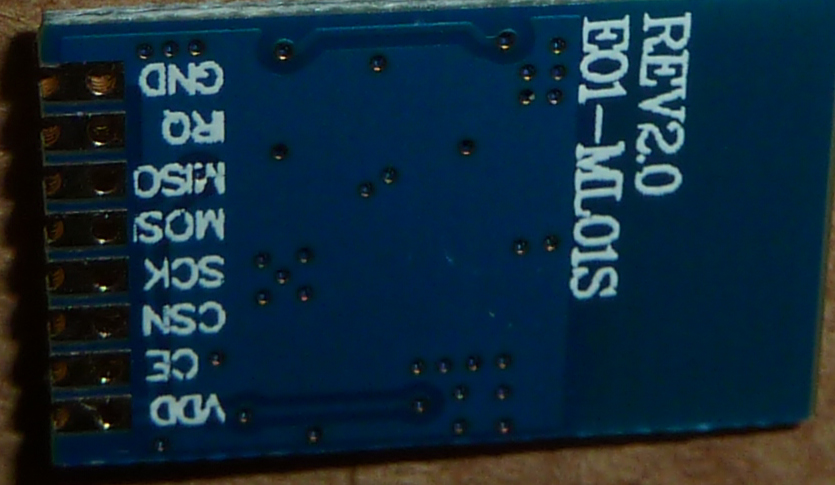
Not ideal! Should I try soldering a wire to the ground pin but solder the rest of the pins to the SOIC pads on the prototyping board? Seems like that may be the cleanest way to do it.That might be fine if using an Uno, but what about if using a pro mini? How best to connect it then? Anyone here already doing it?
As a ghetto method I could also run jumper pins through each through-hole and solder into place, and then run each wire to the proper pin on the pro mini and solder into place, but... not very elegant. Are there better ways I'm not aware of?
-
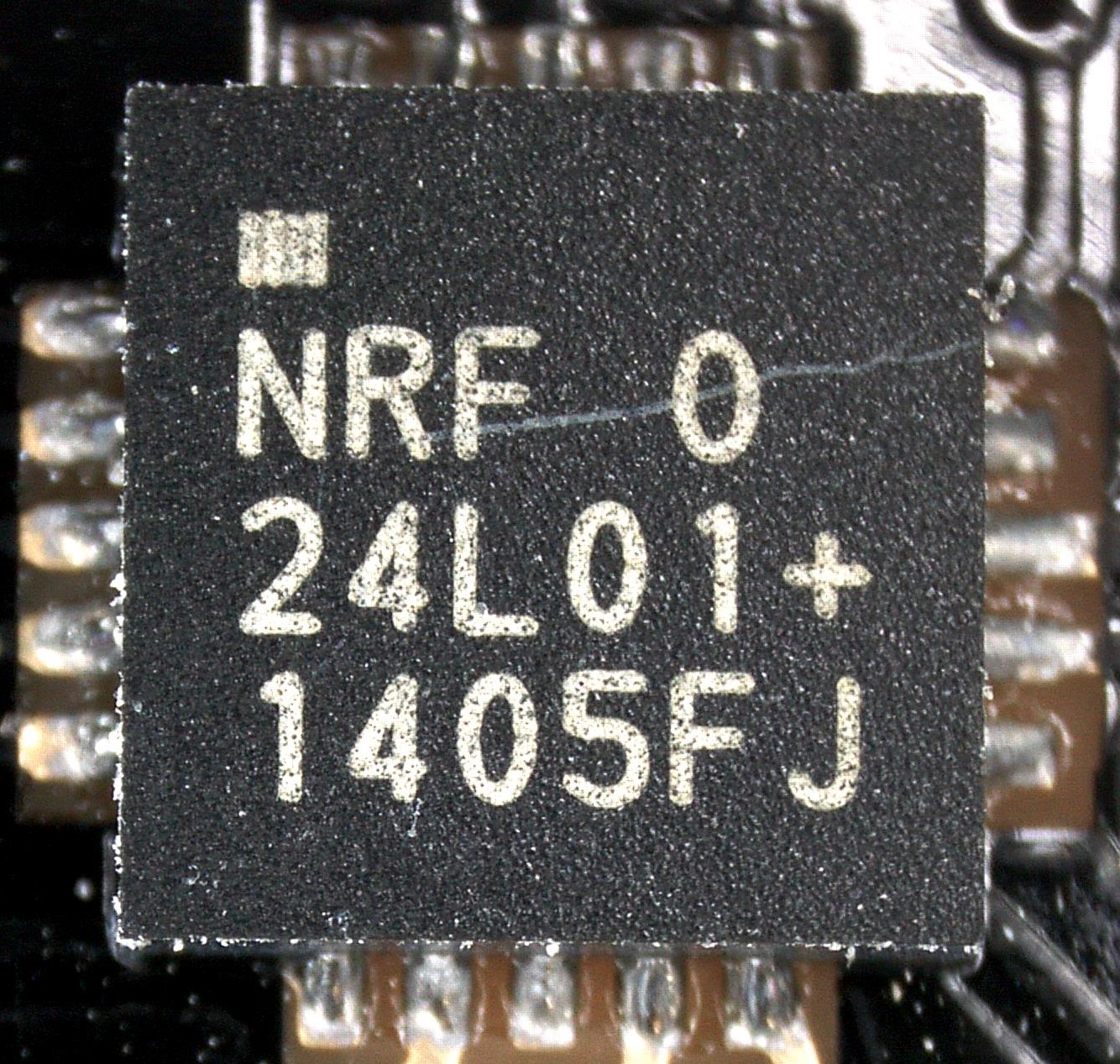
Anyone know by what method Nordic prints the lettering on the chips? In looking at Yveaux's CSI-like photos, from chip-to-chip all of the letters have some amount of black mixed in, but on some they seem to be gaps left by air bubbles (so you're seeing through paint gaps to the black background) from the lettering being sprayed on, and on others the black seems like black dust or or something that was sprinkled on top after the lettering was applied. So, if you look closely through a microscope, some differences do seem to emerge. Under magnification, the lettering on the 1331AF is visibly sloppy, almost as if printed by a professional cake decorator from your local bakery.
Anyone know what some of the other lettering is supposed to mean? e.g. M, AF, EV, CH, A, 0, CL, AE, DQ, FJ, or FY? On Hek's genuine chip, it seems blank after the NRF, whereas that's not true for any of the other chips.
-
My "regular" modules were bought from gc_supermarket and the NRF chips all have the following printing. There is no circle in the center of the +.
.
NRF  T
24L01+
1420JB
My LNA/PA modules were bought from alice11011983 and the NRF chips have the following printing. There is a circle in the center of the + on the first set, but not the second set.
.
NRF  M
24L01+
1431FC
. NRF O 24L01+ 1417GPI'll try to grab some pics this weekend.
Cheers
Al -
Update: I provided Itead with my contact information, and they will try to arrange for a Nordic FAE to contact me.
As there's no telling how long the above might take to resolve, I decided to roll the dice again and ordered three of these modules:
I hope to receive them by later in the week. I'm hopeful, but only slightly optimistic. If there's interest, I'll post closeups after I receive and test them.I also ordered more blob modules, but from a different source than the two I already have, so who knows what I'll actually receive. If it turns out blob modules from different sources are all about the same, I might standardize on that and simply move on. The two that I have work well enough that I wouldn't mind doing that, though it may put me on a fork from the rest of you. My only reluctance is that we'd all be more productive if we can find some way to leverage a common platform, so that remains my preference (and hope) for the long-term.
-
Anyone know by what method Nordic prints the lettering on the chips? In looking at Yveaux's CSI-like photos, from chip-to-chip all of the letters have some amount of black mixed in, but on some they seem to be gaps left by air bubbles (so you're seeing through paint gaps to the black background) from the lettering being sprayed on, and on others the black seems like black dust or or something that was sprinkled on top after the lettering was applied. So, if you look closely through a microscope, some differences do seem to emerge. Under magnification, the lettering on the 1331AF is visibly sloppy, almost as if printed by a professional cake decorator from your local bakery.
Anyone know what some of the other lettering is supposed to mean? e.g. M, AF, EV, CH, A, 0, CL, AE, DQ, FJ, or FY? On Hek's genuine chip, it seems blank after the NRF, whereas that's not true for any of the other chips.
@NeverDie said:
Did you use the microscope for the module shots also, or just the NRF chip
Only the chips were shot using my microscope. The field of view is simply too small to shoot the whole module.
Only > Since you have a nice module collection that spans different NRF chips and also different module types, have you noticed whether any of your modules stand out head-and-shoulders above the others as having clearly better performance?
No, but I had troubles mixing different modules in the past (even the NO_ACKs were involved iirr), so I'm very interested to know which ones are genuine.
-
@NeverDie said:
Did you use the microscope for the module shots also, or just the NRF chip
Only the chips were shot using my microscope. The field of view is simply too small to shoot the whole module.
Only > Since you have a nice module collection that spans different NRF chips and also different module types, have you noticed whether any of your modules stand out head-and-shoulders above the others as having clearly better performance?
No, but I had troubles mixing different modules in the past (even the NO_ACKs were involved iirr), so I'm very interested to know which ones are genuine.
@NeverDie said:
Anyone know by what method Nordic prints the lettering on the chips?
Yes, it's in the data sheet. The date code is in YYWWLL which stands for year & week of production, an LL indicates wafer lot. The top right code indicates the production location (first letter) followed by optional letter indicating engineering sample.
Nordic is fabless so only they know what the location letters mean.
The text is normally written using a laser scriber, so no ink is involved.
Thinking of it, differences in font/thickness etc. can be caused by different laser scribers at different production facilities (or even within one facility) so I'm starting to doubt if it will help us in distinguishing fakes from genuine. -
@NeverDie said:
Anyone know by what method Nordic prints the lettering on the chips?
Yes, it's in the data sheet. The date code is in YYWWLL which stands for year & week of production, an LL indicates wafer lot. The top right code indicates the production location (first letter) followed by optional letter indicating engineering sample.
Nordic is fabless so only they know what the location letters mean.
The text is normally written using a laser scriber, so no ink is involved.
Thinking of it, differences in font/thickness etc. can be caused by different laser scribers at different production facilities (or even within one facility) so I'm starting to doubt if it will help us in distinguishing fakes from genuine.@Yveaux said:
@NeverDie said:
Anyone know by what method Nordic prints the lettering on the chips?
Yes, it's in the data sheet. The date code is in YYWWLL which stands for year & week of production, an LL indicates wafer lot. The top right code indicates the production location (first letter) followed by optional letter indicating engineering sample.
Nordic is fabless so only they know what the location letters mean.
The text is normally written using a laser scriber, so no ink is involved.
Thinking of it, differences in font/thickness etc. can be caused by different laser scribers at different production facilities (or even within one facility) so I'm starting to doubt if it will help us in distinguishing fakes from genuine.Thanks for pointing that out. Looking at the version 1.0 spec sheet (available at http://www.nordicsemi.com/eng/Products/2.4GHz-RF/nRF24L01P), I see it covered in section 13.1 and 13.2.
Curiously, according to the spec sheet, the chips should be marked "nRF", not "NRF".
-
@Yveaux said:
@NeverDie said:
Anyone know by what method Nordic prints the lettering on the chips?
Yes, it's in the data sheet. The date code is in YYWWLL which stands for year & week of production, an LL indicates wafer lot. The top right code indicates the production location (first letter) followed by optional letter indicating engineering sample.
Nordic is fabless so only they know what the location letters mean.
The text is normally written using a laser scriber, so no ink is involved.
Thinking of it, differences in font/thickness etc. can be caused by different laser scribers at different production facilities (or even within one facility) so I'm starting to doubt if it will help us in distinguishing fakes from genuine.Thanks for pointing that out. Looking at the version 1.0 spec sheet (available at http://www.nordicsemi.com/eng/Products/2.4GHz-RF/nRF24L01P), I see it covered in section 13.1 and 13.2.
Curiously, according to the spec sheet, the chips should be marked "nRF", not "NRF".
-
My "regular" modules were bought from gc_supermarket and the NRF chips all have the following printing. There is no circle in the center of the +.
.
NRF  T
24L01+
1420JB
My LNA/PA modules were bought from alice11011983 and the NRF chips have the following printing. There is a circle in the center of the + on the first set, but not the second set.
.
NRF  M
24L01+
1431FC
. NRF O 24L01+ 1417GPI'll try to grab some pics this weekend.
Cheers
Al@Sparkman said:
My "regular" modules were bought from gc_supermarket and the NRF chips all have the following printing. There is no circle in the center of the +.
.
NRF  T
24L01+
1420JB
My LNA/PA modules were bought from alice11011983 and the NRF chips have the following printing. There is a circle in the center of the + on the first set, but not the second set.
.
NRF  M
24L01+
1431FC
. NRF O 24L01+ 1417GPI'll try to grab some pics this weekend.
Cheers
AlHi Al,
Funny that you happen to mention gc_supermarket, because just yesterday I was noticing that they had good pricing on blob modules. These visually resemble the two blob modules I have and which seem to perform quite well at 1mbps air datarate. Intriguingly, the listing title says "Power enhanced version Compatible NRF24L01" and in the description it says:
"This module is design to solve the problem of small power in NRF24L01 module, its distance is far away than NRF24L01
Please download the data in below link
http://www.ai-thinker.com/forum.php?mod=viewthread&tid=411&extra=page%3D1 "It would be easy to dismiss this as gibberish or as a failed attempt at chinglish, except for the fact that my two blob modules do, in fact, seem to have much better range than any of the "regular" NRF24L01+ modules I've tried so far. So, whether deserved or not, that does seem to give gc_supermarket more credability in my eyes than a lot of other re-sellers. Also, whether by luck or intent, they referred to it as "NRF24L01", not "NRF24L01+", which is also closer to reality, as it doesn't support 250kbps. So, in my book they get some credibility points for that also.
Have your transactions to date with gc_supermarket gone well?
Hello! It looks like you're interested in this conversation, but you don't have an account yet.
Getting fed up of having to scroll through the same posts each visit? When you register for an account, you'll always come back to exactly where you were before, and choose to be notified of new replies (either via email, or push notification). You'll also be able to save bookmarks and upvote posts to show your appreciation to other community members.
With your input, this post could be even better 💗
Register Login