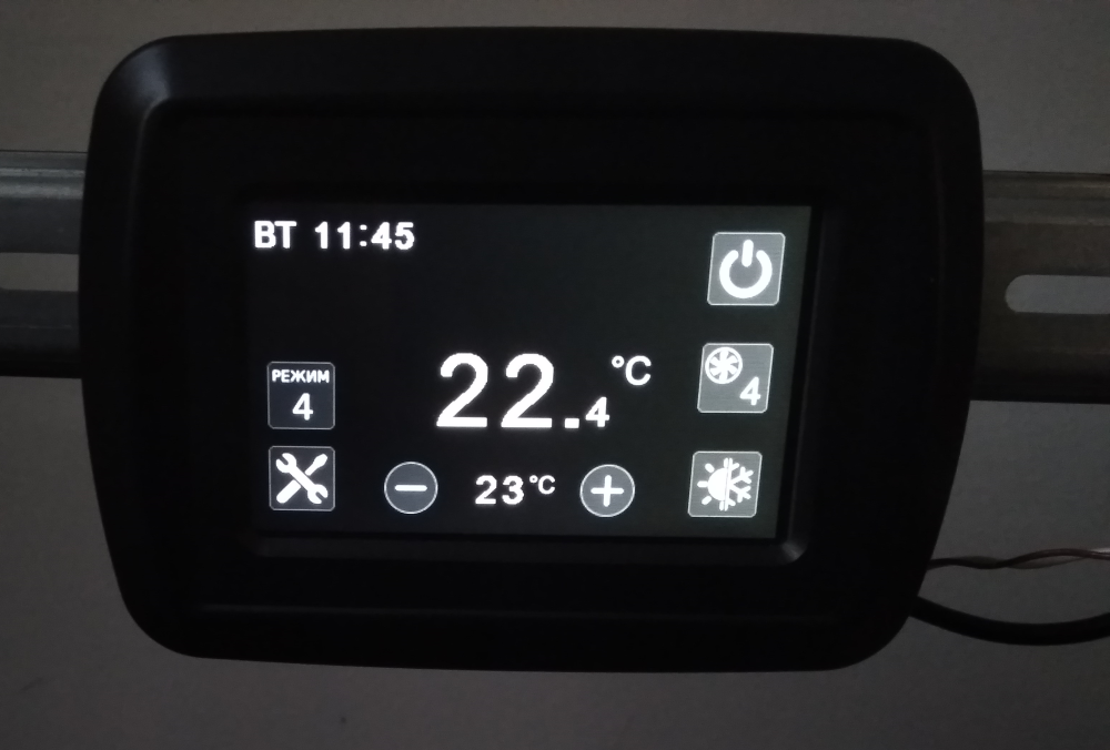
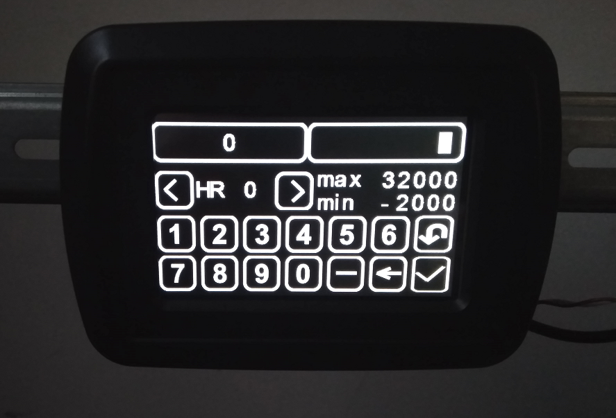
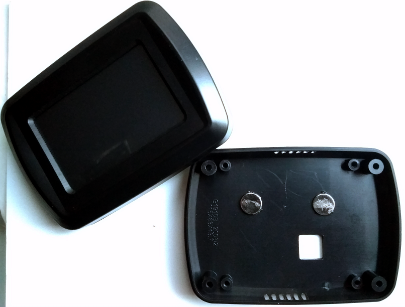
@NeverDie EMI is a big topic. I think there will be no problems. I am going to do some tests of communication
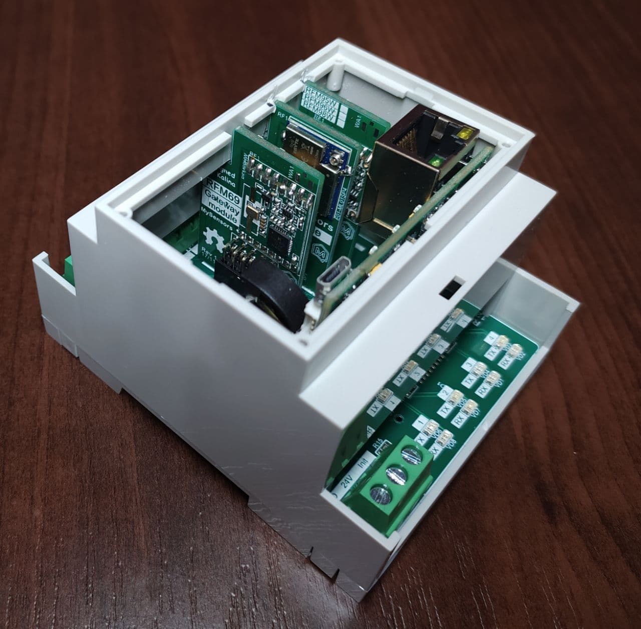
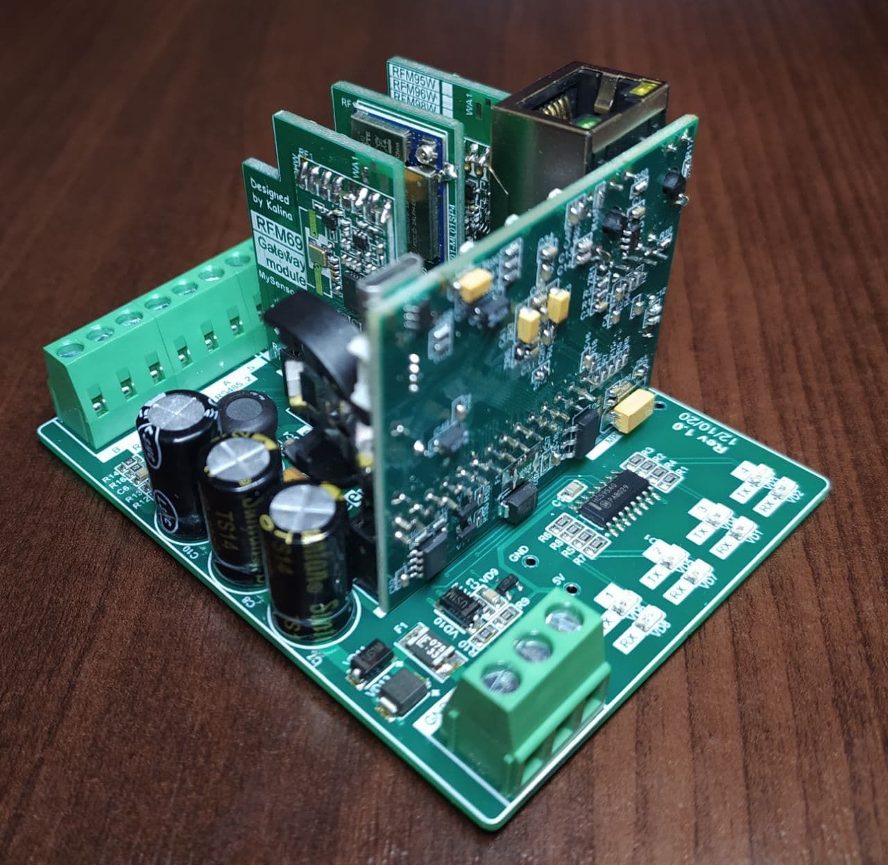
quality for various modules and antennas. As for the antennas, I am going to fixed them to the body through the holes, but I have not yet decided on the location. As for connection antenna to the module you can see the on photo ...
Posts made by kalina
-
RE: What did you build today (Pictures) ?
-
RE: What did you build today (Pictures) ?
@monte Not certainly in that way. In this project, everything is open source with the exception of the board with an ethernet (based on STM32). The ethernet board was developed by my partners and they are not ready to share it yet. But I hope I can persuade them to do it
-
RE: What did you build today (Pictures) ?
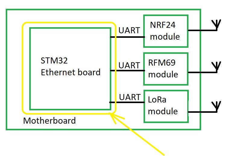
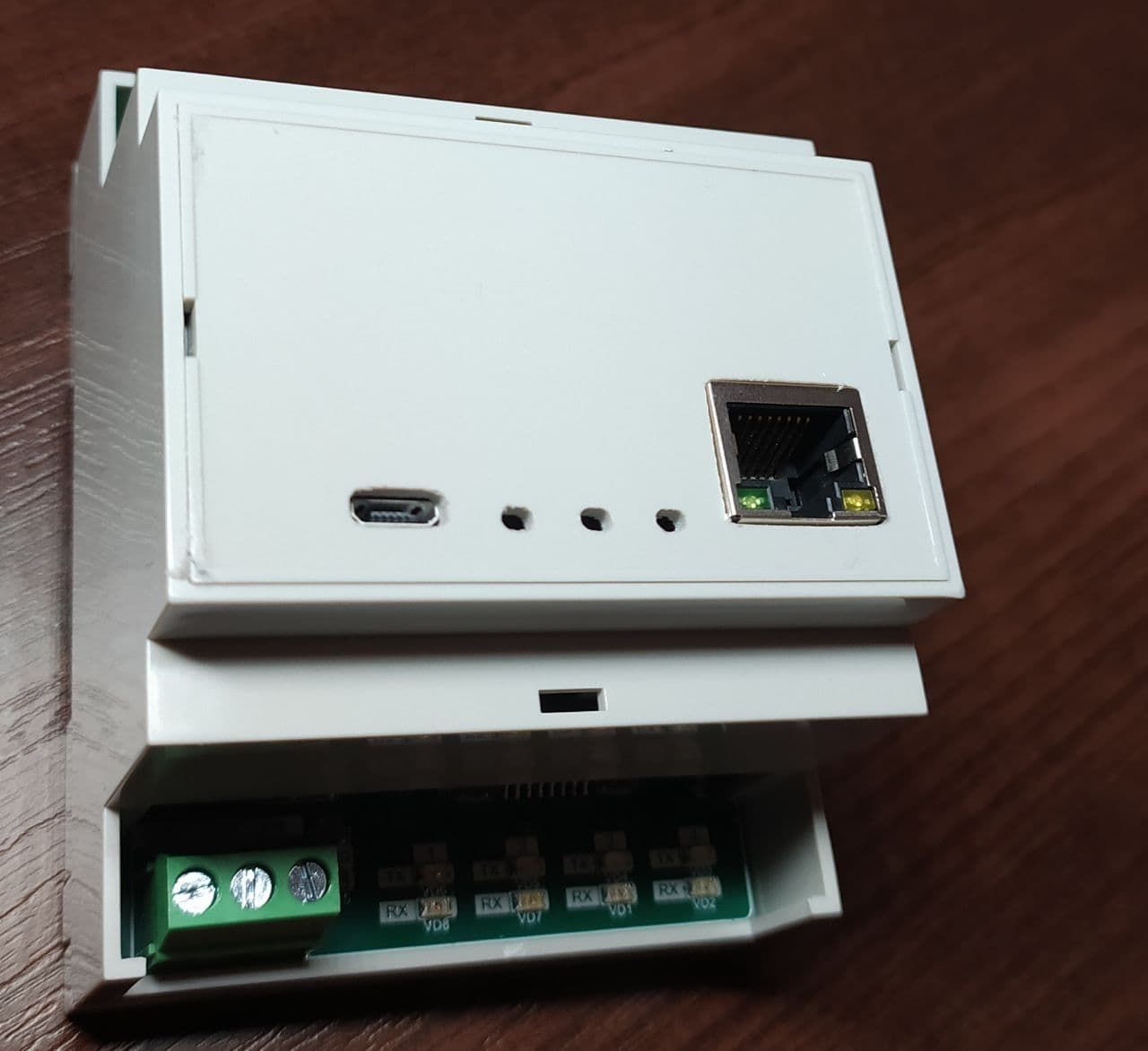
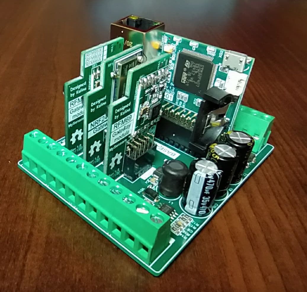
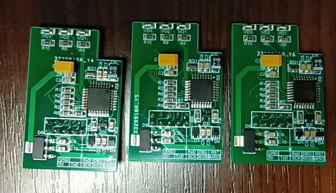
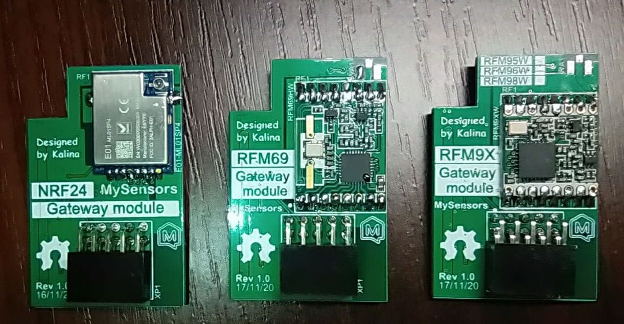
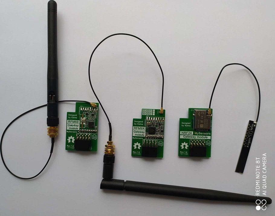
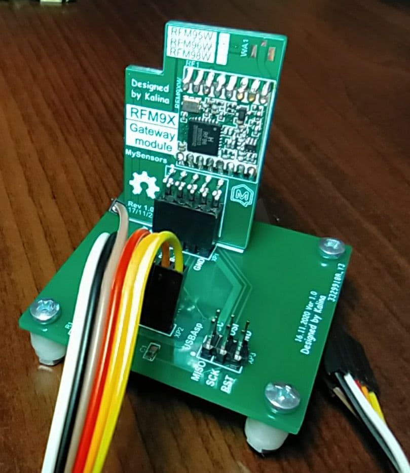
Oh yes, I forgot to share photos of my new project - Multinetwork Mysensors Gateway. The main idea of this gateway is that it can at the same time serve up to four different networks (Lora - RFM9X, 2.4 GHz - NRF24 and ISM band RFM69). These networks can be assembled in separate modules and each user can build own set of modules. The incoming stream will be connected via Ethernet on various ports, for example, the gate will have the IP address 192.168.1.128, and each subnet will be served on ports 5003 - the first subnet, 5004 - the second, and so on ...
-
RE: What did you build today (Pictures) ?
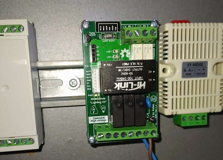
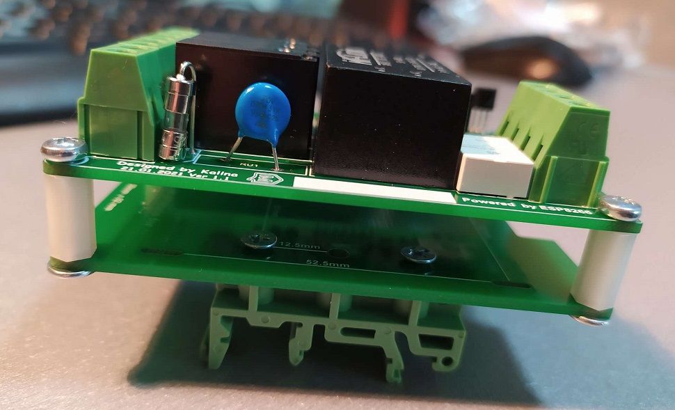
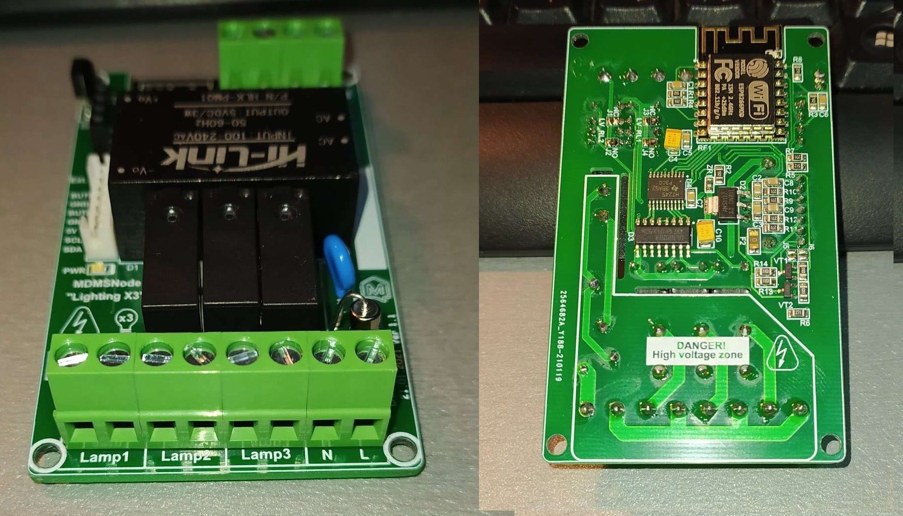
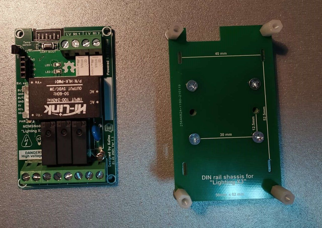
Today i have assembled the latest revision of my Lighting X3 for DIN rail mounting.
-
RE: ๐ฌ MDMSNode "Lighting X3" (based on ESP8266)
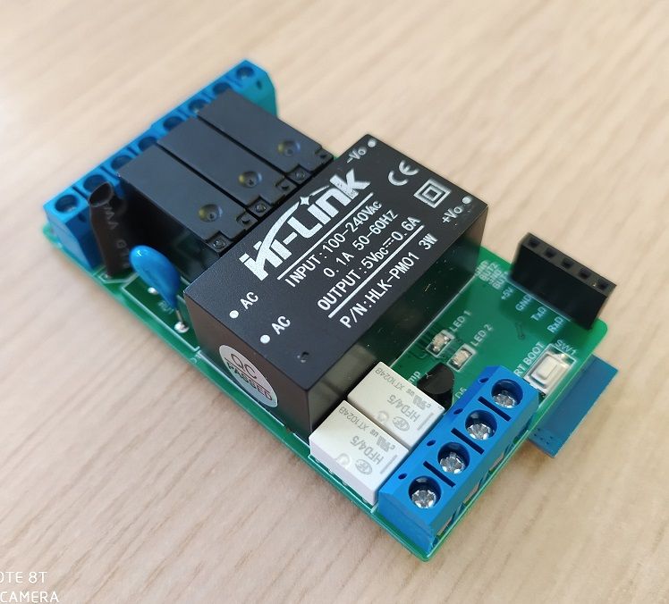
The device is soldered and fully tested!
-
RE: What did you build today (Pictures) ?
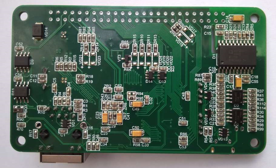
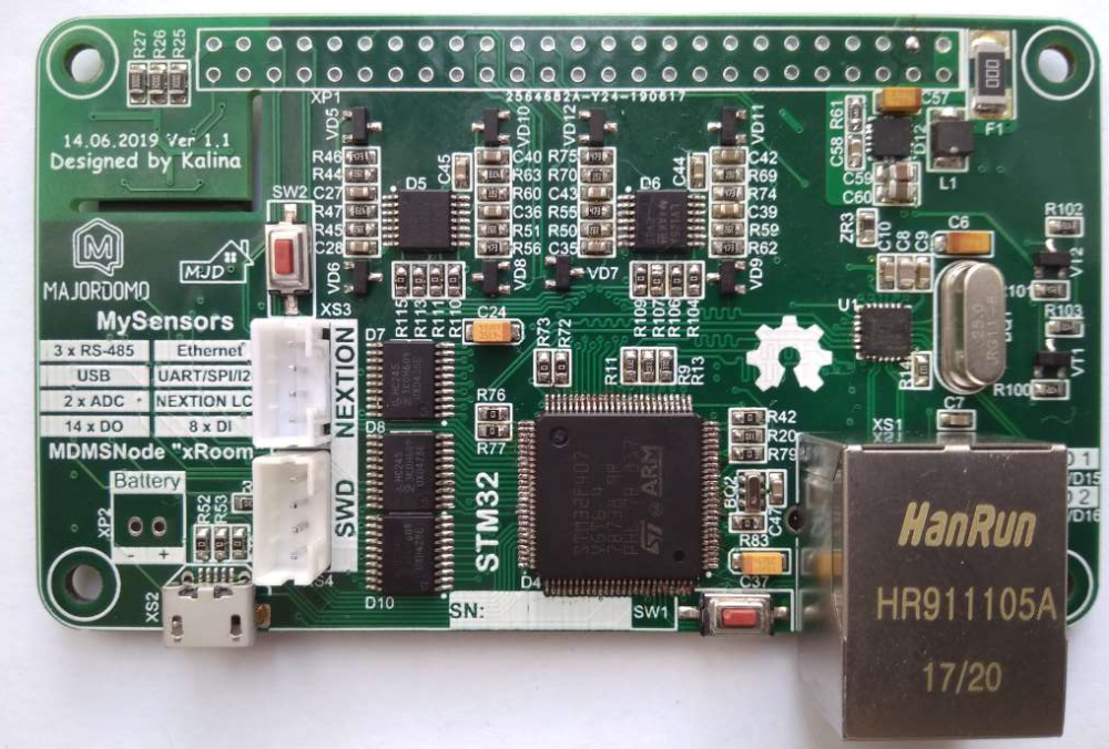
I have soldered the first sample of "xRoom" board.
TODO: testing and detail description of the project)) -
RE: ๐ฌ MDMSGate
Hi @berkseo. Thanks for the suggestion, but could you describe in more detail? As for my TODO list, there is already a task to add 485 interface to the gateway. My latest device "xRoom" have this interface.
ps/ Where have you gone?
I have been working on "xRoom" shield. A small announce:
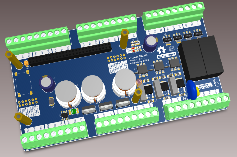
Do you remember the discussion about multinode? So, it will be available soon))
-
RE: ๐ฌ MDMSGate
I am going to production a new batch of gateways, but before that I want to upgrade it. Does anyone have any suggestions for improving current version MDMSGate?
-
RE: ๐ฌ MDMSNode "Lighting X2"
Hi @blackchart,
Unfortunately, all devices are sold out. Further production is possible only when ordering more than 10 devices (in this case, I also can modify the device to suit your needs). -
RE: ๐ฌ MDMSNode "Lighting"
Hi @aramko-aramko.
Unfortunately, this model is already sold. You can look at the upgraded version of this device - MDMSNode "Lighting" Rev 1.1. -
RE: ๐ฌ MDMSGate
Hi @animal64, we are glad to welcome you in the MySensors community.
I don't use MQTT, but one of users, who took the gateway, did some work in this direction, you can find on this link - https://gitlab.com/denissp/mdmsgate_mqtt/
Yes, for each type of radio module you need your own gateway, its own subnet. This means that two gateways are needed.
If you have any questions, please contact us, we will always be happy to help
-
RE: ๐ฌ MDMSPanel "Nextion"
@sebdetours said in MDMSPanel "Nextion":
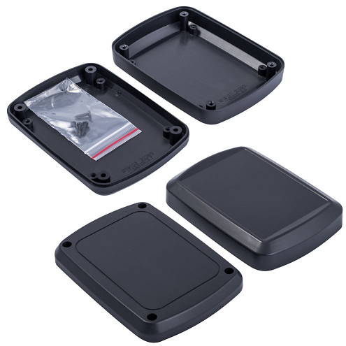
Did you take a standart case that you cut out?
Hi @sebdetours, yes. This is G1910 (Gainta) box. See drawing attached to projet files.
-
RE: What did you build today (Pictures) ?
@bjacobse said in What did you build today (Pictures) ?:
Yes it's very impressing what you have achieved
Thanks, the project is published already.
-
RE: What did you build today (Pictures) ?
@dbemowsk Yes, it is a factory case, and before the changing it looked like this :
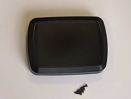
At the moment this is termostat, but I will not limit myself to this)) The purpose of the panel will be determined by the software project loaded into it. I will describe this in more detail when I publish the project.
-
RE: What did you build today (Pictures) ?
@alowhum Yes of course. I am going to publish this project this week.
-
RE: What did you build today (Pictures) ?
I have finished an enclosure for the my MDMSPanel "Nextion" today.
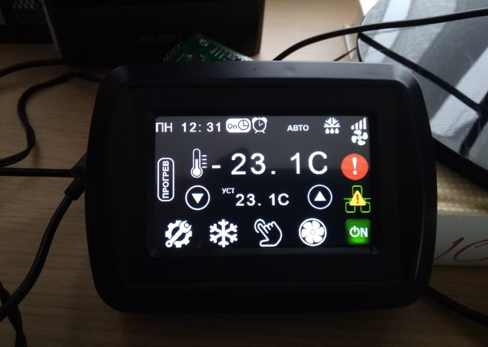
-
RE: Is kickstarter feature need for the openhardware?
Hi @hek, I understand what is the problem now. Really, just desire is not enough))
-
Is kickstarter feature need for the openhardware?
Nothing to explain. Openhardware.io is amazing site. If this feature is added, it will take the site to a new level.
What do you think about this?
P.S. If you agree, you can vote my post.
-
RE: What did you build today (Pictures) ?
@alexsh1 Yes, it will be a scene controller. I also developed nice enclosure with a magnetic mount. In a few days I will share new photos.
-
RE: What did you build today (Pictures) ?
@mfalkvidd I would to say what this board is the most necessary for me at the moment. I tired of using various gadgets as a control panels for my nodes. Also, i want to try RS-485 in conjunction with MySensors. Next step is add RS-485 to my MDMSGate....
-
RE: What did you build today (Pictures) ?
Some photos of my new device - MDMSPanel "Nextion". I have finished soldering an hour ago)) Next week i will public this project.
-
RE: ๐ฌ MDMSNode "Lighting" Rev 1.1
@jeremushka I developed this device and added functionality to it that can be useful for many users of MySensors technology. Personally, I use only the lamp on / off function. I do not use the wall switch, current flow detecting, etc. I can only theoretically answer on your questions. For confirmation it, is necessary to implement all this in the sketch.
@jeremushka said in MDMSNode "Lighting" Rev 1.1:
Do you detect in the firmware if the light is off or on with the ACS712 ?
It is possibility.
@jeremushka said in MDMSNode "Lighting" Rev 1.1:
Does the push switch from the wall will still be acting independently of this Mysensors board?
Wall switch must connect directly to terminal block. No other connections should be.
@jeremushka said in MDMSNode "Lighting" Rev 1.1:
Light status (on/off) will update when the physical switch will be pressed?
This needs to be controlled by the sketch.
-
RE: ๐ฌ MDMSNode "Lighting"
@jeremushka Please look at the description MDMSNode "Lighting" Rev 1.1, everything is indicated there...
-
RE: ๐ฌ MDMSNode "Lighting"
@jeremushka This project has some shortcomings. For this reason I have released a new, more advanced version - MDMSNode "Lighting" Rev 1.1. If you are interested, I have more than 10 pcs in stock.
-
RE: What did you build today (Pictures) ?
@tsjoender said in What did you build today (Pictures) ?:
Looks neat! How did you do the cutout of the sides of these enclosures?
No magic, this is the work of the CNC...)))
-
RE: What did you build today (Pictures) ?
@nagelc
OK, I will keep you informed of developments on this project ... -
RE: What did you build today (Pictures) ?
I have assembled a few UPS ... now I am testing these hardware.
-
RE: What did you build today (Pictures) ?
LED backlight for my CNC machine....
-
RE: ๐ฌ Single board computer UPS
First soldered device:
And a small test:
-
RE: ๐ฌ Single board computer UPS
@berkseo Hello,
Thanks!
First of all I have to check hardware part, and then i am going to develop software. In my opinion, production will be start in a month. I'll share photos of the soldered device tomorrow. -
RE: ๐ฌ Single board computer UPS
The second revision of "Raspberry UPS" which now called "Single borad computer UPS" was received yesterday from PCBWAY.com
-
RE: ๐ฌ Single board computer UPS
I tested this device yesterday and found some issues. Now, I want to share results.
-
The analog comparator circuit must be modified. AIN0 should left floating (unconnected) and to this pin need connect the internal 1.1V bandgap reference. The 5V_Fail signal must be connected to AIN1 pin.
-
VD7 must be removed and DC-DC will be works all time except power save mode.
-
Need to add the MOSFET for manage LiPo charger, because this IC interrupts accumulator detecting signal (this signal always near 4..5 volts).
-
Need to add the 5V (external) detecting signal to the microcontroller .
-
Many of the components values should be revised.
All these remarks will be taken into account in the new revision.
Everything else works perfectly!
For the first revision of the device, I'm completely satisfied with the result. -
-
RE: ๐ฌ MDMSGate
The new batch of the MDMSGate (without an enclosure and cheaper) is already available....
-
RE: ๐ฌ Single board computer UPS
@giltesa I order boards assembly in Ukraine. This is a small company that develops and small-scale production of electronics. The price is very different and depends on many factors, such as quantity and size of components, number of devices, etc. All questions are discussed individually.
-
RE: ๐ฌ Single board computer UPS
@gohan Yes. This first board was soldered manually. But I use the services of soldering in general.
-
RE: ๐ฌ Single board computer UPS
@alexsh1
You share really great UPS! But in my case I need UPS for outdoor usage. I am going to use this UPS on temperature -20 C and lower. As for multiple settings, I put Atmega328p inside, so this UPS will be Arduino compatible and will have multiple settings too. -
RE: ๐ฌ Single board computer UPS
I have received pcb from PCBWAY today. 11 pcs were in the box instead 10
As always, quality is excellent for little money! In a few days I'll assembly the boards.
-
RE: ๐ฌ Single board computer UPS
Hello @giltesa
I have been looking for an enclosure for this device long time. But i didn't find suitable DIN rail enclosure. At first looks like that this one is suitable, but later one of the sizes does not fit. -
RE: ๐ฌ MDMSGate
My intention was to change the channel of the NRF24L01, the transfer speed, and configure the ATSHA204A.
You can make any changes that the MySensors library allows.
do you plan to release a second version?
I am completely satisfied with this version. But despite this,
i think about a new version all the time: RS485, Bluetooth, MQTT ... what else???, So, i still don't see "the main feature" of the second version. As soon as i will find it, second version will be released immediately.Why is the sketch configured with MY_RF24_PA_LEVEL = RF24_PA_LOW?
Because RF24_PA_LOW configuration completely covers an area on which all my nodes are located. And I see no reason to increase the power.
-
RE: ๐ฌ MDMSGate
Your gateway worked all day like a champion!
Nice to hear! MDMSGate is my first and the best device))
Is this code? https://github.com/DmytroKalinkin/MDMS/blob/master/Gateway_2.4GHz/Gateway_2.4GHz.ino
Yes, MDMSGate is programmed by standard serial gateway sketch.
Do you only need that to work for NRF24L01+Ethernet?
No, I also use (in some case) serial and Wi-Fi connection. For the serial connection just change jumpers position. As for Wi-Fi connection you can read this
https://www.openhardware.io/dl/5782866b09fcb093053825e4/design/MDMSGate. Manual for installing Wi-Fi.pdfThe sketch the same in all modes.
-
RE: ๐ฌ Single board computer UPS
Today I have received a holder for DIN rail and i am trying to apply it for my enclosure now.
-
RE: ๐ฌ Single board computer UPS
@mfalkvidd said in Raspberry UPS (external):
@kalina does it support connecting both batteries at the same time, giving the lipo priority since it is rechargeable? or does the user choose to connect only one of the batteries?
Yes, both batteries can be connected at the same time. This is allowed by circuit design - separate channels with MOSFET (see pic below).
One of the tasks is develop the algorithm of functioning (priority and so on ..) -
RE: ๐ฌ Single board computer UPS
@gohan said in Raspberry UPS (external):
Why the 2 batteries?
Because each battery has own advantages and disadvantages. I see the next picture:
I think that UPS must support both battery types.
-
RE: What did you build today (Pictures) ?
@sindrome73 said in What did you build today (Pictures) ?:
@kalina
And then once connected to the Raspy ?? What are you doing?? And a new thing for me !!Maybe this picture will explain my intentions
-
RE: What did you build today (Pictures) ?
@sindrome73 said in What did you build today (Pictures) ?:
The audio socket what is it for ???
For connecting the audio system to the RPI3
-
RE: What did you build today (Pictures) ?
Today I have finished work on control center for my smart home. The box includes a Raspberry Pi 3, gateway, ethernet switch, power supplies 5V and 9V. Audio input jack, ethernet and AC line cabels out from the box. Maybe, a GSM module should be included to the free space too (i will thinking about...). I am going to install this box in the near future.
-
RE: ๐ฌ Optical Inclinometer
@hek Thanks for the clarification. All this time I have been thought that this resource is open hardware area for projects related to the MySensors technology.
-
RE: ๐ฌ Optical Inclinometer
@stevem How does this refer to MySensors technology?
-
RE: ๐ฌ Wireless Touch Switch: Relay Model - (For Livolo crystals)
@giltesa What fuses values were setted? As i understood, you are using DualOptiboot.
-
RE: ๐ฌ MDMSGate
One question: will I be able to use Wifi, Serial OR (not and) LAN if I follow the steps from your instruction? As in just change jumper positions and use the other one? Does the sketch support that?
Yes, you're absolutely right. It was the main goal. The mode changing just with change jumpers position. And as for sketch - in all 3 modes it is standard serial gateway sketch. I have written about it befor ....
-
RE: ๐ฌ Wall Socket Insertable Node
@yury I have a little experience with AD7148 and 7150 chips in one of my projects . You are right, there wasn't a high voltage traces.
-
RE: ๐ฌ MDMSGate
@marvin78 Hi, as i understand you got MDMSGate without Wi-Fi (ESP-12), because you didn't specify it in the order. I have written a small manual that describes how to start work in Wi-Fi mode in this case. Please, go to "Design files" menu and download "MDMSGate. Manual for installing Wi-Fi.pdf" file.
-
RE: ๐ฌ Wall Socket Insertable Node
@yury What do you think about capacitive button "On/Off" to the right corner from led? Look at the pic below...
-
RE: ๐ฌ Wall Socket Insertable Node
@jeremushka In my opinion you should have two modes - automatic (with mysensors) and manualy (without). In manualy case the wall plug must be always under the voltage and you don't need detect plug a device. But how are you going to switch mode - this is a question...
-
RE: ๐ฌ MDMSNode "Lighting" Rev 1.1
The first batch of devices will be shipping to the customer soon
-
RE: ๐ฌ MDMSNode "Power"
@sindrome73 OK, but it could be in 1-2 weeks, as i wrote earlier, i very busy now...
-
RE: ๐ฌ MDMSNode "Power"
@sindrome73 Of course, yes. It's a matter of time. I have a lot of tasks at work and I can't do this right now.
-
RE: ๐ฌ MDMSNode "Power"
@lagrosso69
OK, the MDMSNode "Power" is selling with a programmed bootloader and a sketch inside. -
RE: ๐ฌ DIP to SMD NRF24L01 adapter
Hi @reinhold.
@reinhold said in DIP to SMD NRF24L01 adapter:
Also: Any reason you are "wasting" a lot of space on the board? I suppose you wanted to make the adapter the same width as the DIP nrf24l01+?
Yes, In this case, the size didn't matter
@reinhold said in DIP to SMD NRF24L01 adapter:
It seems @kalina is using the 10nF, 1ยตF + 10ยตF combo in his designs, so it's not neccessary for him to add them to the adapter.
You are absolutely right. In my projects there are all the necessary components for achieving good power. And in this adapter I only traced polygon pours for 3.3V, because in my opinion the radio module should not be powered by narrow conductors.
@reinhold said in DIP to SMD NRF24L01 adapter:
it would be nice to have the pads on the adapter in case one wants to add the capacitors directly with the wireless module
OK. I will take this into account for the following developments.
I found one significant drawback of this adapter - it is shorter in length compared to the original radio module (DIP). So if it (adapter+SMD NRF) is soldered into a board, then the antenna will be located directly above the copper layer. Communication in this case will be bad. So, I had to solder the connector between the adapter and the SMD radio module, so that the antenna of the radio has moved beyond the board's dimensions. Please, look at picture below, it will explains better...
-
RE: ๐ฌ MDMSGate
I have uploaded a small instruction "MDMSGate. Connection to Domoticz". This instruction explains how connect MDMSGate to Domoticz via LAN.
-
RE: ๐ฌ MDMSNode "Power"
@lagrosso69 said in MDMSNode "Power":
hello have you a sample program to try MDMSNode power
Hi @lagrosso69. Do you mean a sketch? Did you order pcb and solder MDMSNode "Power" by yourself?
-
RE: ๐ฌ MDMSNode "Power"
@JWB said in MDMSNode "Power":
What CAD program are you using for this project? The board file does not seem to be Eagle or KiCad.
I use Altium Designer.
-
RE: ๐ฌ DIP to SMD NRF24L01 adapter
@NeverDie said in DIP to SMD NRF24L01 adapter:
if you could center the 8 pin connector, it would be better from my point of view.
OK. I'll do it in my next revision of this adapter.
-
RE: ๐ฌ DIP to SMD NRF24L01 adapter
@NeverDie said in DIP to SMD NRF24L01 adapter:
There seems to be a fault in those drilling instructions though.
Yes, I see. The problem is that I released the gerber files in the metric system. Now I have released a new drill file. You can try again.
-
RE: ๐ฌ MDMSGate
My plan is to use MQTT and Wi-Fi mode. Is this possible?
Unfortunately, no. This gateway uses a microcontroller PIC18F67J60. Firmware of this uC doesnt support MQTT protocol (in future I probably add this feature). You can only use it as a ethernet gateway. In Wi-Fi mode, the ESP-12 module acts as well as the PIC18F67J60 microcontroller - converts the packets of TCP/IP to UART and vice versa.
Connection to controller through Ethernet :
- Connect MDMSGate to the router (network). After this router will define IP address for gateway through DHCP (for example 192.168.1.6). You also can see this adress in router web interface.
- Open web interface of the controller and fill "IP address" and "Port" for the Ethernet gateway.
- Click "Connect" button and work!
Connecting through Wi-Fi a bit more complicated. If you want I can explain.
-
RE: ๐ฌ MDMSNode "Lighting" Rev 1.1
@artipi At the first I should check the new design (ordering pcbs + wait delivering (3 weeks) + solder and test (3-4 days). In my opinion, it will be in September.
-
RE: NRF24L01 SMD to DIP converter
@bilbolodz said in NRF24L01 SMD to DIP converter:
What's the size of these PCB?
If you need get size for ordering - you can specify 15.2x15.5mm.
-
RE: NRF24L01 SMD to DIP converter
@bilbolodz said in NRF24L01 SMD to DIP converter:
At the begging quick question: are you sure that all is fine with drills?
Yes.
@bilbolodz said in NRF24L01 SMD to DIP converter:
I've always took "the cheapest product and shipment option
For example, 20 pcs with delivery (to Poland) cost 11$ on PCBWay.
-
RE: NRF24L01 SMD to DIP converter
@bilbolodz said in NRF24L01 SMD to DIP converter:
if you provide gerber files for PCB factory
Already added to project files.
-
RE: NRF24L01 SMD to DIP converter
@bilbolodz said in NRF24L01 SMD to DIP converter:
Any ideas?
Yes, I have one - https://www.openhardware.io/view/449/DIP-to-SMD-NRF24L01-adapter
-
RE: ๐ฌ MDMSNode "Lighting X2"
Some news about project stages - I have received PCBs already and going to soldering devices...
-
RE: ๐ฌ MDMSGate
Unfortunately, for a while the MDMSGate will not be available for the sale (all 15 gateways have been sold). Now I am going to start the next 30 pcs into production. If someone wants to pre-order, please, send a PM to me.
-
RE: ๐ฌ MDMSGate
@Anticimex , I have already uploaded the necessary license files.
-
RE: How can I manage S_LIGHT_BINARY child in Domotics?
It works!!! I just have pressed on lamp picture
and my lamp (in the room) switched on
@mfalkvidd, thanks again. -
RE: How can I manage S_LIGHT_BINARY child in Domotics?
For example, i know how manage it in MYSController...
-
RE: How can I manage S_LIGHT_BINARY child in Domotics?
@mfalkvidd said in How can I manage S_LIGHT_BINARY child in Domotics?:
@kalina go to Setup->Devices and click the green arrow ("Add device"). It should then show up on the "Switches" tab.
I have done as you said and...
and then I click on Edit button
But I still don't know how bind this switch with S_LIGHT_BINARY of my node? -
How can I manage S_LIGHT_BINARY child in Domotics?
Hi,
I have conected gateway to controler via Ethernet.
And I see my node with children.
Question - how i can change (turn on/off) S_LIGHT_BINARY state? What i have to do?
Can anybody help me? -
RE: ๐ฌ MDMSNode "Power"
@sundberg84, vias connect the AC traces on the TOP and BOT layers (see picture). This was done for reduce resistance of the conductors and distribute the heat caused by the flow of large currents through them.
-
RE: ๐ฌ MDMSNode "Power"
Luckily, the device has started up without problems. Yesterday I tested it, even the kettle worked through the device (9A). Now I can share the source files of the project (already are refreshed).
-
RE: ๐ฌ MDMSNode "Power"
@Samuel235 said in MDMSNode "Power":
Hope to see the tests completed without issue for you
Thanks! But for the first release it sounds extremely optimistic :bowtie:
-
RE: ๐ฌ MDMSNode "Power"
I have received pcbs and i am waiting for components now for device testing.
PCBWAY.com sent me pcbs in less than 2 weeks, as always super quality, thanks to them!
-
RE: ๐ฌ MDMSensor "Multisensor"
@gohan Yes, you are right, this is done by cnc router.
-
RE: ๐ฌ MDMSensor "Multisensor"
I have made the firtst device with enclosure already...
-
RE: ๐ฌ MDMSAccessory "Programming"
First "Programming" have assembled and tested...
-
RE: ๐ฌ MDMSGate
@pointbre Hi, i am sending to you a PM. Check it pls in a few minutes...
-
RE: ๐ฌ MDMSNode "Power"
@Samuel235 Firstly I choose the type of device that I want to design, then I look for suitable enclosure. Further work involves the placement of everything in the enclosure. In addition to that, I always use 3D modeling for appreciating the ability to do the task.