Navigation

    • Register
    • Login
    • OpenHardware.io
    • Categories
    • Recent
    • Tags
    • Popular
    1. Home
    2. rmtucker
    3. Posts
    • Profile
    • Following
    • Followers
    • Topics
    • Posts
    • Best
    • Groups

    Posts made by rmtucker

    • RE: CNC PCB milling

      @neverdie
      Is it working correctly if you just issue a G0 x10 then x-10?
      did you switch to the jpadie workspace for v1.1?
      sounds like you have a short on pin 5

      posted in General Discussion
      rmtucker
      rmtucker
    • RE: Atmega 328p memory

      @mfalkvidd said in Atmega 328p memory:

      @dbemowsk I like this device because it has headers so no soldering strictly required. Note that the distance is smaller than the "standard" 2.4mm.

      https://www.aliexpress.com/item/NRF51822-2-4G-Wireless-Module-Wireless-Communication-Module-Bluetooth-module-zigbee-module-DMX512/32726191346.html

      The 2mm pitch is a pain if you do not use the BLE400 motherboard that goes with it.
      It took me ages to source a 2mm pitch protoboard then sockets to plug it into.
      But it is easy to use.โ˜บ

      posted in Hardware
      rmtucker
      rmtucker
    • RE: CNC PCB milling

      @neverdie
      What if you have broken .048 off the end of the tool during autolevel?
      So run some g-code above the job then re-probe so you know you have not twatted the tool.โ˜บ

      posted in General Discussion
      rmtucker
      rmtucker
    • RE: CNC PCB milling

      @neverdie
      Maybe run step 1
      Then run some g-code but above the job.(for a few mins).
      Then run step 3.
      This could be an autolevel problem.

      posted in General Discussion
      rmtucker
      rmtucker
    • RE: CNC PCB milling

      @neverdie
      Forget using probe to begin with as this would show lost steps but also any mechanical inaccuracy.
      Just concentrate on the motors to begin with.

      posted in General Discussion
      rmtucker
      rmtucker
    • RE: CNC PCB milling

      @neverdie
      Hmmm how long is a piece of string.๐Ÿ˜€
      My machine is on a much larger scale but the principal is the same.
      Is this a mechanical inaccuracy or lost steps?
      Make yourself a small program that rapids each axis in turn from one end of the axis to
      the other.
      On my own machine the motors are running pulleys to the leadscrews/ballscrews.
      I place a mark on the pulleys and a pointer (pin and blue tac) when the machine is at 0,0,0.
      I run the program and adjust the accel and velocity returning to 0,0,0 every time and checking the marks always line up.(If they don't lowering the settings 10% and running again).
      Which eventually proves it is not lost steps.

      posted in General Discussion
      rmtucker
      rmtucker
    • RE: CNC PCB milling

      Normally i would turn one up at a time until the motors lose steps,then pull them back 20%.

      posted in General Discussion
      rmtucker
      rmtucker
    • RE: CNC PCB milling

      @neverdie
      Yes or use bCNC to set them.

      posted in General Discussion
      rmtucker
      rmtucker
    • RE: CNC PCB milling

      @neverdie
      I think you should start by altering the acceleration/Max velocity settings etc in grbl.
      Slow them down a little๐Ÿ˜€

      posted in General Discussion
      rmtucker
      rmtucker
    • RE: CNC PCB milling

      @andrew said in CNC PCB milling:

      to make the isolation routing width larger, you should use multiple passes. this is necessary to create a large enough isolation width. to be sure that all copper will be removed between the different passes (e.g. due to cnc inaccuracy or backlash) you should use overlapping. see http://flatcam.org/manual/procedures.html#wide-isolation-routing

      Just to clarify that what andrew is talking about is multiple radial passes with an offset further away from the track/pads each time.
      Not multiple passes in the depth.๐Ÿ˜•

      posted in General Discussion
      rmtucker
      rmtucker
    • RE: CNC PCB milling

      @neverdie said in CNC PCB milling:

      Actually, I'm not even sure what the dimensions were on the freebie. It wasn't labeled. Perhaps it was too wide to begin with.

      Maybe this is where your problem lies.
      How did you write the g-code without knowing?
      Too many variables here wich could give you these results.
      The bigger tracks,Are they measuring the correct width with a vernier after you have cut them?

      posted in General Discussion
      rmtucker
      rmtucker
    • RE: CNC PCB milling

      @neverdie
      Yes sorry a used one๐Ÿ˜‰

      posted in General Discussion
      rmtucker
      rmtucker
    • RE: CNC PCB milling

      @neverdie
      Just for future reference i would use a duff cutter for autolevelling then change to a good cutter to cut the job after resetting the z0.
      It is so easy to smash the front of an engraving cutter when using this method for autolevelling as the machine takes a little time to stop after touching the pcb.
      Just my advice anywayโ˜บ

      posted in General Discussion
      rmtucker
      rmtucker
    • RE: CNC PCB milling

      @neverdie
      The last photo looks like the tip is missing from the cutter?

      posted in General Discussion
      rmtucker
      rmtucker
    • RE: CNC PCB milling

      @neverdie
      Linux for me too.Never used windows in yearsโ˜บ

      posted in General Discussion
      rmtucker
      rmtucker
    • RE: CNC PCB milling

      @neverdie said in CNC PCB milling:

      @rmtucker Which g-code sender is it that you like best?

      I am not using a g-code sender,i am using mach3.
      But i have just started playing with grbl and bCNC seems to do most things.

      posted in General Discussion
      rmtucker
      rmtucker
    • RE: CNC PCB milling

      @neverdie
      Stick some g-code in and press cycle start๐Ÿ˜

      posted in General Discussion
      rmtucker
      rmtucker
    • RE: CNC PCB milling

      @rmtucker
      And this for our lass
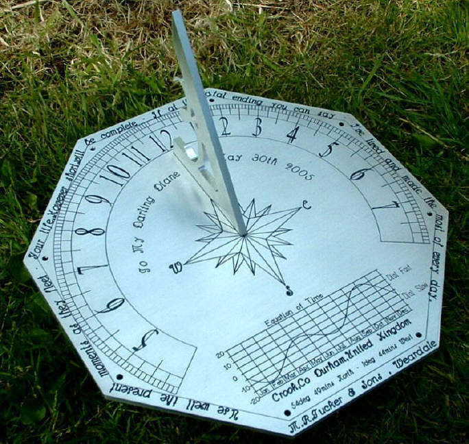
      0_1513689365865_382c70bc-e450-4cc8-89c9-f0cc3bd45522-image.png

      posted in General Discussion
      rmtucker
      rmtucker
    • RE: CNC PCB milling

      Carved this on my home made cnc router recently.
      Bit off topic but good fun.
      It is about 2ft diameter and 8" thick(old millstone)
      0_1513689287536_aa2a84b0-71ec-4d46-9c2d-f2241aa2827a-image.png

      posted in General Discussion
      rmtucker
      rmtucker
    • RE: CNC PCB milling

      @neverdie
      You have gone quietโ˜บ
      Must be beavering away cutting pcb's?

      posted in General Discussion
      rmtucker
      rmtucker
    • RE: CNC PCB milling

      @andrew
      I see.
      So what would be your best guess at your actual spindle rpm when cutting under your feed/depth of cut examples given above.?

      posted in General Discussion
      rmtucker
      rmtucker
    • RE: CNC PCB milling

      @andrew
      1000rpm for the spindle seems very slow,is that number correct?

      posted in General Discussion
      rmtucker
      rmtucker
    • RE: What did you build today (Pictures) ?

      @neverdie said in What did you build today (Pictures) ?:

      @sincze You could also put some salt into your tray for added conductivity when things get wet.

      Be very careful using salt,i killed an SI7021 doing something similar.
      I got up one morning and found the sensor covered in white fur and it was deadโ˜น

      posted in General Discussion
      rmtucker
      rmtucker
    • RE: ๐Ÿ’ฌ MySensors NRF5 Platform

      @neverdie
      Hmmm at what cost?
      Maybe i will stick with what i have got as it just works.โ˜บ

      posted in OpenHardware.io
      rmtucker
      rmtucker
    • RE: ๐Ÿ’ฌ MySensors NRF5 Platform

      @neverdie
      That explains it i am not using code from d00616.
      I am only using the mysensors library and sandeeps stuff.
      Sorry mate.

      posted in OpenHardware.io
      rmtucker
      rmtucker
    • RE: ๐Ÿ’ฌ MySensors NRF5 Platform

      @neverdie
      Where is myBoardNrf5 so i can check?

      posted in OpenHardware.io
      rmtucker
      rmtucker
    • RE: ๐Ÿ’ฌ MySensors NRF5 Platform

      @neverdie
      I have been using The NRF5 with mysensors for a number of weeks with the si7021.
      So it must be just a recent problem with the mysensors code?

      posted in OpenHardware.io
      rmtucker
      rmtucker
    • RE: ๐Ÿ’ฌ MySensors NRF5 Platform

      @NeverDie
      This is a test program that wakes up from either that i was using some time ago.

      /**
         The MySensors Arduino library handles the wireless radio link and protocol
         between your home built sensors/actuators and HA controller of choice.
         The sensors forms a self healing radio network with optional repeaters. Each
         repeater and gateway builds a routing tables in EEPROM which keeps track of the
         network topology allowing messages to be routed to nodes.
      
         Created by Henrik Ekblad <henrik.ekblad@mysensors.org>
         Copyright (C) 2013-2015 Sensnology AB
         Full contributor list: https://github.com/mysensors/Arduino/graphs/contributors
      
         Documentation: http://www.mysensors.org
         Support Forum: http://forum.mysensors.org
      
         This program is free software; you can redistribute it and/or
         modify it under the terms of the GNU General Public License
         version 2 as published by the Free Software Foundation.
      
       *******************************
      
         REVISION HISTORY
         Version 1.0 - Henrik EKblad
      
         DESCRIPTION
         This sketch provides an example how to implement a distance sensor using HC-SR04
         Use this sensor to measure KWH and Watt of your house meeter
         You need to set the correct pulsefactor of your meeter (blinks per KWH).
         The sensor starts by fetching current KWH value from gateway.
         Reports both KWH and Watt back to gateway.
      
         Unfortunately millis() won't increment when the Arduino is in
         sleepmode. So we cannot make this sensor sleep if we also want
         to calculate/report watt-number.
         http://www.mysensors.org/build/pulse_power
      */
      
      // Enable debug prints
      #define MY_DEBUG
      
      // Enable and select radio type attached
      //#define MY_RADIO_NRF24
      #define MY_RADIO_NRF5_ESB
      //#define MY_RADIO_RFM69
      //#define MY_RADIO_RFM95
      
      #include <MySensors.h>
      #include <Wire.h> // must be included here so that Arduino library object file references work
      #include <RtcDS3231.h>
      RtcDS3231<TwoWire> Rtc(Wire);
      
      #define DIGITAL_INPUT_SENSOR 2  // The digital input you attached your light sensor.  (Only 2 and 3 generates interrupt!)
      #define PULSE_FACTOR 1000       // Nummber of blinks per KWH of your meeter
      //#define SLEEP_MODE false        // Watt-value can only be reported when sleep mode is false.
      #define MAX_WATT 10000          // Max watt value to report. This filetrs outliers.
      #define CHILD_ID 1              // Id of the sensor child
      
      unsigned long SEND_FREQUENCY = 20000; // Minimum time between send (in milliseconds). We don't wnat to spam the gateway.
      double ppwh = ((double)PULSE_FACTOR) / 1000; // Pulses per watt hour
      //bool pcReceived = false;
      volatile unsigned long pulseCount = 0;
      volatile unsigned long lastBlink = 0;
      volatile unsigned long watt = 0;
      volatile unsigned long kwh = 0;
      unsigned long oldWatt = 0;
      double oldKwh;
      unsigned long lastSend;
      MyMessage wattMsg(CHILD_ID, V_WATT);
      MyMessage kwhMsg(CHILD_ID, V_KWH);
      
      
      void setup()
      {
        Serial.begin(115200);
        Rtc.Begin();
        Rtc.Enable32kHzPin(false);
        Rtc.SetSquareWavePinClockFrequency(DS3231SquareWaveClock_1Hz);
        Rtc.SetSquareWavePin(DS3231SquareWavePin_ModeClock);
      
        // Use the internal pullup to be able to hook up this sketch directly to an energy meter with S0 output
        // If no pullup is used, the reported usage will be too high because of the floating pin
        hwPinMode(DIGITAL_INPUT_SENSOR, INPUT_PULLUP);
      
        attachInterrupt(digitalPinToInterrupt(DIGITAL_INPUT_SENSOR), onPulse, FALLING);
        //pcReceived = true;
        lastSend = millis();
      }
      
      void presentation()
      {
        // Send the sketch version information to the gateway and Controller
        sendSketchInfo("Energy Meter", "1.0");
      
        // Register this device as power sensor
        present(CHILD_ID, S_POWER);
      }
      
      void loop()
      {
        unsigned long now = millis();
        // Only send values at a maximum frequency or woken up from sleep
        bool sendTime = now - lastSend > SEND_FREQUENCY;
        if (sendTime) {
          // New watt value has been calculated
          if (watt != oldWatt) {
            // Check that we dont get unresonable large watt value.
            // could hapen when long wraps or false interrupt triggered
            if (watt < ((unsigned long)MAX_WATT)) {
              send(wattMsg.set(watt));  // Send watt value to gw
            }
            Serial.print("Watt:");
            Serial.println(watt);
            oldWatt = watt;
          }
      
          // Pulse count has changed
          //kwh = pulseCount;
          //double kwh = ((double)pulseCount / ((double)PULSE_FACTOR));
          send(kwhMsg.set(pulseCount));  // Send kwh value to gw
          Serial.print("Wh = ");
          Serial.println(pulseCount);
          pulseCount = 0;
          lastSend = now;
        }
        sleep(SEND_FREQUENCY);
      }
      
      void receive(const MyMessage &message)
      {
      }
      
      void onPulse()
      {
        unsigned long newBlink = micros();
        unsigned long interval = newBlink - lastBlink;
        if (interval < 50000L) { // Sometimes we get interrupt on RISING
          return;
        }
        watt = (3600000000.0 / interval) / ppwh;
        lastBlink = newBlink;
        pulseCount++;
      }
      
      posted in OpenHardware.io
      rmtucker
      rmtucker
    • RE: ๐Ÿ’ฌ Multi-Sensor: Temp/Humidity/PIR/ Leak/Magnet/Light/Accel

      @DerManni

      STLink<----------------->NRF

      SWCLK<--------------->SWD
      SWDIO<---------------->SWIO
      3.3v<--------------------->3.3v
      GND<-------------------->GND

      posted in OpenHardware.io
      rmtucker
      rmtucker
    • RE: ๐Ÿ’ฌ Multi-Sensor: Temp/Humidity/PIR/ Leak/Magnet/Light/Accel

      @NeverDie
      Yes i am using the STLink v2 without any problems.

      posted in OpenHardware.io
      rmtucker
      rmtucker
    • RE: ๐Ÿ’ฌ MySensors NRF5 Platform

      @scalz
      So the statement
      int8_t sleep(int interrupt, int mode, unsigned long ms=0);
      Can be used for timer and pin interrupt at he same time on the NRF5 platform just like the arduino?

      posted in OpenHardware.io
      rmtucker
      rmtucker
    • RE: ๐Ÿ’ฌ MySensors NRF5 Platform

      @NeverDie

      So we can not use the normal statement

      int8_t sleep(int interrupt, int mode, unsigned long ms=0);

      I did not realize that was the case as i have never tried it.

      posted in OpenHardware.io
      rmtucker
      rmtucker
    • RE: Why do "passive nodes" need to set their Node ID manually?

      @NeverDie
      Just cut domoticz out of the picture as node-red/influx/grafana works perfect with any gateway serial/ethernet/mqtt.
      I prefer the serial gateway in my own experience is the most stable and no reliance on wifi routers and things.
      Domoticz has nowhere near the same flexibility when graphing etc.

      posted in General Discussion
      rmtucker
      rmtucker
    • RE: nRF5 action!

      @NeverDie said in nRF5 Bluetooth action!:

      @NeverDie said in nRF5 Bluetooth action!:

      I'm realizing now that I can get a decent temperature reading from just the nRF5x chip itself. With calibration it should get even better.

      I used the internal temperature in the past but i can not remember how i did it?
      Do you have some example code to remind me?

      posted in My Project
      rmtucker
      rmtucker
    • RE: nRF5 action!

      @NeverDie
      That would be perfect but i would have to order everything from china.
      Well maybe not the led and resistor.
      I also prefer the si7021 also it has far less consumption and quite accurate.

      posted in My Project
      rmtucker
      rmtucker
    • RE: nRF5 action!

      @NeverDie
      Its just the waveshare ble400 board but i have cut one of the tracks to prevent the residual drain from the on board regulator.
      And i have an external cr2032 battery holder feeding it.
      I would love to make a small pcb for the NRF core to plug in to instead of the big motherboard as below, but i failed dismally at the design side of things.

      0_1509571898531_upload-00d6665f-f065-4ed7-927d-2a5e27224fc6

      posted in My Project
      rmtucker
      rmtucker
    • RE: nRF5 action!

      Well my NRF51822 has been running 25days approx sending every 60secs on a cr2032.
      No signs of problems yet.
      0_1509561715247_upload-e21e5fcc-113b-4d47-bd54-7d7d89841bf9

      posted in My Project
      rmtucker
      rmtucker
    • RE: nRF5 action!

      @NeverDie
      Yes Node-red is the controller which is saving data into influxdb and then displaying the data in grafana.
      But i am also using the node-red dashboard for any actuator nodes etc as grafana is really just for viewing the data.

      posted in My Project
      rmtucker
      rmtucker
    • RE: nRF5 action!

      Plugged my NRF51822 board into a cr2032 button battery and it is sending voltage/Rssi/Random Temperature every 1min.
      Just to see how low it goes and how long.
      I also changed my controller over to Grafana and influxdb/Node-red.
      So far i am suitably impressed.
      0_1507487097966_upload-850da6d9-bef1-46b4-a78a-74768b8866de

      0_1507487255056_upload-cd17d1f5-6a36-4932-8804-966205e286eb

      posted in My Project
      rmtucker
      rmtucker
    • RE: nRF5 action!

      @NeverDie
      I am puzzled with your 596ua?
      I thought you were under 10ua with the mysensors sleep some time ago?
      Mine only measures 4-5ua when in sleep?

      posted in My Project
      rmtucker
      rmtucker
    • RE: nRF5 action!

      @NeverDie
      /variants/Generic/variant.h i think

      posted in My Project
      rmtucker
      rmtucker
    • RE: nRF5 action!

      Just wondering if ota updates are possible with the nrf5 because it does not have the usual memory constraints?

      posted in My Project
      rmtucker
      rmtucker
    • RE: nRF5 action!

      @NeverDie
      Sorry mate i have deleted it i am just a little miffed with the controller searching๐Ÿ˜ 

      posted in My Project
      rmtucker
      rmtucker
    • RE: nRF5 action!

      @NeverDie
      I am a little lost with this,I am using sleep and wake from ext int on the nrf51 and it has been working every second for the last 2 weeks.
      What kind of int are you trying to implement?

      posted in My Project
      rmtucker
      rmtucker
    • RE: How to get time a sensor has slept

      Or use the Nrf5 which can keep time while sleeping ๐Ÿ˜‰

      posted in Troubleshooting
      rmtucker
      rmtucker
    • RE: nRF5 action!

      @NeverDie
      Theoretically it is 2 clock ticks at 32768khz so 0.000061035secs i think.
      But how long it takes to go into sleep mode and come out of sleep mode i am not sure.
      But of course the sleep function only allows millis.

      posted in My Project
      rmtucker
      rmtucker
    • RE: nRF5 action!

      @NeverDie said in nRF5 Bluetooth action!:

      Epilog: I made the changes so that just prior to taking a measurement the sense pin is hwPinMode'd to an input pin, and then immediately after the measurement I disconnect it. Seems to be working, and without the usurious power drain I was experiencing previously. ๐Ÿ™‚

      Good news
      So what is the current usage now when sleeping?

      posted in My Project
      rmtucker
      rmtucker
    • RE: nRF5 action!

      @d00616

      Just checked and it now returns 10002 for a sleep(10000).
      Much better after the above alteration.

      posted in My Project
      rmtucker
      rmtucker
    • RE: nRF5 action!

      @d00616

      MY_HW_RTC->CC[0] = max((ms<<12 / 125), 2);

      Should be:-

      MY_HW_RTC->CC[0] = max(((ms << 12) / 125), 2));

      posted in My Project
      rmtucker
      rmtucker
    • RE: nRF5 action!

      The only other thing it could be is the deletion of this line in the commit.

      
      nrf5_rtc_event_triggered = false 
      
      posted in My Project
      rmtucker
      rmtucker
    • RE: nRF5 action!

      The problem must be this line but i don't speak nrf5.๐Ÿ˜ฆ

      			// (1000/32768)<<12 == 125
      			MY_HW_RTC->CC[0] = max((ms<<12 / 125), 2);```
      posted in My Project
      rmtucker
      rmtucker
    • RE: nRF5 action!

      Try it just print the time out then put it to sleep for a minute then print the time out again.

      posted in My Project
      rmtucker
      rmtucker
    • RE: nRF5 action!

      @NeverDie
      No the nrf5 has a rtc.(Real time Counter)
      It can even keep time while sleeping.(just found this out myself!).
      That is a great leap forward on the arduino.

      posted in My Project
      rmtucker
      rmtucker
    • RE: nRF5 action!

      something wrong in here:-

      // Calculate sleep time and prescaler
      		if (ms<512000) {
      			// prescaler 0, 30.517 ฮผs resolution -> max 512 s sleep
      			MY_HW_RTC->PRESCALER =  0;
      			// Set compare register to 1/30.517 ยตs to garantee event triggering
      			// A minimum of 2 ticks must be guaranteed
      			// (1000/32768)<<12 == 125
      			MY_HW_RTC->CC[0] = max((ms<<12 / 125), 2);
      		} else {
      			// 8 Hz -> max 582.542 hours sleep.
      			MY_HW_RTC->PRESCALER = 4095;
      			// Set compare register to 1/125ms
      			// A minimum of 2 ticks must be guaranteed
      			MY_HW_RTC->CC[0] = max((ms / 125), 2);
      		}
      
      posted in My Project
      rmtucker
      rmtucker
    • RE: nRF5 action!

      @NeverDie said in nRF5 Bluetooth action!:

      @rmtucker
      How are you measuring how long it's sleeping?

      Just using hwMillis() before and after sleep and subtracting one from the other.
      It was just reading + 250ms until @d00616 commited some changes a few hours ago.

      posted in My Project
      rmtucker
      rmtucker
    • RE: nRF5 action!

      @d00616 said in nRF5 Bluetooth action!:

      @rmtucker said in nRF5 Bluetooth action!:

      Yes being able to change the prescaler dynamically would help a great deal as 125ms / 582.542 hours is not really useful for most applications with a 250ms overrun.

      The sleep() function is now more precise for sleeping <512s:

      https://github.com/mysensors/MySensors/pull/909

      The PR is waiting for merge.

      Hmm just tried the latest commit and it is giving me 306ms for sleep(10000).
      Something not quite right.

      posted in My Project
      rmtucker
      rmtucker
    • RE: nRF5 action!

      @NeverDie
      He has not added that facility yet,i think he asked you if you wanted it adding to the code?

      posted in My Project
      rmtucker
      rmtucker
    • RE: nRF5 action!

      @NeverDie
      Should be

      hwPinMode(DIGITAL_INPUT_SENSOR, INPUT_PULLUP);
      

      According to NRF5 platform

      posted in My Project
      rmtucker
      rmtucker
    • RE: nRF5 action!

      @NeverDie

      Stranger still my 4-5uA is using the external crystal??.

      posted in My Project
      rmtucker
      rmtucker
    • RE: nRF5 action!

      @NeverDie
      I can not understand why you are drawing 9.4uA in the first place?.
      My nrf51822 seems to consistently only draw 4-5uA with no strip down of software when in mysensors sleep mode.
      Fair enough i have not got your measurement equipment but i don,t see it being that far away.
      The data sheets seem to point to under 5uA.

      posted in My Project
      rmtucker
      rmtucker
    • RE: nRF5 action!

      @NeverDie
      So your sketch only wakes up every 12hours.
      What current is it drawing using the radiohead library vs mysensors for an equivalent 12 hour sleep because in past discussions with you i remember you saying 5-6uA while sleeping,is this still correct?
      I dont see much advantage to the radiohead library if only sending at 12hour intervals.

      posted in My Project
      rmtucker
      rmtucker
    • RE: nRF5 action!

      Just wondering what the prescaler etc would have to be set to for ms accuracy and how long before overflow.(aint got my maths head on today)๐Ÿ˜Š

      posted in My Project
      rmtucker
      rmtucker
    • RE: nRF5 action!

      @d00616
      My initial thoughts were how the nrf51822 could be used for energy meters (counting pulses and the gap between them),But unlike the arduino's which can not run timers when in sleep mode,The nrf5 can of course do this.
      So the nrf5 would be able to report watts and usage while still using sleep mode.
      But seeing the inaccuracy of the timer has put the brakes on that.
      Yes being able to change the prescaler dynamically would help a great deal as 125ms / 582.542 hours is not really useful for most applications with a 250ms overrun.

      posted in My Project
      rmtucker
      rmtucker
    • RE: nRF5 action!

      @NeverDie
      Seeing Your sketch would help?

      posted in My Project
      rmtucker
      rmtucker
    • RE: nRF5 action!

      MY_HW_RTC->CC[0] = (ms / 125) + 2;

      It seems the +2 above is adding 250ms.
      Why is it done like this???

      posted in My Project
      rmtucker
      rmtucker
    • RE: nRF5 action!

      Seems it may have something to do with this in the code.

      // Calculate sleep time
      		// 8 Hz -> max 582.542 hours sleep.
      		MY_HW_RTC->PRESCALER = 4095;
      		// Set compare register to 1/125ms + 2 to garantee event triggering
      		MY_HW_RTC->CC[0] = (ms / 125) + 2;```
      posted in My Project
      rmtucker
      rmtucker
    • RE: nRF5 action!

      I was playing with sleep tonight and found the following problem.
      when using sleep as below it always returns a figure 252 ms bigger than the sleep figure.
      ie sleep 10000 always returns 10251
      ie sleep 3000 always returns 3251.
      I know the nrf51822 has a 32khz rtc so why is this?

        oldmillis = hwMillis();
        hwSleep(10000);
        newmillis = hwMillis();
        Serial.println(newmillis - oldmillis);
      
      posted in My Project
      rmtucker
      rmtucker
    • RE: ๐Ÿ’ฌ MySensors NRF5 Platform

      @d00616
      So should i be able to delete the hardware folder that the development version created from github and just update from boards manager?.

      posted in OpenHardware.io
      rmtucker
      rmtucker
    • RE: nRF5 action!

      @NeverDie
      Part number?

      posted in My Project
      rmtucker
      rmtucker
    • RE: nRF5 action!

      @NeverDie
      Hmm the only 2.7v ldo i can see are surface mount in the uk.
      Thats a no no for me.

      posted in My Project
      rmtucker
      rmtucker
    • RE: nRF5 action!

      @NeverDie
      My Mistake but his results were impressive don't you think?
      Anyway i was just going to use 4f because i can get one.
      How are you charging your Cap?

      posted in My Project
      rmtucker
      rmtucker
    • RE: nRF5 action!

      @NeverDie
      Nick Gammon experiments

      posted in My Project
      rmtucker
      rmtucker
    • RE: nRF5 action!

      @NeverDie
      I think he was using an nrf24 just the same as us.
      He was getting 32hours without re-charging and transmitting every 5mins.

      posted in My Project
      rmtucker
      rmtucker
    • RE: nRF5 action!

      @rmtucker
      On the supercapacitor subject.
      Nick Gammon used a 0.47uf 5.5v capacitor and you have been trying a 10uf 2.7v.
      So i was going to try a 4uf 5.5v super cap and an mcp1700-33 to power the nrf at 3.3v.
      I was going to charge the supercap initially with an adjustable dc-dc converter set to 5v while experimenting,anyone see a problem?

      posted in My Project
      rmtucker
      rmtucker
    • RE: nRF5 action!

      @rmtucker
      I did eventually manage to stop it by putting it in the fridge.
      My other half has never laughed so much.๐Ÿ˜ƒ๐Ÿ˜ƒ

      posted in My Project
      rmtucker
      rmtucker
    • RE: nRF5 action!

      @NeverDie
      What are you using at the other end,just a standard nrf24 or the amplified version.
      I switched to rfm69 some time ago because of poor range/coverage.
      But i am astounded with the nrf51 and wemos/nrf24 pa setup.
      Maybe it is the tin foil wrapping Lol.๐Ÿ˜ƒ

      posted in My Project
      rmtucker
      rmtucker
    • RE: nRF5 action!

      Out of curiosity i stuck a cake tin over the top of the node and it just carried on transmitting,so i put it behind 4 walls and 1 floor down then behind the fuse box and consumer unit and eventually got it to drop to -68dB for received rssi but send rssi stayed at -45dB so it seems to be booming out and in.๐Ÿ˜‰

      posted in My Project
      rmtucker
      rmtucker
    • RE: nRF5 action!

      @scalz said in nRF5 Bluetooth action!:

      I don't think sendSignalStrength function is implemented yet, but you should be able to get this info with:

      int16_t transportGetSendingRSSI(void)
      int16_t transportGetReceivingRSSI(void)
      

      Just wondering what both of these mean?
      I assumed the transportGetReceivingRSSI(void) was the strength of signal from my Gateway ?
      But what is the transportGetSendingRSSI(void)?

      posted in My Project
      rmtucker
      rmtucker
    • RE: nRF5 action!

      Just in case anyone uses the waveshare ble400 board.
      The board was consuming 150uA when fed with 3.3v bypassing the regulator.
      I have cut through one of the tracks and now it is only consuming 4-5uA and it can still be used normally with the usb lead 5v as long as i place a dupont link across 2 pins.
      If anyone needs photo's let me know.

      posted in My Project
      rmtucker
      rmtucker
    • RE: nRF5 action!

      @NeverDie said in nRF5 Bluetooth action!:

      @rmtucker said in nRF5 Bluetooth action!:

      @NeverDie
      I connected a new amplified nrf24 to the gateway with the tin foil as mentioned and it is reading -60dB compared to -89dB with the non amplified version.

      Did the tin foil make a difference? Hackaday seemed to think it made a big difference. I haven't tried it yet.

      I think it did but what do you have to lose๐Ÿ˜‰

      posted in My Project
      rmtucker
      rmtucker
    • RE: nRF5 action!

      @rmtucker
      Well outside of the garden now no problem.๐Ÿ˜Š
      On to supercaps now i think.๐Ÿ˜‰

      posted in My Project
      rmtucker
      rmtucker
    • RE: nRF5 action!

      @NeverDie
      I connected a new amplified nrf24 to the gateway with the tin foil as mentioned and it is reading -60dB compared to -89dB with the non amplified version.
      Now lets see how far it goes past the original test.๐Ÿ˜‰

      posted in My Project
      rmtucker
      rmtucker
    • RE: ๐Ÿ’ฌ Micro (nano) ampere meter (double)

      @Nca78 said in ๐Ÿ’ฌ Micro (nano) ampere meter (double):

      @rmtucker said in ๐Ÿ’ฌ Micro (nano) ampere meter (double):

      I am confused the 1k resistors seem to be wired differently in AWI photo's and Nca78 photo's.
      I would like to build this but not certain how it is wired now

      If you do like drawn on my post from July 7, it works.

      Are the blue and green resistors you have drawn on the back of the adc module the 1k resistors?
      Have you soldered them on the other side?

      posted in OpenHardware.io
      rmtucker
      rmtucker
    • RE: ๐Ÿ’ฌ Micro (nano) ampere meter (double)

      I am confused the 1k resistors seem to be wired differently in AWI photo's and Nca78 photo's.
      I would like to build this but not certain how it is wired now

      posted in OpenHardware.io
      rmtucker
      rmtucker
    • RE: nRF5 action!

      @d00616 said in nRF5 Bluetooth action!:

      I have checked the current with my nRF52 board with integrated shunt. I have measured 6.5ยตA while sleeping until timeout or sleeping until interrupt. It doesn't matter if RX/TX are connected but after flashing the firmware a reset by removing the voltage is required.

      Does the onboard regulator on this board not draw any current when not being used?
      ie when feeding the board with 3.3v and bypassing the regulator?

      posted in My Project
      rmtucker
      rmtucker
    • RE: nRF5 action!

      At the moment i am range testing.
      I have the nrf51822 sending v_status true then false every second.
      The esp8266 gateway recieves it and sends it back to the nrf8122 which turns an led on and off accordingly.
      I have the nrf8122 running from a usb powerbank so i can walk around my house.
      There are a few deadspots around the house with the unamplified nrf24l01 on the gateway.
      I tried my nrf24l01 pa lna sma but it seemed to be only working every now and again so waiting on a new one being delivered.

      posted in My Project
      rmtucker
      rmtucker
    • RE: How to graph datapoints more often than once every 5 minutes?

      @NeverDie said in How to graph datapoints more often than once every 5 minutes?:

      @rmtucker
      Which different controller do you recommend?

      I Am using myHouse at the moment.

      posted in Domoticz
      rmtucker
      rmtucker
    • RE: How to graph datapoints more often than once every 5 minutes?

      @NeverDie

      You cant not in Domoticz thats why i don't use it.
      You can push the data to influxdb and look at it using Grafana i believe.
      But to me it is A NUISANCE.
      Better off using another controller if you want more detail.

      posted in Domoticz
      rmtucker
      rmtucker
    • RE: nRF5 action!

      @NeverDie
      When you are comparing the atmega 328 and the nrf52 what sketch are you using to come to your conclusions?.

      posted in My Project
      rmtucker
      rmtucker
    • RE: nRF5 action!

      So range test.
      Using esp8266 with standard nrf24 not amplified gateway at one end of the house.
      Nrf51822 node in garage which is not fastened to house so at a guess 15m through 3 brick walls is reporting -86db.
      I think that is quite respectable.;-)

      posted in My Project
      rmtucker
      rmtucker
    • RE: nRF5 action!

      @scalz
      Rssi works really well.
      Thank you.

      posted in My Project
      rmtucker
      rmtucker
    • RE: nRF5 action!

      Is RSSI reporting implemented in the NRF5 setup yet?
      If so how is it done?

      posted in My Project
      rmtucker
      rmtucker
    • RE: nRF5 action!

      @NeverDie
      As mentioned earlier by someone the nrf52 is preset to 0.6v internal ref and a 1/5 divider so 0 - 3v is the max input so your calculation is correct.
      The nrf51 is different because the ref can be set to a few different settings but the default is vdd.

      posted in My Project
      rmtucker
      rmtucker
    • RE: How do I get multiple different mock barometers?

      @NeverDie
      Ye i just like all the settings at the beginning of my sketches etc,it reminds me if i have changed channel number etc.

      posted in Development
      rmtucker
      rmtucker
    • RE: nRF5 action!

      Could anyone tell me why the waveshare board is pulling 140uA when sleeping with everything unpugged including the usb and all the header jumpers so only 3.3v and ground fed to the header pins so not using the regulator etc.
      I have attached a link to the schematic hoping some circuit wiz might be able to explain.
      link text

      If i unplug the core board and just power that with 3.3v and gnd it only uses 5uA when sleeping.

      posted in My Project
      rmtucker
      rmtucker
    • RE: How do I get multiple different mock barometers?

      @NeverDie

      Here is a little sketch that compiles on the NRF5.

      // Enable debug prints to serial monitor
      //#define MY_DEBUG
      
      // Enable and select radio type attached
      #define MY_RADIO_NRF5_ESB
      
      /**
         @def MY_NRF5_ESB_PA_LEVEL
         @brief Default nRF5 PA level. Override in sketch if needed.
      
         - NRF5_PA_MIN = -40dBm
         - NRF5_PA_LOW = -16dBm
         - NRF5_PA_HIGH = 0dBm
         - NRF5_PA_MAX = 4dBm
      */
      #define MY_NRF5_ESB_PA_LEVEL (NRF5_PA_MAX)
      
      #define MY_NRF5_ESB_CHANNEL (76)
      
      #define MY_NRF5_ESB_MODE (NRF5_250KBPS)
      
      #define MY_NODE_ID 10
      #define VOLTAGE     0
      #include <MySensors.h>
      
      float vcc = (hwCPUVoltage() / 1000.0);
      
      MyMessage VoltageMsg(VOLTAGE, V_VOLTAGE);
      
      void presentation()
      {
        sendSketchInfo("General sensor", "1.0");
        present(VOLTAGE, S_MULTIMETER);
      }
      
      
      void setup() {
      //  Serial.begin(115200);
      //  while (!Serial) ; // wait for Arduino Serial Monitor
      }
      
      void loop() {
        send(VoltageMsg.set(vcc, 3));
      //  Serial.print(F("Voltage = "));
      //  Serial.print(vcc, 3);
      //  Serial.println(F("v"));
        sleep(60000);
      }
      
      
      posted in Development
      rmtucker
      rmtucker
    • RE: How do I get multiple different mock barometers?

      @NeverDie
      Why barometer instead of voltage and multimeter?

      posted in Development
      rmtucker
      rmtucker
    • RE: nRF5 action!

      @Toyman
      Yes i am already running that board at the moment.
      But that board consumes around 140uA when sleeping.
      It must be the extra electronics like the regulator and uart.
      even when feeding the core board with 3.3v directly.
      When the core board is on its own it only measures 5uA when sleeping.

      posted in My Project
      rmtucker
      rmtucker
    • RE: nRF5 action!

      @NeverDie

      What you using for pcb design?
      I would like to design something for the waveshare core board to plug into similar to what you just designed for the nrf52832 modules to adapt to 2.54mm pitch headers.
      0_1502221830970_upload-3b01b675-529e-4554-8142-f232a7d3e827

      Similar to what you did here but with two sockets on top for the waveshare board.
      https://www.openhardware.io/view/436/nRF52832-Breakout-Board

      posted in My Project
      rmtucker
      rmtucker