MySensor Network on RS485 - only single node visible
-
@Rysiek As you are using a Pro Micro as a GW, imo the RS485 modules should be connected to Serial1 instead of Serial (which goes to USB).
@rejoe2 said in MySensor Network on RS485 - only single node visible:
@Rysiek As you are using a Pro Micro as a GW, imo the RS485 modules should be connected to Serial1 instead of Serial (which goes to USB).
Hi, well actually it is Serial1, Serial will not compile on pro Micro, I was trying to use nano as gateway, but it took no effect. the code I pasted is from that. in Pro Micro Gateway it is of course Serial1.
-
OK, so thanks for info.
Some additional remarks:
- using a GW also as a sensor node might cause trouble, too. I'd recommend to avoid that (though it's possible, no question). This recommendation is even stronger here, because reading DS18B20 might be blocking for short periods of time (see "conversion time").
- That conversion time may be an additional point to look at at the GW node. Didn't do investiagations on that, but your measurement might not deliever reliable results due to lack of delay.
- In general, I'd also recommend to use non-blocking-loops for all central powered nodes. Putting the nodes 1 and 2 to sleep or let them "delay" for longer periods might also cause trouble. Better start with "dumb" messages (e.g. send a "tripped" message every 30 seconds) to test if your problems are more on the physical communication layer or on the software/firmware side.
-
Hi,
Thank you for your comments. it gave me a little thinking and I guess I will remove temp sensor from gateway.
Also I will not put them into sleep... I will try to check what effect will I get when I put some nodes to sleep for that 30 minutes. (BTW what kind of trouble you have in mind?). From my perspective putting nodes to sleep will save some power. I can of course "wake" them every 30 seconds for loop or two :P.Anyway, I tried to do as you suggested, and find out that effect will be the same... node 2 is somehow blocking node 1 communication and when node 2 is connected node 1 is not visible.
BUT... while testing is I have a thought of possible reason. Node 2 and the gateway are using HW serial for communication while node 1 is using software library. I've made another node on prototype board and connected it to the bus... and both node 2 and new node 3 were visible (no 1 was not). I will made PCB and try to replace node1 with HW serial communication.
Let you know if it works.Regards
@Rysiek In general, I don't see any problem in mixing softwareserial and hardwareserial (I did that in the past, too).
Wrt. to sleep: My entire RS485-MySensors-setup consumes ~3W (dependent on relay states), so powering down the arduinos most likely will save some power, yes; but imo that's negilable.
What might happen when powering down: the bus might get blocked, if one of the nodes keeps bus on "high" level. I had some nasty problems wrt to that, so I make sure, there is nothing (slightly) suspective of such behaviour (additionally, I changed the RS485 Modules with CAN ones (MCP2551) - they don't need no DE/RE/interrupt, too and can be used as a drop-in-replacement. The only disadvantage: they are not PIN-compatible when using SOIC-8 variants, so you can't use most of the board designs from openhardware.io). -
@rejoe2 Hi, Thank for description. I'm a little confused with this HW/SW serial, because I've also mixed them while building prototypes and it worked. Today I'm going to test it once again. I've already build node using HW serial and later today going to replace old one. We'll see how it will work.
As for CAN.. well I have to read more about it, lacking compatibility with existing PCBs is not a problem, I used to build my own PCBs.
-
You should use terminating resistors on both ends. But also try to add or change resistor(10k) between A to VCC and B to GND. It's R5 and R6 on schematic.
-
@Jarosław-Narbut What do you mean by "changing resistors" as they already exists... what values do you propose??
Anyway, when I've replace node that used SW for serial communication with HW one, the problem is gone.
Regards
Ryszard -
@Jarosław-Narbut What do you mean by "changing resistors" as they already exists... what values do you propose??
Anyway, when I've replace node that used SW for serial communication with HW one, the problem is gone.
Regards
Ryszard@Rysiek said in MySensor Network on RS485 - only single node visible:
@Jarosław-Narbut What do you mean by "changing resistors" as they already exists... what values do you propose??
Anyway, when I've replace node that used SW for serial communication with HW one, the problem is gone.
Regards
Ryszard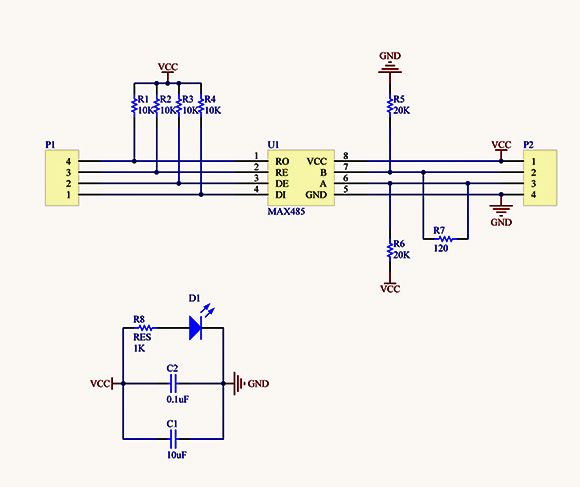
R5 and R6 change or add to 10k.I have 11 nodes with SW serial, 1 with HW, and GW mqtt with HW. RS485 speed set to 57600kbps.
-
@Jarosław-Narbut , thanks I will try that.
-
Having a deeper look at resistor values is always a good idea.
Indeed, optimal values depend on a lot of parameters. You might find a helpful tool for getting the best values for your setup here: http://www.alciro.org/tools/RS-485/RS485-resistor-termination-calculator.jsp -
Very useful topic for me, thanks. Even though it's been a long time, the information was useful to me. And especially the information on the link you sent.
Hello! It looks like you're interested in this conversation, but you don't have an account yet.
Getting fed up of having to scroll through the same posts each visit? When you register for an account, you'll always come back to exactly where you were before, and choose to be notified of new replies (either via email, or push notification). You'll also be able to save bookmarks and upvote posts to show your appreciation to other community members.
With your input, this post could be even better 💗
Register Login