implementing multiple sensors
-
Probably not the easiest to look at since it combined a RGB diode and RFID reader. But it works very well.
https://github.com/wbcode/ham/blob/master/arduino/MySensorRFIDandRGB/RGBandRFID/RGBandRFID.inoI should add that I don't use the Vera as a controler.
WB
-
I have been working on one that combines a servo, temperature and light sensor. I have had it running for a while now. I have been busy lately and have not really had time to write it up and post it. I am attaching what I have, maybe it would help or give some ideas.
[Servo-Light-Temp-Sensors.zip](uploading 100%).zip did not take here are the files
-
If i was a programmer... i would write a wizard app/script/webpage that would ask a user a bunch of questions..
- What Arduino are they using.
- what sensors/actuators they want to have on their sketch
- what pins ( showing those available) are they going to connect the sensor to.
- What they want to call the sketch
- Relay mode?
- Sampling times
etc etc
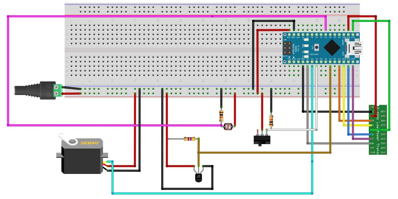
if i was a really good programmer, i would produce a schematic/frizing like above ;-)
Unfortunately in not a programmer..really wish i was, and am trying to get there slowly...so if you guys are cool with waiting another 5 years ill get something together...
-
We've actually thought about doing a sketch-generator also. It's down there on the list. And it would be a web-thing (hopefully with OTA update) :)
-
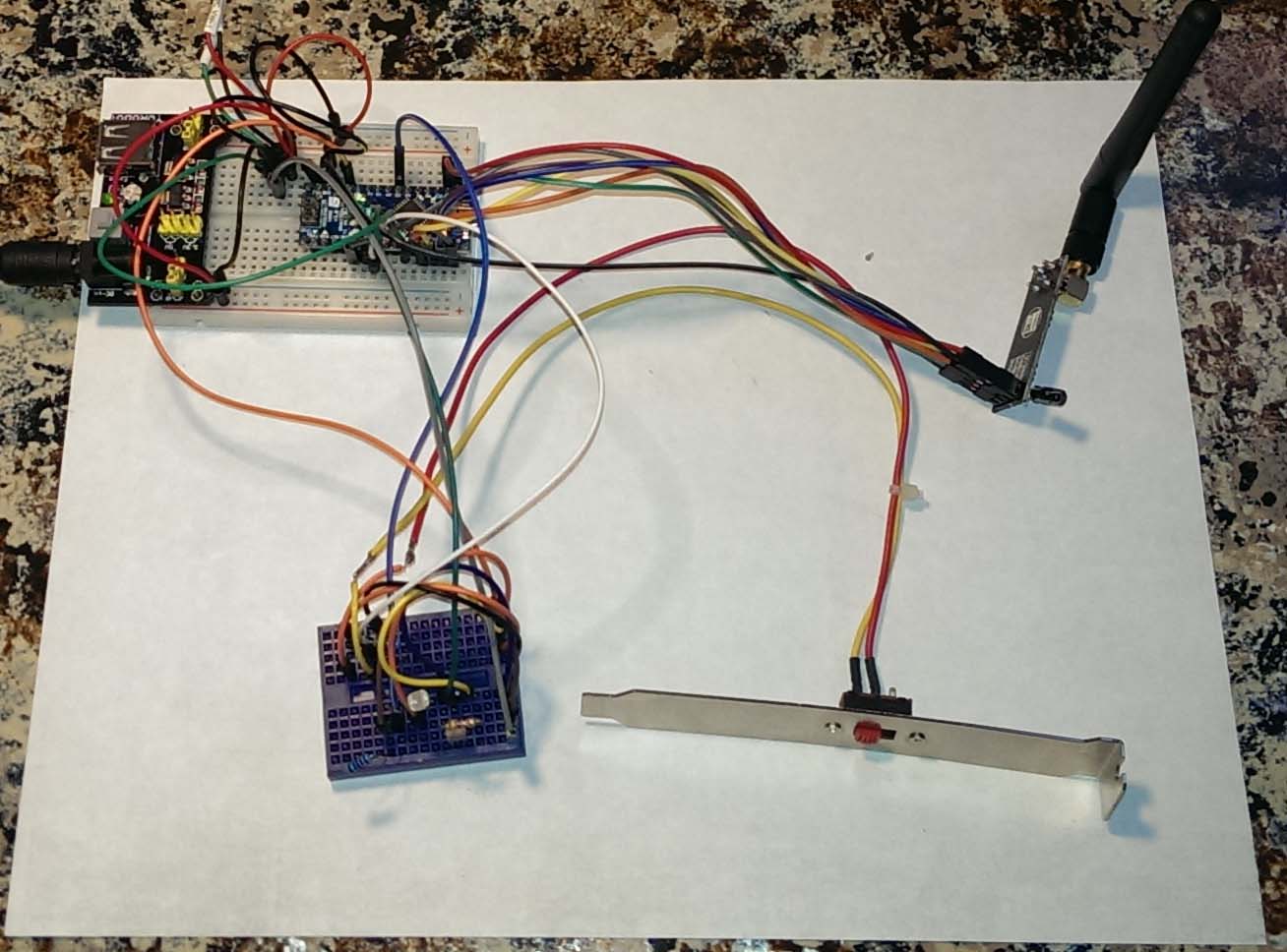
A few people have asked about the hardware I used.
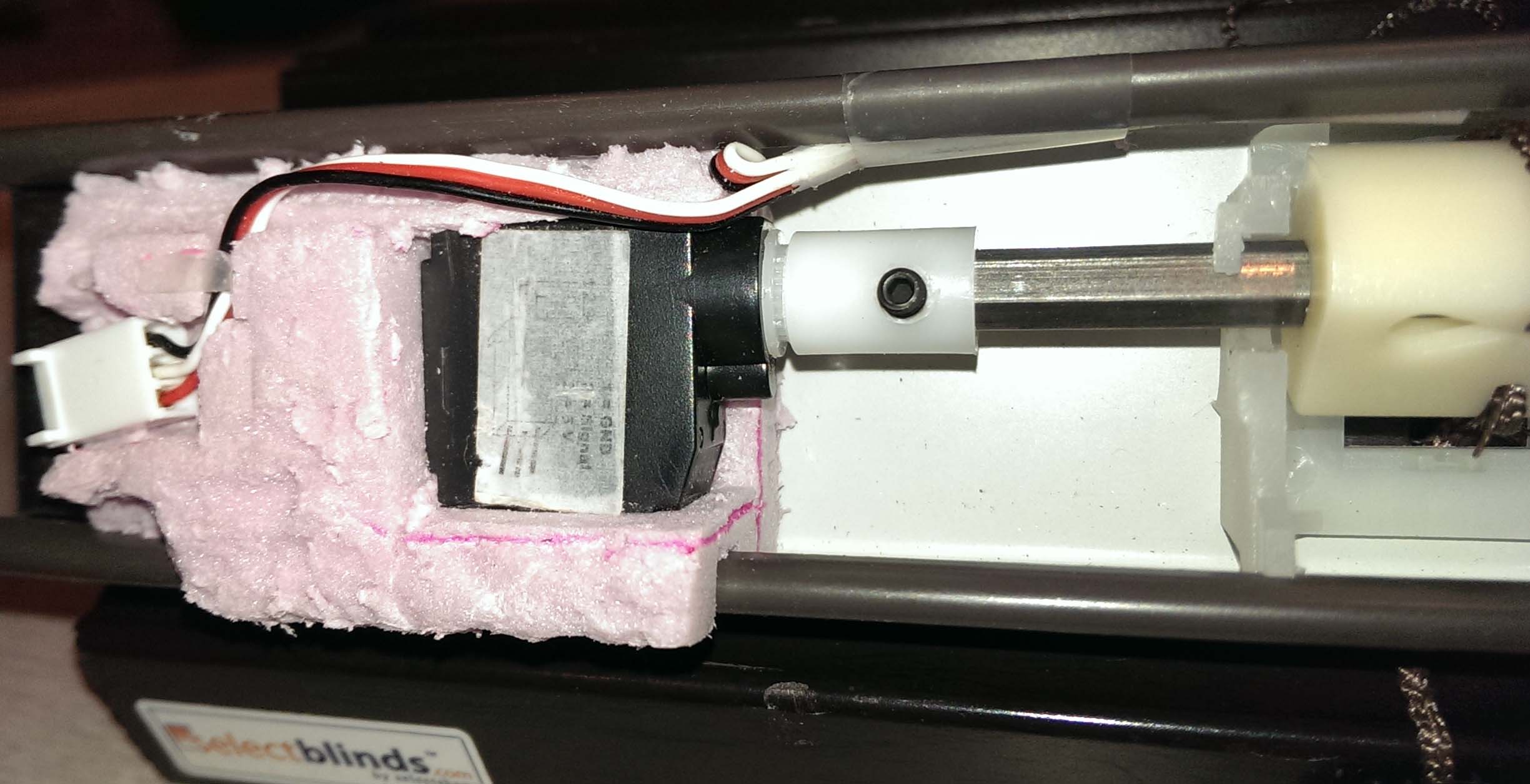
A quick write up on what hardware I used for the blinds-light-temp-servo project.
My binds are 1” not the 2” that you see in the projects listed in the forums. The standard servos will not fit inside the 1” blinds, so I had to use the mini servos. My concern was that the mini servos would not have the torque necessary to operate the tilt mechanism. But for at least the 45x38 blinds I have the mini servo worked great, not sure about larger size blinds.
I removed the tilt wand and mechanism completely and connected the servo directly to the hex rod. I used a piece of 2” foam insulation and cut out a cavity for the servo and used it as the mounting bracket.
I purchased a Nano IO shield from imall.iteadstudio.com, which I plan to use when I assemble the parts into a final enclosure and mount it inside the cabinet. With the Light and Temp sensors mounted inside the window frame.
I use PLEG to control the blinds.
Parts used:
http://www.ebay.com/itm/291084936296?ssPageName=STRK:MEWAX:IT&_trksid=p3984.m1423.l2649 – used to connect the servo to the hex rod. Note I had to cut off some of the hex rod so the servo would sit inside the head rail.
I tried to upload a 5 second video of the binds in operation, but the file is too large.
-
Two short videos
- During development
- In production
http://tinypic.com/r/2dcfn9w/8
http://tinypic.com/r/w05r21/8 -
Can anyone see if i have missed something here in the code, It was working great before i copy/past the DHT sensor to the code; ande after that
it will not really work anymore, Its 4 Binary Buttons, 1 relay And 1 DHT sensor Combo#include <Relay.h> #include <Sensor.h> #include <SPI.h> #include <EEPROM.h> #include <RF24.h> #include <Bounce2.h> #include <DHT.h> #define RELAY_1 7 // Arduino Digital I/O pin number for first relay (second on pin+1 etc) #define NUMBER_OF_RELAYS 2 #define RELAY_ON 0 #define RELAY_OFF 1 #define BUTTON_PIN1 3 // Arduino Digital I/O pin for button/reed switch #define BUTTON_PIN2 4 // Arduino Digital I/O pin for button/reed switch #define BUTTON_PIN3 5 // Arduino Digital I/O pin for button/reed switch #define BUTTON_PIN4 6 // Arduino Digital I/O pin for button/reed switch #define CHILD_ID_HUM 0 #define CHILD_ID_TEMP 1 #define HUMIDITY_SENSOR_DIGITAL_PIN 8 Sensor gw; Bounce debouncer1 = Bounce(); Bounce debouncer2 = Bounce(); Bounce debouncer3 = Bounce(); Bounce debouncer4 = Bounce(); int oldValue1=-1; int oldValue2=-1; int oldValue3=-1; int oldValue4=-1; DHT dht; float lastTemp; float lastHum; boolean metric = true; void setup() { gw.begin(); pinMode(BUTTON_PIN1,INPUT); digitalWrite(BUTTON_PIN1,HIGH); pinMode(BUTTON_PIN2,INPUT); digitalWrite(BUTTON_PIN2,HIGH); pinMode(BUTTON_PIN3,INPUT); digitalWrite(BUTTON_PIN3,HIGH); pinMode(BUTTON_PIN4,INPUT); digitalWrite(BUTTON_PIN4,HIGH); dht.setup(HUMIDITY_SENSOR_DIGITAL_PIN); // After setting up the button, setup debouncer debouncer1.attach(BUTTON_PIN1); debouncer1.interval(5); debouncer2.attach(BUTTON_PIN2); debouncer2.interval(5); debouncer3.attach(BUTTON_PIN3); debouncer3.interval(5); debouncer4.attach(BUTTON_PIN4); debouncer4.interval(5); // Register binary input sensor to gw (they will be created as child devices) // You can use S_DOOR, S_MOTION or S_LIGHT here depending on your usage. // If S_LIGHT is used, remember to update variable type you send in below. gw.sendSensorPresentation(BUTTON_PIN1, S_DOOR); gw.sendSensorPresentation(BUTTON_PIN2, S_DOOR); gw.sendSensorPresentation(BUTTON_PIN3, S_DOOR); gw.sendSensorPresentation(BUTTON_PIN4, S_DOOR); // Send the sketch version information to the gateway and Controller gw.sendSketchInfo("4Door2Relay", "1.0"); // Register all sensors to gw (they will be created as child devices) gw.sendSensorPresentation(CHILD_ID_HUM, S_HUM); gw.sendSensorPresentation(CHILD_ID_TEMP, S_TEMP); metric = gw.isMetricSystem(); // Register all sensors to gw (they will be created as child devices) for (int i=0; i<NUMBER_OF_RELAYS;i++) { gw.sendSensorPresentation(RELAY_1+i, S_LIGHT); } // Fetch relay status for (int i=0; i<NUMBER_OF_RELAYS;i++) { // Make sure relays are off when starting up digitalWrite(RELAY_1+i, RELAY_OFF); // Then set relay pins in output mode pinMode(RELAY_1+i, OUTPUT); // Request/wait for relay status gw.getStatus(RELAY_1+i, V_LIGHT); setRelayStatus(gw.getMessage()); // Wait here until status message arrive from gw } } /* * Example on how to asynchronously check for new messages from gw */ void loop() { debouncer1.update(); debouncer2.update(); debouncer3.update(); debouncer4.update(); // Get the update value int value = debouncer1.read(); if (value != oldValue1) { // Send in the new value gw.sendVariable(BUTTON_PIN1, V_TRIPPED, value==HIGH ? "1" : "0"); // Change to V_LIGHT if you use S_LIGHT in presentation above oldValue1 = value; } value = debouncer2.read(); if (value != oldValue2) { // Send in the new value gw.sendVariable(BUTTON_PIN2, V_TRIPPED, value==HIGH ? "1" : "0"); // Change to V_LIGHT if you use S_LIGHT in presentation above oldValue2 = value; } value = debouncer3.read(); if (value != oldValue3) { // Send in the new value gw.sendVariable(BUTTON_PIN3, V_TRIPPED, value==HIGH ? "1" : "0"); // Change to V_LIGHT if you use S_LIGHT in presentation above oldValue3 = value; } value = debouncer4.read(); if (value != oldValue4) { // Send in the new value gw.sendVariable(BUTTON_PIN4, V_TRIPPED, value==HIGH ? "1" : "0"); // Change to V_LIGHT if you use S_LIGHT in presentation above oldValue4 = value; } delay(dht.getMinimumSamplingPeriod()); float temperature = dht.getTemperature(); if (isnan(temperature)) { Serial.println("Failed reading temperature from DHT"); } else if (temperature != lastTemp) { lastTemp = temperature; if (!metric) { temperature = dht.toFahrenheit(temperature); } gw.sendVariable(CHILD_ID_TEMP, V_TEMP, temperature, 1); Serial.print("T: "); Serial.println(temperature); } float humidity = dht.getHumidity(); if (isnan(humidity)) { Serial.println("Failed reading humidity from DHT"); } else if (humidity != lastHum) { lastHum = humidity; gw.sendVariable(CHILD_ID_HUM, V_HUM, humidity, 1); Serial.print("H: "); Serial.println(humidity); } if (gw.messageAvailable()) { message_s message = gw.getMessage(); setRelayStatus(message); } } void setRelayStatus(message_s message) { if (message.header.messageType==M_SET_VARIABLE && message.header.type==V_LIGHT) { int incomingRelayStatus = atoi(message.data); // Change relay state digitalWrite(message.header.childId, incomingRelayStatus==1?RELAY_ON:RELAY_OFF); // Write some debug info Serial.print("Incoming change for relay on pin:"); Serial.print(message.header.childId); Serial.print(", New status: "); Serial.println(incomingRelayStatus); } } -
@Hoffan said:
#include <Relay.h>
#include <Sensor.h>
#include <SPI.h>
#include <EEPROM.h>
#include <RF24.h>
#include <Bounce2.h>
#include <DHT.h>#define RELAY_1 7 // Arduino Digital I/O pin number for first relay (second on pin+1 etc) #define NUMBER_OF_RELAYS 2 #define RELAY_ON 0 #define RELAY_OFF 1 #define BUTTON_PIN1 3 // Arduino Digital I/O pin for button/reed switch #define BUTTON_PIN2 4 // Arduino Digital I/O pin for button/reed switch #define BUTTON_PIN3 5 // Arduino Digital I/O pin for button/reed switch #define BUTTON_PIN4 6 // Arduino Digital I/O pin for button/reed switch #define CHILD_ID_HUM 0 #define CHILD_ID_TEMP 1 #define HUMIDITY_SENSOR_DIGITAL_PIN 8 Sensor gw; Bounce debouncer1 = Bounce(); Bounce debouncer2 = Bounce(); Bounce debouncer3 = Bounce(); Bounce debouncer4 = Bounce(); int oldValue1=-1; int oldValue2=-1; int oldValue3=-1; int oldValue4=-1; DHT dht; float lastTemp; float lastHum; boolean metric = true; void setup() { gw.begin(); pinMode(BUTTON_PIN1,INPUT); digitalWrite(BUTTON_PIN1,HIGH); pinMode(BUTTON_PIN2,INPUT); digitalWrite(BUTTON_PIN2,HIGH); pinMode(BUTTON_PIN3,INPUT); digitalWrite(BUTTON_PIN3,HIGH); pinMode(BUTTON_PIN4,INPUT); digitalWrite(BUTTON_PIN4,HIGH); dht.setup(HUMIDITY_SENSOR_DIGITAL_PIN); // After setting up the button, setup debouncer debouncer1.attach(BUTTON_PIN1); debouncer1.interval(5); debouncer2.attach(BUTTON_PIN2); debouncer2.interval(5); debouncer3.attach(BUTTON_PIN3); debouncer3.interval(5); debouncer4.attach(BUTTON_PIN4); debouncer4.interval(5); // Register binary input sensor to gw (they will be created as child devices) // You can use S_DOOR, S_MOTION or S_LIGHT here depending on your usage. // If S_LIGHT is used, remember to update variable type you send in below. gw.sendSensorPresentation(BUTTON_PIN1, S_DOOR); gw.sendSensorPresentation(BUTTON_PIN2, S_DOOR); gw.sendSensorPresentation(BUTTON_PIN3, S_DOOR); gw.sendSensorPresentation(BUTTON_PIN4, S_DOOR); // Send the sketch version information to the gateway and Controller gw.sendSketchInfo("4Door2Relay", "1.0"); // Register all sensors to gw (they will be created as child devices) gw.sendSensorPresentation(CHILD_ID_HUM, S_HUM); gw.sendSensorPresentation(CHILD_ID_TEMP, S_TEMP); metric = gw.isMetricSystem(); // Register all sensors to gw (they will be created as child devices) for (int i=0; i<NUMBER_OF_RELAYS;i++) { gw.sendSensorPresentation(RELAY_1+i, S_LIGHT); } // Fetch relay status for (int i=0; i<NUMBER_OF_RELAYS;i++) { // Make sure relays are off when starting up digitalWrite(RELAY_1+i, RELAY_OFF); // Then set relay pins in output mode pinMode(RELAY_1+i, OUTPUT); // Request/wait for relay status gw.getStatus(RELAY_1+i, V_LIGHT); setRelayStatus(gw.getMessage()); // Wait here until status message arrive from gw } } /* * Example on how to asynchronously check for new messages from gw */ void loop() { debouncer1.update(); debouncer2.update(); debouncer3.update(); debouncer4.update(); // Get the update value int value = debouncer1.read(); if (value != oldValue1) { // Send in the new value gw.sendVariable(BUTTON_PIN1, V_TRIPPED, value==HIGH ? "1" : "0"); // Change to V_LIGHT if you use S_LIGHT in presentation above oldValue1 = value; } value = debouncer2.read(); if (value != oldValue2) { // Send in the new value gw.sendVariable(BUTTON_PIN2, V_TRIPPED, value==HIGH ? "1" : "0"); // Change to V_LIGHT if you use S_LIGHT in presentation above oldValue2 = value; } value = debouncer3.read(); if (value != oldValue3) { // Send in the new value gw.sendVariable(BUTTON_PIN3, V_TRIPPED, value==HIGH ? "1" : "0"); // Change to V_LIGHT if you use S_LIGHT in presentation above oldValue3 = value; } value = debouncer4.read(); if (value != oldValue4) { // Send in the new value gw.sendVariable(BUTTON_PIN4, V_TRIPPED, value==HIGH ? "1" : "0"); // Change to V_LIGHT if you use S_LIGHT in presentation above oldValue4 = value; } delay(dht.getMinimumSamplingPeriod()); float temperature = dht.getTemperature(); if (isnan(temperature)) { Serial.println("Failed reading temperature from DHT"); } else if (temperature != lastTemp) { lastTemp = temperature; if (!metric) { temperature = dht.toFahrenheit(temperature); } gw.sendVariable(CHILD_ID_TEMP, V_TEMP, temperature, 1); Serial.print("T: "); Serial.println(temperature); } float humidity = dht.getHumidity(); if (isnan(humidity)) { Serial.println("Failed reading humidity from DHT"); } else if (humidity != lastHum) { lastHum = humidity; gw.sendVariable(CHILD_ID_HUM, V_HUM, humidity, 1); Serial.print("H: "); Serial.println(humidity); } if (gw.messageAvailable()) { message_s message = gw.getMessage(); setRelayStatus(message); } } void setRelayStatus(message_s message) { if (message.header.messageType==M_SET_VARIABLE && message.header.type==V_LIGHT) { int incomingRelayStatus = atoi(message.data); // Change relay state digitalWrite(message.header.childId, incomingRelayStatus==1?RELAY_ON:RELAY_OFF); // Write some debug info Serial.print("Incoming change for relay on pin:"); Serial.print(message.header.childId); Serial.print(", New status: "); Serial.println(incomingRelayStatus); } }can you elaborate on "doesn't work" ?
do you have sensors on the Vera UI?
Try to debug putting Serial.print(Something) in places so you can see how the sketch progresses...
-
@Hoffan said:
#include <Relay.h>
#include <Sensor.h>
#include <SPI.h>
#include <EEPROM.h>
#include <RF24.h>
#include <Bounce2.h>
#include <DHT.h>#define RELAY_1 7 // Arduino Digital I/O pin number for first relay (second on pin+1 etc) #define NUMBER_OF_RELAYS 2 #define RELAY_ON 0 #define RELAY_OFF 1 #define BUTTON_PIN1 3 // Arduino Digital I/O pin for button/reed switch #define BUTTON_PIN2 4 // Arduino Digital I/O pin for button/reed switch #define BUTTON_PIN3 5 // Arduino Digital I/O pin for button/reed switch #define BUTTON_PIN4 6 // Arduino Digital I/O pin for button/reed switch #define CHILD_ID_HUM 0 #define CHILD_ID_TEMP 1 #define HUMIDITY_SENSOR_DIGITAL_PIN 8 Sensor gw; Bounce debouncer1 = Bounce(); Bounce debouncer2 = Bounce(); Bounce debouncer3 = Bounce(); Bounce debouncer4 = Bounce(); int oldValue1=-1; int oldValue2=-1; int oldValue3=-1; int oldValue4=-1; DHT dht; float lastTemp; float lastHum; boolean metric = true; void setup() { gw.begin(); pinMode(BUTTON_PIN1,INPUT); digitalWrite(BUTTON_PIN1,HIGH); pinMode(BUTTON_PIN2,INPUT); digitalWrite(BUTTON_PIN2,HIGH); pinMode(BUTTON_PIN3,INPUT); digitalWrite(BUTTON_PIN3,HIGH); pinMode(BUTTON_PIN4,INPUT); digitalWrite(BUTTON_PIN4,HIGH); dht.setup(HUMIDITY_SENSOR_DIGITAL_PIN); // After setting up the button, setup debouncer debouncer1.attach(BUTTON_PIN1); debouncer1.interval(5); debouncer2.attach(BUTTON_PIN2); debouncer2.interval(5); debouncer3.attach(BUTTON_PIN3); debouncer3.interval(5); debouncer4.attach(BUTTON_PIN4); debouncer4.interval(5); // Register binary input sensor to gw (they will be created as child devices) // You can use S_DOOR, S_MOTION or S_LIGHT here depending on your usage. // If S_LIGHT is used, remember to update variable type you send in below. gw.sendSensorPresentation(BUTTON_PIN1, S_DOOR); gw.sendSensorPresentation(BUTTON_PIN2, S_DOOR); gw.sendSensorPresentation(BUTTON_PIN3, S_DOOR); gw.sendSensorPresentation(BUTTON_PIN4, S_DOOR); // Send the sketch version information to the gateway and Controller gw.sendSketchInfo("4Door2Relay", "1.0"); // Register all sensors to gw (they will be created as child devices) gw.sendSensorPresentation(CHILD_ID_HUM, S_HUM); gw.sendSensorPresentation(CHILD_ID_TEMP, S_TEMP); metric = gw.isMetricSystem(); // Register all sensors to gw (they will be created as child devices) for (int i=0; i<NUMBER_OF_RELAYS;i++) { gw.sendSensorPresentation(RELAY_1+i, S_LIGHT); } // Fetch relay status for (int i=0; i<NUMBER_OF_RELAYS;i++) { // Make sure relays are off when starting up digitalWrite(RELAY_1+i, RELAY_OFF); // Then set relay pins in output mode pinMode(RELAY_1+i, OUTPUT); // Request/wait for relay status gw.getStatus(RELAY_1+i, V_LIGHT); setRelayStatus(gw.getMessage()); // Wait here until status message arrive from gw } } /* * Example on how to asynchronously check for new messages from gw */ void loop() { debouncer1.update(); debouncer2.update(); debouncer3.update(); debouncer4.update(); // Get the update value int value = debouncer1.read(); if (value != oldValue1) { // Send in the new value gw.sendVariable(BUTTON_PIN1, V_TRIPPED, value==HIGH ? "1" : "0"); // Change to V_LIGHT if you use S_LIGHT in presentation above oldValue1 = value; } value = debouncer2.read(); if (value != oldValue2) { // Send in the new value gw.sendVariable(BUTTON_PIN2, V_TRIPPED, value==HIGH ? "1" : "0"); // Change to V_LIGHT if you use S_LIGHT in presentation above oldValue2 = value; } value = debouncer3.read(); if (value != oldValue3) { // Send in the new value gw.sendVariable(BUTTON_PIN3, V_TRIPPED, value==HIGH ? "1" : "0"); // Change to V_LIGHT if you use S_LIGHT in presentation above oldValue3 = value; } value = debouncer4.read(); if (value != oldValue4) { // Send in the new value gw.sendVariable(BUTTON_PIN4, V_TRIPPED, value==HIGH ? "1" : "0"); // Change to V_LIGHT if you use S_LIGHT in presentation above oldValue4 = value; } delay(dht.getMinimumSamplingPeriod()); float temperature = dht.getTemperature(); if (isnan(temperature)) { Serial.println("Failed reading temperature from DHT"); } else if (temperature != lastTemp) { lastTemp = temperature; if (!metric) { temperature = dht.toFahrenheit(temperature); } gw.sendVariable(CHILD_ID_TEMP, V_TEMP, temperature, 1); Serial.print("T: "); Serial.println(temperature); } float humidity = dht.getHumidity(); if (isnan(humidity)) { Serial.println("Failed reading humidity from DHT"); } else if (humidity != lastHum) { lastHum = humidity; gw.sendVariable(CHILD_ID_HUM, V_HUM, humidity, 1); Serial.print("H: "); Serial.println(humidity); } if (gw.messageAvailable()) { message_s message = gw.getMessage(); setRelayStatus(message); } } void setRelayStatus(message_s message) { if (message.header.messageType==M_SET_VARIABLE && message.header.type==V_LIGHT) { int incomingRelayStatus = atoi(message.data); // Change relay state digitalWrite(message.header.childId, incomingRelayStatus==1?RELAY_ON:RELAY_OFF); // Write some debug info Serial.print("Incoming change for relay on pin:"); Serial.print(message.header.childId); Serial.print(", New status: "); Serial.println(incomingRelayStatus); } }can you elaborate on "doesn't work" ?
do you have sensors on the Vera UI?
Try to debug putting Serial.print(Something) in places so you can see how the sketch progresses...
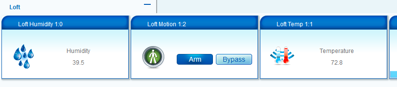
Yes all the sensors came up in the Vera UI, And looks like they work for some minutes
But when i push å button its looks like all things stop working, and after a reboot on the Arduino its working again for a short time and so on -
Yes all the sensors came up in the Vera UI, And looks like they work for some minutes
But when i push å button its looks like all things stop working, and after a reboot on the Arduino its working again for a short time and so onThis post is deleted! -
Yes all the sensors came up in the Vera UI, And looks like they work for some minutes
But when i push å button its looks like all things stop working, and after a reboot on the Arduino its working again for a short time and so on@Hoffan said:
Yes all the sensors came up in the Vera UI, And looks like they work for some minutes
But when i push å button its looks like all things stop working, and after a reboot on the Arduino its working again for a short time and so onTry threading in the sensor reads into each block to read and change its state in one block for each sensor/pin.
I edited you code so it can be read,,, attached.
Remember AutoFormat under Tools in your arduino menu
void loop() { debouncer1.update(); // Get the update value int value = debouncer1.read(); if (value != oldValue1) { gw.sendVariable(BUTTON_PIN1, V_TRIPPED, value==HIGH ? "1" : "0"); oldValue1 = value; } // debouncer2.update(); value = debouncer2.read(); if (value != oldValue2) { gw.sendVariable(BUTTON_PIN2, V_TRIPPED, value==HIGH ? "1" : "0"); oldValue2 = value; } // debouncer3.update(); value = debouncer3.read(); if (value != oldValue3) { gw.sendVariable(BUTTON_PIN3, V_TRIPPED, value==HIGH ? "1" : "0"); oldValue3 = value; } // debouncer4.update(); value = debouncer4.read(); if (value != oldValue4) { gw.sendVariable(BUTTON_PIN4, V_TRIPPED, value==HIGH ? "1" : "0"); oldValue4 = value; } -
So I have created a multi sensor that uses the DHT and motion to get Temp/Hum/Motion. Problem I have though is the update of the hum/temp. I have not been able to figure out a way to get a reliable update on those without blasting the GW/Vera with unneeded announcements (disable sleep function and it keeps updating pretty much every second). So right now the script updates the temp/hum only when motion is seen. I have tried a few things with my limited knowledge of arduino and can't get this to work properly. Can someone please take a look at this sketch and tell me what I am missing? If i change the variables for sleep at the end and try to do an interrupt and a sleep delay, i get an error.
-
Nobody wants to take a crack at this? I figured this to be a common combo and would really like to get it to work properly.
-
Nobody wants to take a crack at this? I figured this to be a common combo and would really like to get it to work properly.
@waynehead99 Here is a sketch I run with DHT and motion support.
#include <Sleep_n0m1.h> #include <SPI.h> #include <EEPROM.h> #include <RF24.h> #include <Sensor.h> #include <DHT.h> #define CHILD_ID_HUM 0 #define CHILD_ID_TEMP 1 #define HUMIDITY_SENSOR_DIGITAL_PIN 4 Sensor gw; DHT dht; Sleep sleep; float lastTemp; float lastHum; boolean lastValue = false; boolean metric = false; #define DIGITAL_INPUT_SENSOR 3 // The digital input you attached your motion sensor. (Only 2 and 3 generates interrupt!) #define INTERRUPT DIGITAL_INPUT_SENSOR-2 // Usually the interrupt = pin -2 (on uno/nano anyway) #define CHILD_ID 2 // Id of the sensor child long previousMillis_T = 0; // will store last time temp data sent unsigned long startTime_T; unsigned long sensorInterval = 30000; // change this to desired sensor read interval in milliseconds void setup() { gw.begin(); // Send the sketch version information to the gateway and Controller gw.sendSketchInfo("Motion Sensor and DHT", "1.0"); dht.setup(HUMIDITY_SENSOR_DIGITAL_PIN); pinMode(DIGITAL_INPUT_SENSOR, INPUT); // sets the motion sensor digital pin as input // Register all sensors to gw (they will be created as child devices) gw.sendSensorPresentation(CHILD_ID, S_MOTION); gw.sendSensorPresentation(CHILD_ID_HUM, S_HUM); gw.sendSensorPresentation(CHILD_ID_TEMP, S_TEMP); metric = gw.isMetricSystem(); startTime_T = millis(); Serial.println("Setup complete"); } void loop() { // Read digital motion value boolean tripped = digitalRead(DIGITAL_INPUT_SENSOR) == HIGH; if (lastValue != tripped) { gw.sendVariable(CHILD_ID, V_TRIPPED, tripped?"1":"0"); // Send tripped value to gw lastValue=tripped; //Serial.println(tripped); } if (millis() - startTime_T >= sensorInterval) { delay(dht.getMinimumSamplingPeriod()); float temperature = dht.getTemperature(); if (isnan(temperature)) { Serial.println("Failed reading temperature from DHT"); } else if (temperature) { lastTemp = temperature; if (!metric) { temperature = dht.toFahrenheit(temperature); } gw.sendVariable(CHILD_ID_TEMP, V_TEMP, temperature, 1); Serial.print("T: "); Serial.println(temperature); } //delay(dht.getMinimumSamplingPeriod()); float humidity = dht.getHumidity(); if (isnan(humidity)) { Serial.println("Failed reading humidity from DHT"); } else if (humidity) { lastHum = humidity; gw.sendVariable(CHILD_ID_HUM, V_HUM, humidity, 1); Serial.print("H: "); Serial.println(humidity); } startTime_T = millis(); } // Power down the radio. Note that the radio will get powered back up // on the next write() call. delay(1000); //delay to allow serial to fully print before sleep } -
Thanks that worked... and for my understanding... looks like your not really using interrupts at all? Looking at the code makes complete sense to me, and proves I was over thinking things on mine.
Thanks again.
-
is it the same process with the new 1.4 library version?
Could you please give us a exemple here or on github to have multiple sensor type on the same arduino with the new 1.4 library?
if it's the same implementation, we could write multiple "gw.present(ID, XXXX);" and send a message for each child ID type?
Thank's very much.

Hello! It looks like you're interested in this conversation, but you don't have an account yet.
Getting fed up of having to scroll through the same posts each visit? When you register for an account, you'll always come back to exactly where you were before, and choose to be notified of new replies (either via email, or push notification). You'll also be able to save bookmarks and upvote posts to show your appreciation to other community members.
With your input, this post could be even better 💗
Register Login