@yoonie said:
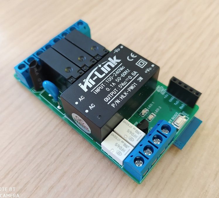
For the pro mini version, should i create another Openhardware project, or should i put it here, in the already existing project?
Might be better to create a new project as they uses a different set of design files.
@gohan - Dell R710 over here, brought pretty cheaply in the UK tbh. I have a few things running on it as I'm Microsoft trained and certified so i enjoy messing with that kind of stuff. I was once in that field and attempted to get some work but nothing ever came from it (i got sick of hearing "Sorry, you don't have sufficient work experience") so I've ended up back in University studying mechatronical engineering Anyway, that is another topic for discussion, you're welcome to message me anytime for a chat, would be nice
Hi @blackchart,
Unfortunately, all devices are sold out. Further production is possible only when ordering more than 10 devices (in this case, I also can modify the device to suit your needs).
@vlad I am having the same issue. Where did you change keepalive timeout to a long time?
Essentially, what file did you edit, what parameter and to how long?
You would use PID if you have a temperature feedback from the rooms, but in your case you are not interested so it doesn't matter much. Sure turning off pump when not needed is a good thing. I have colleague that also bought a few netatmo devices to control floor heating of some zones of his house and he is very happy.