In wall - PCB, (AC to DC 5v)
-
That would be incredibly difficult to do if you're using a metal box purely for the reason of having no room between the brick and the plasterboard (Or whatever finished product you use over where you live).
-
@samuel235 You will probably have to face the radio so it's pointing through the plastic cover (not the metal box) and use repeaters in the rooms where necessary.
-
@petewill I shall give this a test! I'll report back soon, hopefully.
-
Looks great, will you consider to create a version with 2 relays so it will be similar like the Fibaro 2 relay or Qubino 2 relay
I also live in Sweden (Using same wall mechanical dimensions) and are searching exactly for a Mysensor relay 2 device to hide in the wall
-
@bjacobse My thought was to first create one working pcb to start with and leave the upper side for sensors.
This way you can recreate that upper pcb for the needs you have and just add it as a shield to the lower pcb.
-
@sundberg84: hi nice idea

just for curiosity, what does "sweden" box look like??? I live in France, and here the most common style/size is like this: http://www.leroymerlin.fr/v3/p/produits/boite-d-encastrement-legrand-pour-mur-creux-d-67-mm-e29984
is it like yours??
-
This is what I have in my walls and these in the roof in a house in Finland. I bet they are similar in Sweden.
-
thx

it seems you have good quality/strong box not cheap, a little bit bigger than ours. interesting to see difference. so in future, if I will make something inwall for me, it will fit to "nordic" box. cool. unfortunately maybe not the holes...I will check this. but it's not a big problem I think. good to know.
-
Yea. Mine is about d =6,5 mm as well. Reminds of yours.
-
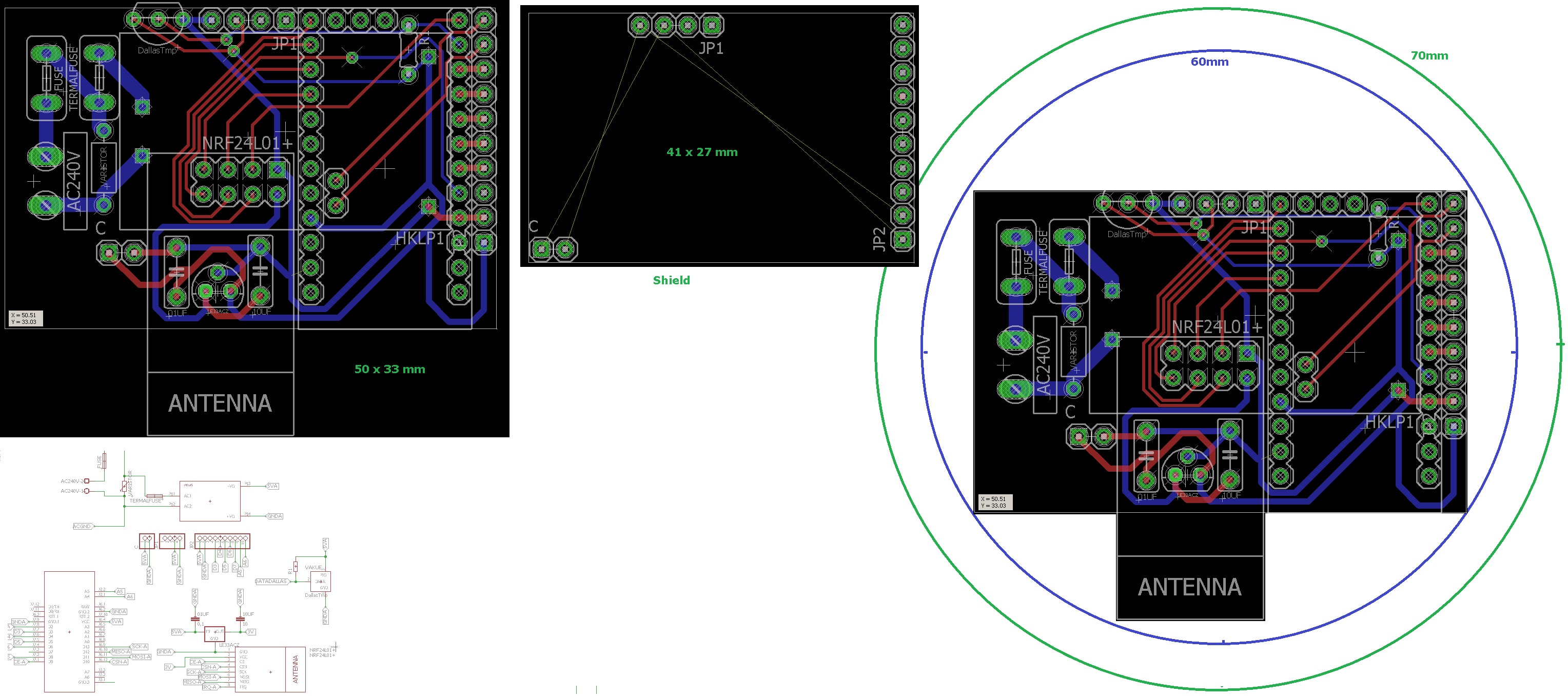
I ended up re-thinking this - and I think this is better.
Now all components are located to 1 pcb, with an empty shield.
This makes it possible to have a standard PCB and just create the shield or make one from a empty board.@m26872 and everyone else - my biggest consern is the distanse between the high power and rest - what do you think? Im no expert.
-
The issue that i personally have at the moment with locating this style of sensor behind a switch is that the slimline boxes in UK have around 15mm of room (depth) inside once the switch itself is fitted. There is slightly more room around the sides but the middle section is around 15mm. I'm now wondering how hard it would be to maybe create a slimmer version or slightly longer, say 70/75mm in length?
-
@samuel235 That is out of my leauge! 10-15mm is pretty much a PCB with the arduino on it. Adding the HLK transformer its like 20-25mm.
Even if i would fit everything on one side the PCB and the HLK transformer should be hard to fit i think.
-
This is where we create stable ones for your socket boxes, then i'll attempt to lay something out in terms of design if possible for a UK version. Lets get a working and stable version of yours going first and we could take it from there i guess.
-
@sundberg84: I'm not expert too, I don't know if it can help you. I hope..
- why not move hilink a little bit on the left...is it what you are talking about? clearance between hilink and nrf? - or about fuse...maybe for fuse...pads could be a little bit smaller. it won't drain too much current so..
if you dont move hilink, maybe increase space between thermal fuse and hilink and the route between them less straight, add a little upper angle, miter/round it a little if you want. but not too near dallastemp of course you know.I guess you want to keep your ac connector middle centered too. - If you want to move hilink, you can maybe change few route like this. there are better ways, sure. I have not looked longtime I hope I don't say dumb things lol, I'm not a pcb expert too. sometimes I can't get the route like I want, and the day after, hop, I see it!

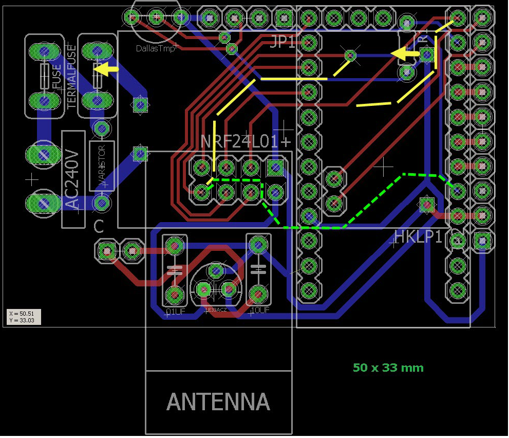
If you have some problems sometimes to get gnd, do you use gnd plane. useful too, but not on ac lol..I think you maybe already know it.
Will you have some holes? how do you plan to fix it inside?
- why not move hilink a little bit on the left...is it what you are talking about? clearance between hilink and nrf? - or about fuse...maybe for fuse...pads could be a little bit smaller. it won't drain too much current so..
-
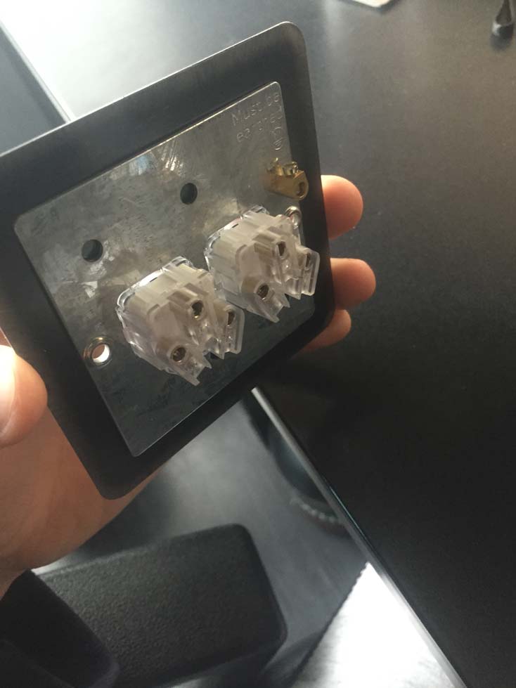
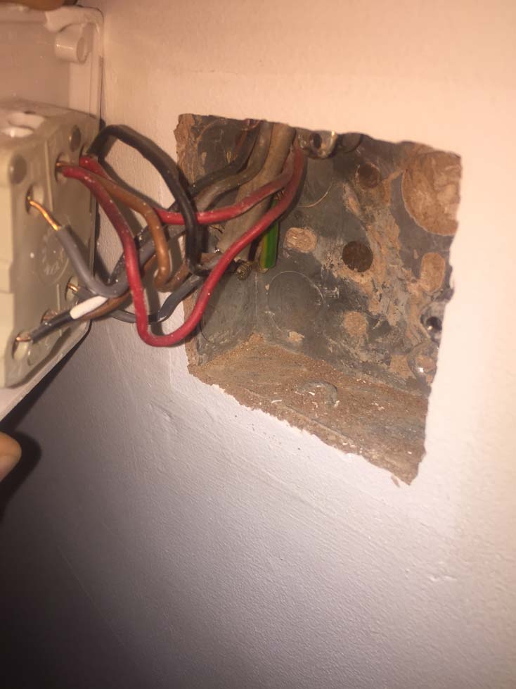
So, this is what i have to contend with. Inside the socket i need to fit an arduino, nano or mini and some form of power supply (cell battery looks the only way) an nRF24L01 and then connect it to the rear of the switch. I may have to create my own board and arduino to reduce the footprint of my design to enable it to fit. Idealy i want to keep those current wires in the box but terminated, simply so if we move house all we need to do would be to remove the terminals and rewire into the switch.
-
I've been thinking about installing a PCB with transformer in the wall myself. I like this project, but how do you feel about leaving exposed high voltage circuitry in the wall box. Normally the wires in the box should have at least one layer of insulation and splicing should be done inside insulated caps. Don't know all the correct terms in English, so I hope you understand what I mean.
Ideally I'd want a box for the PCB inside the wall box, but that will probably never fit. Right now my plan is to put a new box on the outside of the wall next to the coupling box up under the ceiling vertically ~ 120 cm from the wall box with the buttons for the lamps etc. But in my basement there are no coupling boxes under the ceiling, so there I'm forced to put everything inside the wall box, if I want it to look good.
Any other ideas?
-
@martinhjelmare In your case it would be high voltage open circuitry as you plan on running it on the existing power lines that are there currently. If i understand what you're saying anyway, am i correct? However, in my case, i plan on terminating the existing wires in a terminal block or taping them off if possible to save space, then have my sensor node running off of a custom PCB holding a custom made Arduino to save even more space and then run the whole board off of a cell coin battery.
-
My worry, when having exposed high voltage circuitry inside a standard wall box, with otherwise insulated wires, is that someone else than me, for example an electrician, might poke around unknowingly in the box and get electrocuted. If you have the PCB inside a separate box with warning label, the risk is at least slightly lower.
-
@martinhjelmare I would agree, with your situation, and like that proposed on this PCB design (@sundberg84, please correct me if i'm wrong), like i said in my previous post. You should either conceal them or avoid using them. That is what i would advise (using UK/British rules and regulations).
-
Maybe someone could open a own thread discussing this with a battery operated in wall node.
For example, someone needs to put a circiut diagram for how to operera that relay with power only from the battery.
-
I agree with @martinhjelmare I just assumed there would be some other insulation and it would be the second step of the design. Good you cleared this out early.
I think it is almost possible, but really hard, to copy the size and shape of commercial in-wall devices and still fit in all we want. Small customized PSUs may be necessary.
Personally I'd prefer external boxes. They could be in wall as well, as long as there's space for safe (diy) designs or even future projects.
-
I'm thinking I'd like to try and design a custom box for 3d printing that could fit this project by @sundberg84 and also fit inside the wall box. Has this been done already and do you think it's worthwhile, i.e. is it possible?
-
What I know of, this has not been done before... not the PCB or the 3d printing.
Good points taken above! We need to consider this and this might not be the optimal design.
Maybe thought was that this design can break some ground and maybe it can lead to better and even smaller designs.I like my designs easy
 Pro Minis with ready bootloaders so everyone can be inluded, but this might not be possible...
I will still finish my design and see how it looks.
-
Hey everyone. Been following this as I'm very interested in having this functionality with the Arduino's. I'm a newbie and have very limited knowledge with anything electrical, so forgive my ignorance. How is this problem any different than what the X10/ZWave/etc. solutions have already overcome years ago? I have an X10 wall socket that does very similar switching on/off of one socket. All the components are built inside the socket, putting the control components and the high voltage very close together. The wall switches are another example. They always have some current running thru them even when the light is switched off, to detect the signal. Again, forgive my lack of understanding how all this works, but it seems like this may not be as big of an issue as I'm reading here. Thanks.
-
Some awesome input here for @sundberg84's project! I would love to see your designs completed whether or not they suit other people's situations dude. Once you have completed yours then we can build from your base to create another product that would suit others. Note i said build ANOTHER product, not upgrade yours. Your's would be widely used by others, just not the ones that need it inside of a UK Sized box maybe. So, most importantly, lets help develop yours and help test it if needed.
I'm going to be doing some basic designs on getting a battery powered one installed into a UK socket as my next major development in my network, so we might have a starting point by the time yours is nearing completion.
If you need any input/help/testing just give us a shout

-
I started a new thread for my attempt at a custom box design.
http://forum.mysensors.org/topic/2509/box-for-in-wall-pcb
-
I have also started my own thread to save me clogging your development thread up @sundberg84. I'm hoping that we can gather seperate ideas and then discuss to develop products that are a creation of many of opinions/improvements.
-
I recieved my PCB today - Yea!
The good news is - its working, and it fits inside my wall socket.
The bad news is that as always i will need another revision - the hole for the fuses are to close to each other.Some pictures:
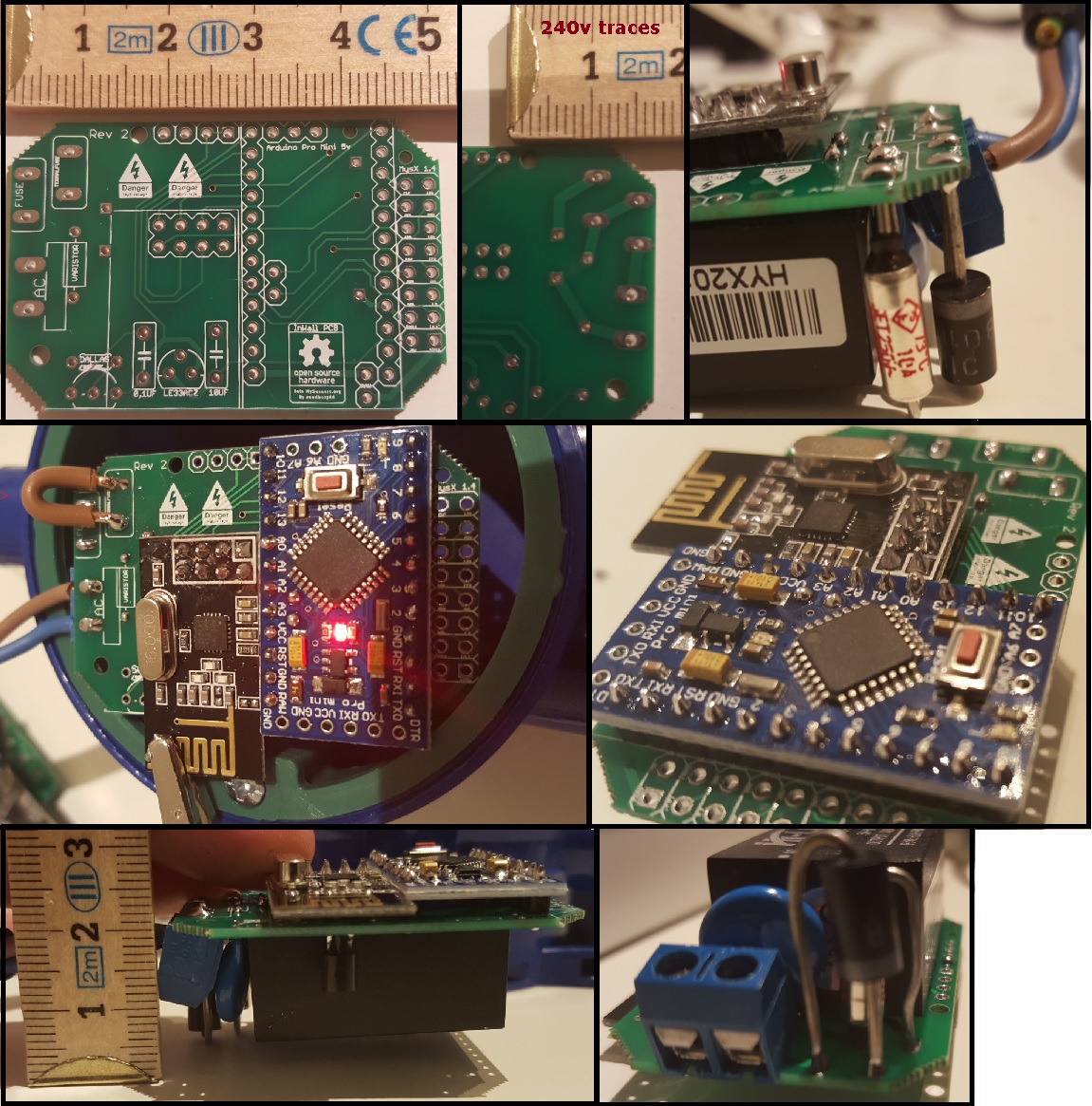
Anyone with any input on this?
-
@sundberg84 Fantastic news on receiving this before the Christmas dull in mailing! Super happy for you to receive, populate and get working your custom board dude! I have no input other than to congratulate you on a successful board, shame on the fuse issue
 Could i ask you, do you have any components sitting under your nRF module?
I'm currently having a few little teething issues on getting the board down in size slightly, it should fit my application as it is right now, but i would like it a little smaller. The thing that is really holding me back on sizing is the screw terminal being a 4 pos block. I might have to reset to maybe 2 x two pos, or even some singles. Although i only need two switches on this particular application, i would like to make it accept 3 so just in case i install a 3 way switch somewhere, i am able to use this board, rather than creating another.
Hopefully I'm not too far away from completion now.
-
Nice! Good images, and thanks for the scale. Is your wall box also 4 cm deep, like the ones I have in my house?
-
Hi all,
It looks very good @sundberg84, It's still a little bit bigger than fibaro switch but costs much much less Looking forward to see your next revision
Is it any chance to place another screw terminal to allow turn on/off not only via radio but with the local button as well?
From other side as a workaround it still should be possible to hard soldering some wires to appropriate pin on arduino side.I'm wondering why some Asia manufacturer is not able to build a tiny pcb with integrated arduino, nrf radio, ac-dc trafo and relay on one single board to keep small footprint.
-
@sundberg84 Good job and nice fit! Looks like you can even make the discussed separate box-in-box for it if you like.
Do you have a BOM of the parts you used this far? And which ones you need to replace or move around.
-
@samuel235 - No components between the NRF and the PCB but yes, if you mean on the other side of the pcb. There is the 5->3.3v converter and caps.
@martinhjelmare - Yes, 4.5cm it seems but there is some room on the sides so i hope to be able to squise in a relay.
@łukasz-rybak - You can connect a local button between d3 and gnd on the MYSX connector on the right side. This can read the switch and change a relay depending on what state the switch is in.
@m26872 - Yea, lets hope so... ill do another revision of the board and lets see where this ends up.
-
So, my rev 3 is coming along:
- moved the Dallas temp sensor
- added some more space for the 240v fuses:
- labels changed
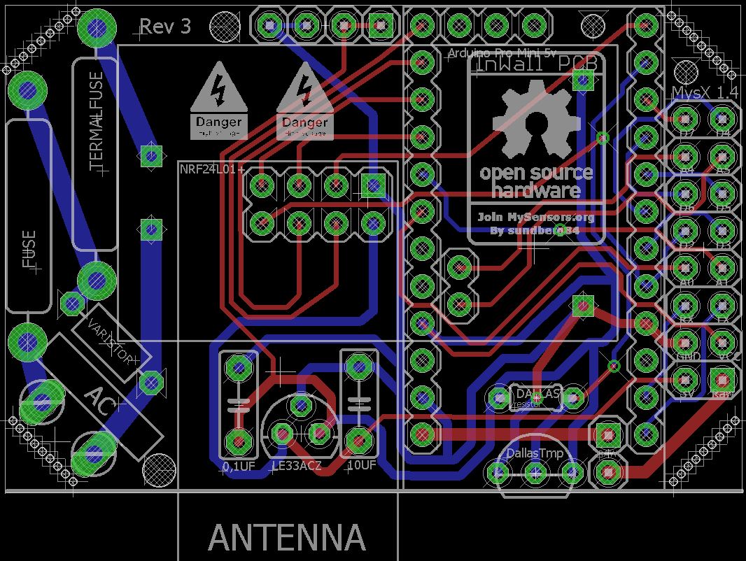
The BOM? Is that the parts used?
I have used what we concluded here:
http://forum.mysensors.org/topic/1607/safe-in-wall-ac-to-dc-transformersThis is what i bought (no garantees given this works/doesnt burn)
HKL-PM01 http://www.ebay.com/sch/sis.html?_nkw=HLK-PM01+AC-DC+220V+to+5V+Step-Down+Power+Supply+Module+Household+Switch+Q15274&_id=351418782712&&_trksid=p2057872.m2749.l2658
(DO NOT BUY THIS!!)Fuse http://www.ebay.com/itm/111433875797?_trksid=p2057872.m2749.l2649&ssPageName=STRK%3AMEBIDX%3AIT
Thermal Fuse http://www.ebay.com/itm/221560426284?_trksid=p2057872.m2749.l2649&ssPageName=STRK%3AMEBIDX%3AIT
Varistor http://www.ebay.com/itm/260848704608?_trksid=p2057872.m2749.l2649&ssPageName=STRK%3AMEBIDX%3AITPro Mini 5v
Nrf radio
LE33a http://www.ebay.com/itm/400691492273?_trksid=p2057872.m2749.l2649&ssPageName=STRK%3AMEBIDX%3AIT
-
@sundberg84 said:
@samuel235 - No components between the NRF and the PCB but yes, if you mean on the other side of the pcb. There is the 5->3.3v converter and caps.
Just to let you know, I meant in between the nRF board and the PCB, so thank you for letting me know

Rev 3 is looking pretty neat and tidy if i must say so. Keep up the awesome design work, I'm learning off of you, thank you!

-
@sundberg84 Yes, the BOM is the list of all components that populates your PCB. References, values, source and all other specifications that the "manufacturer" will need.
I was actually mostly interested in the fuse looking like a big diode in your picture. Is it ordered from that link you showed? Which value is it?
-
@m26872 Its the slow blow fuse, and I ordered 240v, dont remember which current and that is offcourse whats interesting. On a business trip but can check this weekend when i get home. The datasheet for the HLK refers to:
Maximum input current ≤0.2 A
Input current surge ; ≤10 A
-
Maybe you should add a ground plane on the low voltage part of your design on both sides, but avoid the area where the NRF24L01+ antenna is placed
-
@sundberg84 Could I ask where you order your boards from, which manufacturer do you use and would you recommend them?
-
I order from itead. Works great and good quality.
-
@sundberg84 The closest fuse-alike I've found in a DO-204 (semiconductor-) package, is the TVS diode. Typical breakdown voltage seems to usually be a lot lower than 230V, so I guess you should apply a low voltage (<10V) if you want to test if it conducts. Fuse break current is the most interesting test of course.
-
@sundberg84 They look like they provide a pretty stable and awesome service. What sort of turn around did you get from ordering to receiving the PCB?
-
@mzuidwijk : The HLK library for eagles: HKLPM01.rar
@m26872 : Since the ciriut works it conducts, i have not tested at which point it breaks because i dont have that equipment would be great if we somehow could estabilsh the right compont to use.
-
@sundberg84 Of course it conducts, probably bidirectional too since it works well for you. That's why I suggested a TVS diode. The test was meant as an easy way to find more info even if it does not fully rule out that it still could be something else than a normal fuse. I'm sure you have possibility to test if something conducts or not at low voltages. If it does not, it is not a fuse. Use a new component since it could be a "fail-short" type one.
Then if you connect it in series to a load (> 230V*0.2A "=" 46W), it should blow if it's a fuse.That first fuse is the no1 safety component and should be trusted. I would never just rely an some 10A house fuse to a diy design like this. Removing the varistor could limit the failure modes in the meantime.
-
@m26872 Ok, you seem to know more about this - i have pretty much tried to sum up what was told in the safe-in-wall thread.
Do you agree with that thread or would you do it some other way ? (High power parts and HKL PM01).
-
@sundberg84 I think the conclusions of that thread is just fine. Now here, it's just a matter of a single component. If you feel safe as it is, ok by me.
I've done quite a few diy's over the years and that fuse has been my insurance. And saved me, more than once...
Edit: That last sentence sounded a bit bumptious, sorry. I now understand that you probably meant what I said about removing the varistor. There I meant that the varistor is after the fuse because of its hazards. If there is no fuse, it could be better to remove the varistor or at least place it after the thermal fuse.
-
@m26872 I really appreiacte your posts! I never feel safe enough! Would it be safer to have the varistor after the thermal fuse as well? Then the thermal fuse breaks both if the varistor gets hot from over voltage and also protect the HLK.
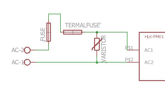
I will try to test my fuses as well - its a good thought. - You never know what you get from Ebay!
Edit: The "fuse" conducts low voltages (1.3V) connected to a normal battery and my Multimeter - so this excludes that it is a TVS diode?
Will later find some eqipment drawing more than 45W and see if that blows it Love to blow stuff...
-
@sundberg84 Yes, that fuses-varistor arrangement is like how I do it.
Great that it conducts, I hope in both directions or else it's a diode.
-
@m26872 It conducts both ways, and there is some voltage depending resistance because the volage drops and its different depending which way i put gnd.
Also, it does not blow
 so its not a fuse.
At the end i connected my vaccumcleaner (1000w) and it didnt blow, all it did was vaccum really slow so i guess its some sort of bidirectional TVS. Good find, thank you!I will keep looking for a 250v 200mA fuse (small) one - you dont happen to know one?
-
Also, i tested the thermal fuse and that one killed/blew! Couldnt measure the exakt temp because all i had was my barbecue thermometer atm and i fired to much to fast... but it blew pretty much were it was supposed to.,
-
@sundberg84 said:
@m26872 It conducts both ways, and there is some voltage depending resistance because the volage drops and its different depending which way i put gnd.
Maybe a zener diode? Can you read some figures on it?
Also, it does not blow
 so its not a fuse.
 Good job with the testing!
You're welcome.
I will keep looking for a 250v 200mA fuse (small) one - you dont happen to know one?
This far I've only used standard replacable 5x20mm glass fuses and holders (preferably covered). These are safe and proven but quite bulky and hence not as convienient for our PCB designs. I've ordered a few small ones with solderlegs for testing but not yet recieved them.
-
New revision ordered:
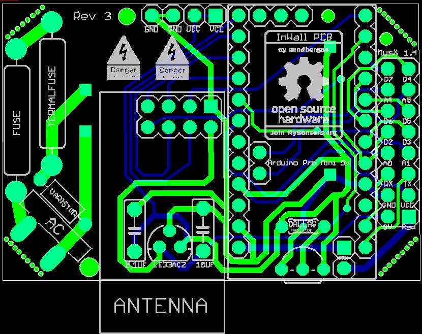
and also some new fuses:
http://www.ebay.com/itm/290767404446?_trksid=p2057872.m2749.l2649&ssPageName=STRK%3AMEBIDX%3AIT
http://www.ebay.com/itm/231765976267?_trksid=p2057872.m2749.l2649&ssPageName=STRK%3AMEBIDX%3AITOf of them is 500mA but that cant matter that much?
Spec of HKL:
Maximum input current ≤0.2 A
Input current surge ; ≤10 A
-
@sundberg84 Would you mind posting pictures of your fuses that turned out not to be fuses? I think a few of us ordered from the same store and I'd like to update my original post with a warning. Also, if you don't mind can you post a step by step way for to easily test? If there is another way besides connecting to my vacuum cleaner that would be awesome

@m26872 & @sundberg84 can you describe in a little more detail the change of placement of the Varistor? I don't really understand why it's better to change the placement. I'd like to update my first post in this thread with the best/safest method http://forum.mysensors.org/topic/1607/safe-in-wall-ac-to-dc-transformers
Thanks!
-
@petewill The varistor itself is a risk. The moved thermal fuse will then also work as a redundant and diversified protection (to the main fuse) of the varistor and still protect the load as before.
-
I now have my boards in transit on their way to me as we speak @sundberg84, the next revision will see some development towards some AC/DC conversion i think. However i have a lot of work to do, a lot of learning electronics before i go anywhere near to installing a AC/DC converted board into my wall. Safety first and all that jazz! I love the look of your board layout with the arduino being a add-on board essentially. So as soon as i have my battery version up, working and dialed in for performance, i will be using your board as a learning curve for some AC/DC powering. I actually have printed the above picture of your board out and i'm creating a schematic of it, using it to learn the steps you have taken to get your power to the arduino. I love the fact you have added a temp sensor in there, i'm not too sure why you did that (your personal requirements) but i would love to use this as another trip out sensor to cut the board's power if it detects it getting too hot inside of the socket.
By creating my own i'm not trying to better or improve yours, its simply because for mine to work i would like it to be acceptable into a 29mm depth back box (29mm is with the switch back too, its pretty cramped inside these).
Lastly, is there any chance you could point me in the direction to a copy of your logo/design on the board (The open source, join MySensors.org) so i could include it into mine. I would also like to have the MySensors' official logo on my finished board too, do you know if there is any links/pages/repos to this data or would i just need to create my own as a BMP or Library device?
-
The test I did was just to strip a extension cord, attach "the fuse" to it and apply different equipment with spec from 5W up to my vaccumcl 1000+W Not proffessional but I dont have any other equipment.
I dont think we changed the placement? I made a misstake in my first rev but now my varistor placement is like your post (after both fuse and termal fuse). But @m26872 link describes it good why.
@samuel235 Good luck with your board! Do not take my board as "thats how it should be". My board is the result and my interpretation of the discussions so far in this forum. If that is right or wrong i not able to tell (yet). The tempsensor is to initially be able to measure the temp in that closed box to see that the node doesnt produce to much heat.
Im glad you are creating your own... as i said before, my wish is that we all come together and in the end create a small and safe in wall PCB. And If you want (and use Eagles) ill send over the files for the PCB. I will also post them here when i recieved the boards offcourse.
Here is my bitmap I use as a logo... in eagles you can import that to layer 21 and apply to your board.

-
Awesome, yes if you could send me the eagle files I would really appreciate that to allow me to learn how this circuit is working. I completely understand that this is just your interpritation on how it should work. I'm using this as a kind of reference i suppose, just to learn how this is wired out, whats connected in what order etc etc. I will not take this as a 'only way to get ac power to arduino on one board' type of application, don't worry

Thank you for the BMP Image, i will add the MySensors logo to the board too along side of this logo.
The parts for my board have just arrived as I was replying to this. Just waiting on the boards to come from ITead now. Time to get moving!
I have a weird feeling that 2016 will be huge for MySensors and its community!
-
@sundberg84 Thanks for the picture. It's totally different than mine. You said you got it from the same store I linked to in the "Safe in-wall" post? This is what mine looks like:
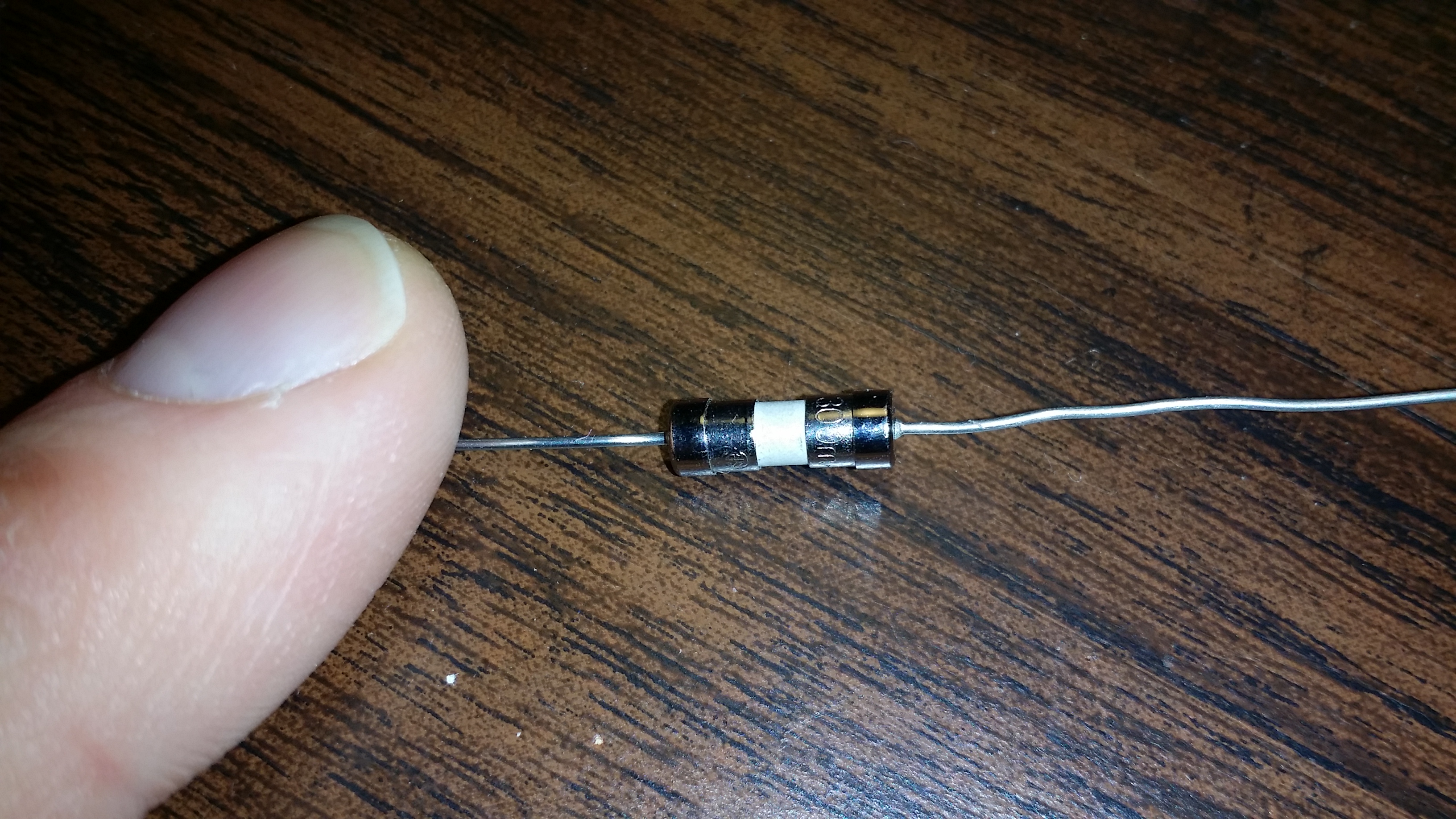
I will still test it with to be sure but I'm reassured that it at least looks different.
I dont think we changed the placement?
Sorry, you're right, my mistake. I misread/misunderstood the issue as I was reading through this thread. It was still helpful to read @m26872's link though, thanks for that!
-
@sundberg84 Your 'fuse' looks very much like a regular diode, e.g. 1N4007:
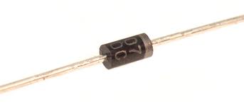
You can easily verify by using a multimeter, or even the printing on the component could reveal its real identity.
Some sellers ship both clothes and electronic components, so maybe the seller just shipped the wrong parts?
-
@Yveaux Yea, could be - its not a 1n4007 because i have those as well, and also it conducts in two ways. Anyway, you are probably right - they shipped the wrong item. @petewill I ordered from the link in safe-in-wall thread: http://www.ebay.com/itm/111433875797?_trksid=p2057872.m2749.l2649&ssPageName=STRK%3AMEBIDX%3AIT&rmvSB=true
-
I finally had a spare minute to test my fuse. Good news, it worked! I plugged in a 13 watt florescent light bulb and it turned on. I then plugged in a 32 Watt florescent light bulb and it blew the fuse. @sundberg84 sorry you got the wrong ones! Hopefully other people who ordered got the ones that I did.
-
@sundberg84, gr8 job done....really amazing to see this one. i want to make few sensors for my home. Is the design of the board is final? Kindly guide me for the placement of LE33 and Dallas Temp as mentioned in your BOM that placement "solder Le33 + Caps (1,0, 10uf) on the pcb underside. Note the directions of the LE33 (not as silk mask!)"
Also, will it be possible for you to upload the design to http://dirtypcbs.com, as i don't have any knowledge about PCB manufacturing. it will be very easy for me to order and get the PCBs for assembly.
I am very new to all this and learning from you guys.....
Thanks
Brijesh
-
@Brijesh-Mishra Thank you! Im waiting for Rev3 to arrive. It was manufactured a week ago so i guess it will arrive on 1-2 weeks. I will post and let you know the status here.
I will also update the BOM with better instructions. LE33 should be soldered on the back side which reverse the direction of the pins (VCC/OUT). This means that the nice print on silkmask (white markings how the LE33 should be mounted) is not correct.
Its a nice idea at dirtypcb, I can do that i guess!
-
Rev 3 arrived today and its working, nice.
I soldered it togheter and uploaded a dallas temp sketch and ran it with AC power.Next step is a long time test in a small space, measuring temp.
Also it would be nice to get some tips how i can test it more... (safety check).Files and readme can be found in the first post.
Also this image for where i assemble the pcb (build).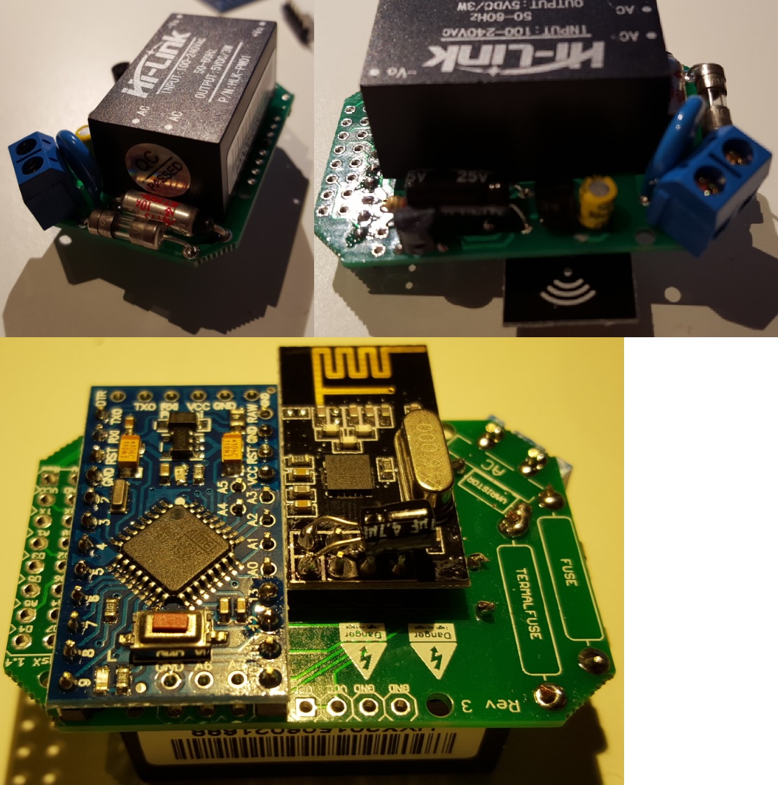
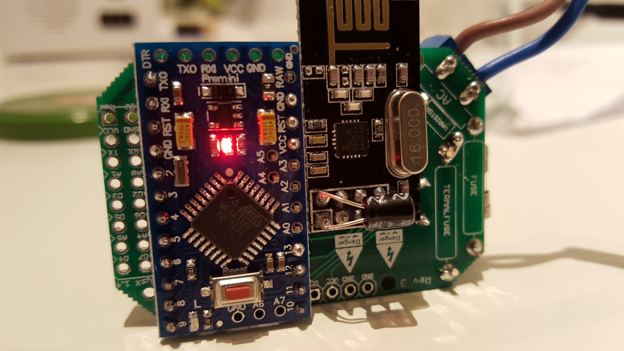
-
@sundberg84 This is awesome progress dude!
So in my honest opinion, from a professional tradesman plastering, tiling, stud walls, plaster boarding are my specialties, I would firstly test this inside of a back-box, outside of a wall with the front attached (like it would be in a real-life situation). Then once that passes your expectations and requirements, I would then test it inside of a back-box located inside of a wall but without the front plate screwed on. Then once that passes, I would connect the front plate and manually monitor the temps inside of the controller.
If your question was aimed more towards how to test it electronically, then i'm sorry i can't help in that department, as you already know, I'm pretty weak at electronics at the moment still.
Its awesome to see your project coming on, very swiftly too. Keep up the good work!
-
@sundberg84 - Correct me If i'm being a complete NOOB here....
Your fuses, if they are the same function as what i feel to be a 'general household fuse', could you not use a removable fuse in a holder. This way if a fuse blows/trips all you would need to do is change out the fuse. This is all depending on what caused the fuse to blow, if it was an environment issue (spike of power draw, etc) then you could just change the fuse and power back up... Rather than having to get the soldering iron out.
Again, If I have incorrectly understood the principle of the fuse in this application, please notify me.
-
@samuel235 You are right - the only problem is size.
If you find a removable fuse as small as this axial fuse please let me know!
Most are 2x20mm and the holder are bigger.
-
So today I have been testing temperatures inside a closed compartment with my PCB.
I drilled a hole in a metal cap to a glass bottle, put AC main through the metal cap and wrapped everything up inside. I then found some insulation material and wrapped the glas bottle up.- First test was only minimum components and sleep for two minutes.
- Second test was the same but i added a LCD screen on maximum background lights and also a relay which switched on and off every 2 minutes sleep cycle.
- Third test was to remove the sleep and used wait instead so the node was powered all the time.
No problems so far, max temp during last test was 34,8 dgr C. Here is my numbers:

Any other ideas or components i can use to try - write a post!
-- Next
So... there are some (important) questions ahead i dont know how to answer though...
- Reliability, when will it fail? (compared to a commersial product?)
- How will it fail? What is it weakest point?
- Will my safety components be enough and prevail damage... ?
- What will happen when it fails?
Anyone having thoughts... let me know.
-
@sundberg84 said:
@samuel235 You are right - the only problem is size.
Ahh okay, indeed you're right. However, what is going on the front of the in wall box? Is it still being mounted inside of a wall box, or are you have it concealed away behind the wall where you can't really get to it easily? It isn't behind a light switch/socket?
-
@samuel235 depend on what you wants to do with it - its dynamic since you have the pins. If you want to add a relay and button you can hide it in the wallbox and still have the physical button or in the ceiling if you dont need that.
-
@sundberg84 - So It Is essentially a 'multi-use backboard' kind of application. So what I was trying to get to - In the UK we have something called a fused switch (link to image below). Now, you see that little rectangle to the side of the switch, its a fuse inside of a holder. I'm wondering if a possible model for a switch plate like that or any front plate to suit the needs (screen, switch, motion sensor, etc) could be maybe 3d printed, with that fuse holder incorporated into the front late with the board that you have made attached to the back of the front plate in such a manor that you can swap the fuse out without dismantling the whole socket or even soldering. Just a suggestion, well a huge suggestion at that i suppose.
-
Im getting quite bad radio performance when i seal this inside some boxes... works much better if I dont have the lid on.
Does anyone know if the HLK can interfere with the radio (magnetic fields or anything)? EMF?
Power supply to radio has both 0.1 and 10 caps so I dont hope its spikes or power to radio thats bad.Maybe I should move the radio away from AC side?
-
@sundberg84 Connect a battery supply instead of the LE33 and see if it helps?
-
@m26872 Yea, could try that one - nice thinking.
Made a testnode to see some performance on my PCB.
Combined temp, hum (DHT), motion and light sensor.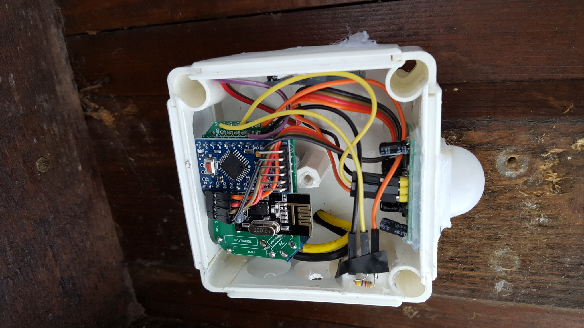
Sometimes i forget to think before i build though... not smart to measure temp and put it besides a power supply that generates heat, doh!
-
Trying to take this to the next level:
3d design - first try (ever!).
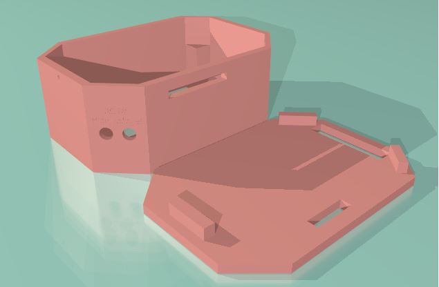
I guess it wont meet any standard since its not completley sealed up - but I want to be able to reach the MYSX connector. Might be OK if I use a female pin header to MysX connector, then it wont be possible to put your finger inside.
-
So, just a small update - im waiting for new PCB and parts (going to SMD components), almost everything has arrived but some nessecary things still missing.
I will leave this project here but not develop this version any more.
Instead I will create a new thread with the new SMD version!
-
Hi all. I have been searching for a way to power nodes and stumbled across this project. My question is is this a viable and safe solution if I just recreate the ac-dc portion on perf board? In essence I want to create a good 5v power supply that can be hardwired into my home inside of an electrical box. Not necessarily in the wall but in less accessible places like attics and such.
-
@Ddawme - Hi!
I suggest you read all the links in the project for example:http://forum.mysensors.org/topic/1607/safe-in-wall-ac-to-dc-transformers
https://forum.mysensors.org/topic/4175/clearance-creepage-and-other-safety-aspects-in-mysensors-pcbs
