SI7021 Multisensor - first try
-
Here's my interpretation of sensbender's si7021 implementation (thx @tbowmo). Maybe you can get some inspiration.
/* Sketch with Si7021 and battery monitoring. by m26872, 20151109 */ #include <MySensor.h> #include <Wire.h> #include <SI7021.h> #include <SPI.h> #include <RunningAverage.h> //#define DEBUG #ifdef DEBUG #define DEBUG_SERIAL(x) Serial.begin(x) #define DEBUG_PRINT(x) Serial.print(x) #define DEBUG_PRINTLN(x) Serial.println(x) #else #define DEBUG_SERIAL(x) #define DEBUG_PRINT(x) #define DEBUG_PRINTLN(x) #endif #define NODE_ID 131 // <<<<<<<<<<<<<<<<<<<<<<<<<<< Enter Node_ID #define CHILD_ID_TEMP 0 #define CHILD_ID_HUM 1 // #define SLEEP_TIME 15000 // 15s for DEBUG #define SLEEP_TIME 300000 // 5 min #define FORCE_TRANSMIT_CYCLE 36 // 5min*12=1/hour, 5min*36=1/3hour #define BATTERY_REPORT_CYCLE 2880 // Once per 5min => 12*24*7 = 2016 (one report/week) #define VMIN 1900 #define VMAX 3300 #define HUMI_TRANSMIT_THRESHOLD 3.0 // THRESHOLD tells how much the value should have changed since last time it was transmitted. #define TEMP_TRANSMIT_THRESHOLD 0.5 #define AVERAGES 2 int batteryReportCounter = BATTERY_REPORT_CYCLE - 1; // to make it report the first time. int measureCount = 0; float lastTemperature = -100; int lastHumidity = -100; RunningAverage raHum(AVERAGES); SI7021 humiditySensor; MySensor gw; MyMessage msgTemp(CHILD_ID_TEMP,V_TEMP); // Initialize temperature message MyMessage msgHum(CHILD_ID_HUM,V_HUM); void setup() { DEBUG_SERIAL(115200); DEBUG_PRINTLN("Serial started"); DEBUG_PRINT("Voltage: "); DEBUG_PRINT(readVcc()); DEBUG_PRINTLN(" mV"); /* delay(500); DEBUG_PRINT("Internal temp: "); DEBUG_PRINT(GetInternalTemp()); // Probably not calibrated. Just to print something. DEBUG_PRINTLN(" *C"); */ delay(500); // Allow time for radio if power useed as reset gw.begin(NULL,NODE_ID); gw.sendSketchInfo("EgTmpHumBat5min", "1.0 151106"); gw.present(CHILD_ID_TEMP, S_TEMP); // Present sensor to controller gw.present(CHILD_ID_HUM, S_HUM); DEBUG_PRINT("Node and "); DEBUG_PRINTLN("2 children presented."); raHum.clear(); } void loop() { measureCount ++; batteryReportCounter ++; bool forceTransmit = false; if (measureCount > FORCE_TRANSMIT_CYCLE) { forceTransmit = true; } sendTempHumidityMeasurements(forceTransmit); /* // Read and print internal temp float temperature0 = static_cast<float>(static_cast<int>((GetInternalTemp()+0.5) * 10.)) / 10.; DEBUG_PRINT("Internal Temp: "); DEBUG_PRINT(temperature0); DEBUG_PRINTLN(" *C"); */ // Check battery if (batteryReportCounter >= BATTERY_REPORT_CYCLE) { long batteryVolt = readVcc(); DEBUG_PRINT("Battery voltage: "); DEBUG_PRINT(batteryVolt); DEBUG_PRINTLN(" mV"); uint8_t batteryPcnt = constrain(map(batteryVolt,VMIN,VMAX,0,100),0,255); DEBUG_PRINT("Battery percent: "); DEBUG_PRINT(batteryPcnt); DEBUG_PRINTLN(" %"); gw.sendBatteryLevel(batteryPcnt); batteryReportCounter = 0; } gw.sleep(SLEEP_TIME); } // function for reading Vcc by reading 1.1V reference against AVcc. Based from http://provideyourown.com/2012/secret-arduino-voltmeter-measure-battery-voltage/ // To calibrate reading replace 1125300L with scale_constant = internal1.1Ref * 1023 * 1000, where internal1.1Ref = 1.1 * Vcc1 (per voltmeter) / Vcc2 (per readVcc() function) long readVcc() { // set the reference to Vcc and the measurement to the internal 1.1V reference ADMUX = _BV(REFS0) | _BV(MUX3) | _BV(MUX2) | _BV(MUX1); delay(2); // Wait for Vref to settle ADCSRA |= _BV(ADSC); // Start conversion while (bit_is_set(ADCSRA,ADSC)); // measuring uint8_t low = ADCL; // must read ADCL first - it then locks ADCH uint8_t high = ADCH; // unlocks both long result = (high<<8) | low; result = 1125300L / result; // Calculate Vcc (in mV); 1125300 = 1.1*1023*1000 return result; // Vcc in millivolts } // function for reading internal temp. From http://playground.arduino.cc/Main/InternalTemperatureSensor double GetInternalTemp(void) { // (Both double and float are 4 byte in most arduino implementation) unsigned int wADC; double t; // The internal temperature has to be used with the internal reference of 1.1V. Channel 8 can not be selected with the analogRead function yet. ADMUX = (_BV(REFS1) | _BV(REFS0) | _BV(MUX3)); // Set the internal reference and mux. ADCSRA |= _BV(ADEN); // enable the ADC delay(20); // wait for voltages to become stable. ADCSRA |= _BV(ADSC); // Start the ADC while (bit_is_set(ADCSRA,ADSC)); // Detect end-of-conversion wADC = ADCW; // Reading register "ADCW" takes care of how to read ADCL and ADCH. t = (wADC - 88.0 ) / 1.0; // The default offset is 324.31. return (t); // The returned temperature in degrees Celcius. } /********************************************* * * Sends temperature and humidity from Si7021 sensor * Parameters * - force : Forces transmission of a value (even if it's the same as previous measurement) *********************************************/ void sendTempHumidityMeasurements(bool force) { bool tx = force; si7021_env data = humiditySensor.getHumidityAndTemperature(); float temperature = data.celsiusHundredths / 100.0; DEBUG_PRINT("T: ");DEBUG_PRINTLN(temperature); float diffTemp = abs(lastTemperature - temperature); DEBUG_PRINT(F("TempDiff :"));DEBUG_PRINTLN(diffTemp); if (diffTemp > TEMP_TRANSMIT_THRESHOLD || tx) { gw.send(msgTemp.set(temperature,1)); lastTemperature = temperature; measureCount = 0; DEBUG_PRINTLN("T sent!"); } int humidity = data.humidityPercent; DEBUG_PRINT("H: ");DEBUG_PRINTLN(humidity); raHum.addValue(humidity); humidity = raHum.getAverage(); // MA sample imply reasonable fast sample frequency float diffHum = abs(lastHumidity - humidity); DEBUG_PRINT(F("HumDiff :"));DEBUG_PRINTLN(diffHum); if (diffHum > HUMI_TRANSMIT_THRESHOLD || tx) { gw.send(msgHum.set(humidity)); lastHumidity = humidity; measureCount = 0; DEBUG_PRINTLN("H sent!"); } } -
Big THX,
now i have understand how to use the si7021 :)
Reading works great!
But the sleeping current is very high ~1500uA
@n3ro said:
But the sleeping current is very high ~1500uA
Mine sleeps at 11uA.
#define DEBUG is a very cool idea!!!
I think I stole it from @BulldogLowell. Credit to him if so.
i get a serial output if DEBUG is not definded
You also have the "define DEBUG" in the mysensors config-file. Is it that serial output you're referring to?
-
Sorry didn't come around to answer you, but it seems that others picked up on my hint :)
Have you uncommented #define DEBUG line in MyConfig.h? If not, then that's why there is still debug..
-
Speaking of the Si021, has anyone tried to use 2 Si7021 sensors on the same node?
-
It's the way that the libraries are build.. They don't care about how your defines are in your sketch (unless you are on dev branch of the mysensors library.. We are bending arduino build system in that one)
Si7021 has a fixed i2c bus address, so only one can exists on each i2c bus. You could of course use bitbanging to create a second one. But why do you want to have multiple Si7021 on one node?
@tbowmo said:
But why do you want to have multiple Si7021 on one node?
I was going to use a sensbender node in a location where I would have needed to use an external sensor and instead of attempting to remove the Si7021 from the sensbender I would have just added another (external) one if it was possible. Is there any other temperature sensor that is as good as the Si7021 in battery applications that I could use instead?
-
Big THX,
now i have understand how to use the si7021 :)
Reading works great!
But the sleeping current is very high ~1500uA
@n3ro said:
Big THX,
now i have understand how to use the si7021 :)
Reading works great!
But the sleeping current is very high ~1500uA
If you got this breakout: http://www.aliexpress.com/item/Industrial-High-Precision-Si7021-Humidity-Sensor-with-I2C-Interface-for-Arduino/32340228487.html?ws_ab_test=searchweb201556_1_79_78_77_80,searchweb201644_5,searchweb201560_1 it includes a 3.3v regulator and level shifting so you can actually use the sensor with a 5v arduino but it consumes quite a bit of current (60uA in the ones I got) even when idling.
What I did was desolder the regulator and solder a small wire to bypass it (sorry for potato quality pic).
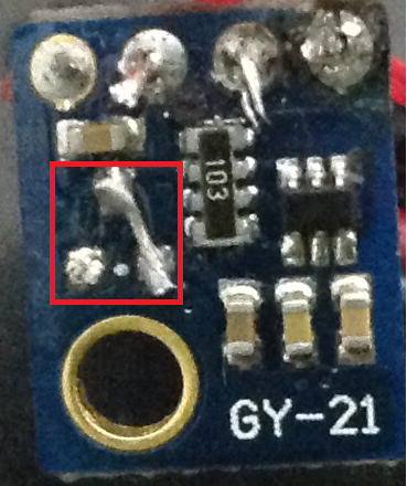
Then I ordered this breakout for future nodes: http://www.aliexpress.com/item/New-HTU21D-Temperature-and-Humidity-Sensor-Module/1970355069.html?ws_ab_test=searchweb201556_1_79_78_77_80,searchweb201644_5,searchweb201560_1 that one doesn't seem to include any additional circuits (other than the pull up resistor and safety? resistor).
-
@korttoma said:
Speaking of the Si021, has anyone tried to use 2 Si7021 sensors on the same node?
Since the i2c address is hardcoded I see two ways of doing this:
-
Power the two sensors from gpio pins (instead of connecting them to vcc, connect each to a separate gpio pin), when you want to read one sensor you put one high and the other low. I'm not really sure if this will work at all.
-
Use a soft i2c library like this one: https://github.com/todbot/SoftI2CMaster that way you have two sets of i2c pins. I'm pretty sure this one should work.
-
-
@n3ro said:
Big THX,
now i have understand how to use the si7021 :)
Reading works great!
But the sleeping current is very high ~1500uA
If you got this breakout: http://www.aliexpress.com/item/Industrial-High-Precision-Si7021-Humidity-Sensor-with-I2C-Interface-for-Arduino/32340228487.html?ws_ab_test=searchweb201556_1_79_78_77_80,searchweb201644_5,searchweb201560_1 it includes a 3.3v regulator and level shifting so you can actually use the sensor with a 5v arduino but it consumes quite a bit of current (60uA in the ones I got) even when idling.
What I did was desolder the regulator and solder a small wire to bypass it (sorry for potato quality pic).
Then I ordered this breakout for future nodes: http://www.aliexpress.com/item/New-HTU21D-Temperature-and-Humidity-Sensor-Module/1970355069.html?ws_ab_test=searchweb201556_1_79_78_77_80,searchweb201644_5,searchweb201560_1 that one doesn't seem to include any additional circuits (other than the pull up resistor and safety? resistor).
-
@riataman said:
with a 5v arduino
Hey =)
the operating voltage of this component is 1.9 to 3,6 v. not 5v =)But the idea to remove the regulator to save a little bit energy is cool. i will try it =)
@n3ro said:
@riataman said:
with a 5v arduino
Hey =)
the operating voltage of this component is 1.9 to 3,6 v. not 5v =)That's true for the individual SI7021 IC, but in the breakout the regulator steps down the voltage to 5v and additional circuitry does 3.3<->5v level shifting. I have tested that particular breakout with a 5v arduino and it works just fine.
Hello! It looks like you're interested in this conversation, but you don't have an account yet.
Getting fed up of having to scroll through the same posts each visit? When you register for an account, you'll always come back to exactly where you were before, and choose to be notified of new replies (either via email, or push notification). You'll also be able to save bookmarks and upvote posts to show your appreciation to other community members.
With your input, this post could be even better 💗
Register Login