💬 Air Humidity Sensor - Si7021
-
This thread contains comments for the article "Air Humidity Sensor - Si7021" posted on MySensors.org.
-
Vice-versa, the link to the 5V module leads to a 3V (well, 1.9V to 3.6V) sensor unit
-
This post is deleted!
-
Vice-versa, the link to the 5V module leads to a 3V (well, 1.9V to 3.6V) sensor unit
@mark-hansen I checked all links (Ebay & Ali) and they all link to the correct modules.
The sensor might support 1.9-3.6V, but the modules are for 3.3 and 5.0V IO levels respectively. The blue modules have a component marked 662K at the bottom, which is a XC6206P332MR voltage regulator. The 6-pin component next to it is a level shifter so the module operates at 5V levels on the outside, and 3.3V to the SI7021.
So please, explain why you think the links are wrong.
-
I had the problem that the code wouldn't return when calling sensor.getCelsiusHundredths() while using the linked library. It works with this library:
-
Hi, when making this sensor battery powered (and thus enabling "#define REPORT_BATTERY_LEVEL"), I get the verification error of "Vcc.h: No such file or directory". How can I solve this?
@Sebex The Si7021 guide mentions that you have to install the Arduino VCC library (link to GitHub) if you want to use this feature:
Example
This example uses the Si7021 library, which is included in the MySensors external examples. If you choose to report battery level to the gateway (by defining REPORT_BATTERY_LEVEL at the top of the sketch) the Vcc library is also required. Please install the librarie(s) and restart the Arduino IDE before trying to compile.
It might be a good idea to add a link to the library in the article itself, since it doesn't make clear which library is required for this.
-
@Sebex The Si7021 guide mentions that you have to install the Arduino VCC library (link to GitHub) if you want to use this feature:
Example
This example uses the Si7021 library, which is included in the MySensors external examples. If you choose to report battery level to the gateway (by defining REPORT_BATTERY_LEVEL at the top of the sketch) the Vcc library is also required. Please install the librarie(s) and restart the Arduino IDE before trying to compile.
It might be a good idea to add a link to the library in the article itself, since it doesn't make clear which library is required for this.
@BearWithBeard the Vcc library is present in MySensorsArduinoExamples, so if MySensorsArduinoExamples is installed, Vcc will be available.
Dependencies is a mess, which is why MySensorsArduinoExamples is in a separate repo. We (the community) has not yet found a good way to handle dependencies.
-
Hi there,
I've a pro mini 3.3V with a si7021 and a Li-ion 3.7V battery.
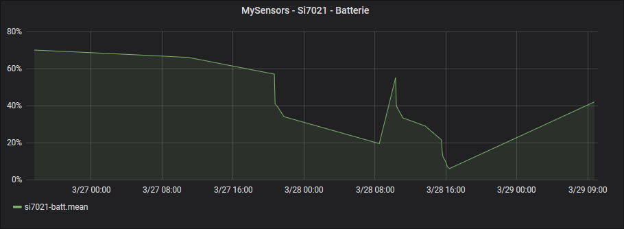
I'm using the VCC library, but the reported values are weird: the remaining battery value drops a lot, and if I reset the board, it jumps back to a more normal value.The battery is connected to the VCC pin on the arduino.
A regulator (LM2936) powers the si7021 and the nrf24.Here is a graph of the battery level. Pikes appear when I reset the arduino.
Isn't the 2 resistors method more accurate?
Thanks!
-
Hi there,
I've a pro mini 3.3V with a si7021 and a Li-ion 3.7V battery.
I'm using the VCC library, but the reported values are weird: the remaining battery value drops a lot, and if I reset the board, it jumps back to a more normal value.The battery is connected to the VCC pin on the arduino.
A regulator (LM2936) powers the si7021 and the nrf24.Here is a graph of the battery level. Pikes appear when I reset the arduino.
Isn't the 2 resistors method more accurate?
Thanks!
-
@Yveaux thanks for your answer.
I used the sketch on the Mysensors'si7021 page, so the vcc level is read at the end of the loop, before going to sleep and after sending the temp/hum values.
The only modification I made are setting up the voltage values.
As my 3.7V Li-Ion battery is at 4.2V when fully charged and at 3V when almost completed discharged, this how I configured it in the sketch:#ifdef REPORT_BATTERY_LEVEL #include <Vcc.h> static uint8_t oldBatteryPcnt = 200; // Initialize to 200 to assure first time value will be sent. const float VccMin = 3.0; // Minimum expected Vcc level, in Volts: Brownout at 1.8V -> 0% const float VccMax = 4.2; // Maximum expected Vcc level, in Volts: 2xAA fresh Alkaline -> 100% const float VccCorrection = 1.0; // Measured Vcc by multimeter divided by reported Vcc static Vcc vcc(VccCorrection); #endifI didn't apply any correction because read and reported VCC was very close, and I'm just testing this for now.
I didn't removed the onboard regulator nor the power led for now. Isn't the regulator only used when applying voltage to the RAW pin?
@bebr said in 💬 Air Humidity Sensor - Si7021:
Your setup looks allright.Isn't the regulator only used when applying voltage to the RAW pin?
Yes it is, but I'm not sure what will happen if you source 3v3 via its output pin.
Anyway, I doubt if this could cause the effect you're seeing. -
Ok, do you need my schematic, to make it clearer?
I've planned to removed the onboard regulator (and power led) on my production board. But this one is for testing so I leave it untouched.
So currently the regulator, is obiously external.
Thanks again, any help appreciated, otherwise I'll use the 2 resistors method.
-
And now, without resetting, the battery level has jumped from 23% to 47%. This last seems to be correct according to the measure of 3.673V, directly taken on the battery.
-
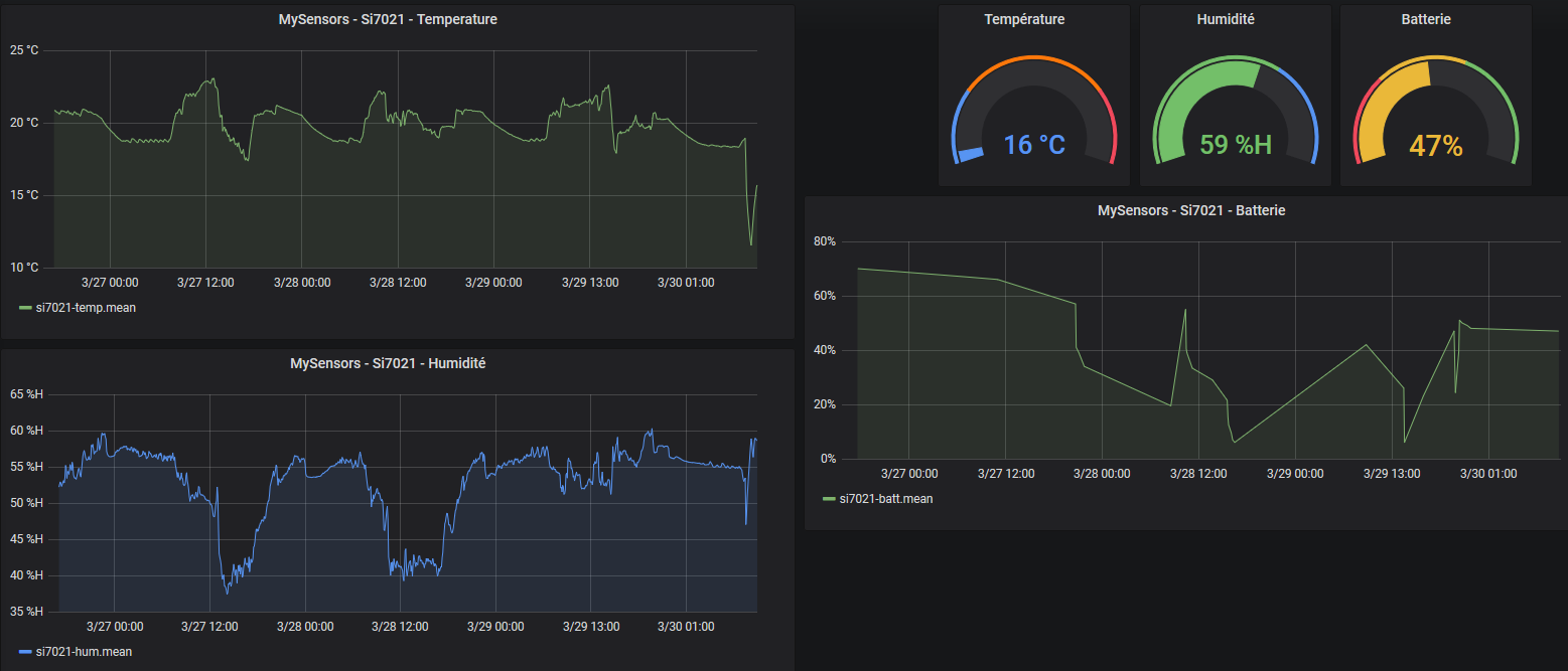
@bebr could it be temperature related? I have noticed that the voltage in my nodes increase when the sun is shining on them.
@mfalkvidd I thought of this too, but I opened the windows this morning, 11°C here this morning, and the battery level stayed around 50%.
Here are some graphs showing it's not temperature related:
Hello! It looks like you're interested in this conversation, but you don't have an account yet.
Getting fed up of having to scroll through the same posts each visit? When you register for an account, you'll always come back to exactly where you were before, and choose to be notified of new replies (either via email, or push notification). You'll also be able to save bookmarks and upvote posts to show your appreciation to other community members.
With your input, this post could be even better 💗
Register Login