DIY Outdoor LED


  • Hero Member

    So I was wondering about installing some LED lights on the front porch and I thought that perhaps some of you guys may have some input and prior experience with this.

    What I have is a 45W 12V DC power supply so that is basically the budget I have to work with. I also use this to power MySensors units around the same area. My main motivation for doing this is to get the most out of this power supply and I bought a slightly beefier model in anticipation of powering these LEDs. My other motivator is cost of course. Commercial lights are ridiculously priced, are often designed to be sunk into the surface instead of mounted externally and they are no better than your average Ebay LED since replacing the "bulb" requires soldering in a new SMD LED. Or they are just set too high, eating up too many watts, run on 230V AC or use old LED tech with low lumens/watt.

    What I want is a series of LEDs run at 1-2W that can be spread out and cover the entire front of the house. I saw all those CREE LEDs on Ebay soldered to metal-core printed circuit boards (MCPCB) and thought that could be a great way to fix the problem on a budget. Either that or buy the MCPCB and SMD LED separately. There are also borosilicate wide-angle lenses that may be suitable as a casing. All the lights will be mounted in the ceiling and will be reasonably well protected against the element already. If I can find a reliable design that looks nice I might add dozens of lights around the house as well as in the garden.

    Any particular model or brand of LED to look for? I want as many lumens / watt as possible obviously, and it would have to be at lets say 600-700mA / LED no more. I noticed most LEDs seems to performs their best lumens/watt at low amp inputs so at least that is fortunate. It would have to be a warm white light and a high CRI. Particularly the latter seems to be the catch with many Ebay LEDs, at least the pre-soldered ones. They never mention CRI so I figure that they'd have to be the worst of the bunch, no better than 65 or 70. But perhaps it doesn't matter for the purpose?

    Haven't considered a driver yet or how exactly to interface these with MySensors (whether simply an on/off proposition or a dimmer controller). I do know I will have these lights work in conjunction with one or more motions detectors as well as my Raspberry Camera that covers the front of the house.


  • Hero Member

    Can't really help, but I am interested in what you end up with..


  • @bjornhallberg I'm new to the forum and just got my Arduino today (still waiting for the other parts to arrive for my project), so I can't yet explain how to write any code, however I understand the following:

    • 1 - The design of your circuit has little to do with the sensor you use to operate them, thus you can decide on which LEDs to buy based on power consumption only (and maybe the capability to dim with burning).

    • 2.- Then you can build your circuitry and plug it in normally to the power source.

    • 3.- After you know the circuit works properly, THEN you bring the sensors.

    Basically you would use these sensors to control when the lights turn on/off, and that can be done in a variety of ways and with an array of different sensors.

    In my case, for example, I'm trying to open/close a circuit based on proximity, pretty much what you want, but I plan on doing so using a bluetooth module for the Arduino that pings my phone to see if its around, given the phone is found, the Arduino would emit voltage in a pin and that should (I still have no idea, but somehow) open the circuit and stop it from functioning, given the phone is out of reach, the voltage is stopped, and the circuit goes back to operating normally.

    In your case I don't think this would be a good approach because you want it to work whenever someone comes close, so maybe PIR sensors, or pressure plates, or IR sensor in the walkway or any other sensor you can use to identify someone's around.

    I would recommend you go and complete steps 1 and 2 and then come back with an idea of how you want to interact with your new circuit and the folks here will help you out on which sensors are better suited for you.


  • Hero Member

    @PedroC88 Yes, you're right, but this project only works if I can find good, cheap LEDs in the first place, and some clever and seemly way to mount them. I'm not even close to an actual circuit, drivers or the sensor network. I have some bad experiences buying LEDs of different sorts on Ebay and the esthetics are very important. Not to mention that things don't fail after a couple of weeks. The actual electronics will have to come later.

    I guess what I'm looking for right now:

    1. A specific recommendation for LED (i.e. "CREE XM-L" or whatever)
    2. Whether buying them from Ebay is reliable or a recipe for disaster (i.e. are the LEDs genuine and is the CRI any good).
    3. Some way to mount the LEDs in the ceiling (a case), and disperse the light that doesn't look horrible (including whether you'd need more of a heat sink).


  • @bjornhallberg said:

    )

    In that case I don't think this the right place, as the site is mostly intended to help you controlling sensors and actuators using (mainly) Arduinos. The only thing I can tell you is that buying through ebay (though I prefer Amazon) is usually reliable, provided you can return the purchased, defective item within 30 days of purchase. In my case, since I live outside U.S., that's usually an inconvenience due to local taxes.

    When you're done with that, if you still need help with automating the operation of your LEDs array, let us know.


  • Contest Winner

    I'd recommend to buy all leds that you plan to use in a single shot because leds will have slightly different colors even when buying quality ones. If you have a look in the datasheets of e.g. osram leds you see that there are more than 20 different colors (shades of white). If you buy 1000 of leds you are able to choose exaxtly matching colors. But we as normal people are dependent on the distributor. That means you should get closely matching colors if you buy your leds in a single shot... at least the ones you will see at the same time.
    best regards


  • Hero Member

    They never mention CRI so I figure that they'd have to be the worst of the bunch, no better than 65 or 70. But perhaps it doesn't matter for the purpose?

    I think a good CRI is important for the kitchen, with a low CRI you have the chance that food does not look that attractive anymore. A low CRI most of the times translates in poor red colors but I think that is not soon a problem for the front of the house.

    For much more background see A close look at the Color Rendering Index (CRI, or Ra).


  • I have done something like this on my shed, to light up the pathway running beside the it.

    I bought 20 1W LED's on aliexpress http://www.aliexpress.com/item/New-10x-1W-High-Brightness-LED-Flood-Light-Lamp-Bulb-90-100Lm-Warm-White-3-2/32223688453.html (they can be found cheaper a piece if you buy more)

    Only diffence is, that I get the 12v power from a car battery, but it's still 12v. (battery charged by solarcells) The 4 serial connected LED's used to light the pathway connects to 12v via a relayswitch controlled by a arduino mini pro. Which again is controllede via openhab MQTT.


  • I am trying to do something similar but I plan to embed controller in each one of these nodes along with motion and ambient light sensor.

    So far the most cost effective seems to be to take one of these and modify it for 12V and add mySensor circuit to it.

    http://www.ebay.com/itm/10W-20W-30W-50W-Led-High-Flood-Light-Lamp-Outdoor-12V-110V-Day-Warm-White-RGB-/191027296073?pt=LH_DefaultDomain_0&var=&hash=item2c7a1d3749

    How do I power MYS board with 12V?

    -AM


  • Hero Member

    So, the LEDs I ordered from Ebay got lost in shipping. What are the odds. Happened maybe two times out of 250 Ebay orders. I've been refunded of course but I now doubt I will continue down this track. Thinking of going back to 230V and relays instead + some cheap fixtures from IKEA.

    @activemind Not a bad idea with the flood light housing, seeing as it is so difficult to find outdoor housings. I just hope they used stainless screws and bolts.

    The Arduino Pro Mini could theoretically accept 12V on the RAW pin. If that is a good idea and a long term solution I don't know. Buck converters are pretty cheap and have worked with the Pro Mini and Radio Module when I've tested them. But I'm sure if I had looked at them using an oscilloscope I would feel different.


  • Hero Member

    I have a few nodes of Pro Minis that I power with 12VDC on the RAW pin. Have not had any trouble so far but I use high quality 12VDC power supplies that do not exceed that 12V. Exceeding 12VDC will burn the regulator on your Pro Mini. To be safe you could always add another regulator between the 12V supply and the raw pin.


  • @bjornhallberg - I looked at Ikea stuff but its too hard to modify. I did have 2 of the flood lights come in...they are 110V version, plan on disassembing one tonite. I will the pics up.

    What I am thinking is take these housing and modify the LED if need be and stick one of these MySensor circuit in there. I think all can be done for < $20.


  • @korttoma - Good to know that 12V should be fine because as I posted above, I plan on using the above housing and modify it for 12V DC operation. I have a server grade high amp 12V DC power supply that I plan on using for all these lights and it would be good if I could use the same 12V for powering mySensor node as the LEDs.

    -AM


  • Hero Member

    I can't say the same as @korttoma --- I burned some pro minis (in fact, cheap clones) by applying 12V at RAW pin. I think the on-board regulator of my clones has 12V as absolute maximum. And I had to learn it in the hard way... 😉

    After i to put a 78L05 between 12V and Arduino's VCC pin (as well as a 78L33 between 12V and radio), everything worked pretty well.


  • Hero Member

    @rvendrame yeah, that is how I would recommend to do also. An additional regulators are worth it, just to be safe.


  • Bringing back and old thread from the dead as I have some time now to spend on this.

    Did some more research on Amazon and ended up ordering these LED lights

    http://www.amazon.com/Lemonbest®-Outdoor-Decorative-Lighting-Landscape/dp/B012VLSYJE?ie=UTF8&psc=1&redirect=true&ref_=oh_aui_detailpage_o00_s00

    Planning on using MYS board to control these.

    http://forum.mysensors.org/topic/207/my-sensorboard-mys-1-0beta

    I have 2 questions:

    1. These are 12V and MyS board can take 12V input too. So I can power them off using the same 12V wire. Shall I use a relay to control these lights ? Couldnt find the current draw but I plan on measuring it once I get them in.

    2. Should I try to embed the myS board in the light case or look into an external waterproof plastic box? These are going to be outdoors.

    -AM


  • Mod

    @activemind said:

    1. These are 12V and MyS board can take 12V input too. So I can power them off using the same 12V wire. Shall I use a relay to control these lights ? Couldnt find the current draw but I plan on measuring it once I get them in.

    They are rated for 5W. 12V/5W=2,4A

    Edit: NO, 5W/12V=0.42A. My bad.


  • Mod

    @activemind said:

    1. Should I try to embed the myS board in the light case or look into an external waterproof plastic box? These are going to be outdoors.

    The case seems to be made if aluminum. That will probably block radio signals. So if you're planning to use radio, go for a plastic box.


  • Thanks for the feeback. You make good points. I will plan for an external waterproof box for all mysensors circuitry.

    Does using a FET sound good or shall I use a relay?

    Something like this should be pretty inexpensive..

    http://www.ebay.com/itm/Mos-fet-40v-190amp-for-3k-5k-6k-main-baord-of-12v-power-inverter-/322048034708?hash=item4afb8f0794:g:piQAAOSwHgVW8Ps0&vxp=mtr

    -AM


  • Mod

    There is no information on which mosfet in the ebay listing. I would one that has a name/number so the data sheet can be looked up. The MySensors store recommends IRLZ44N.

    Downside with mosfet: can become hot, might need a heat sink
    Upside with mosfet: can be used to dim the lights

    By the way, how are you planning to get the power to the units? 12V from your house into the garden? In that case you might get problems if your garden is large, transferring power over long distances with low voltage is hard.


  • Will the FET get hot even with 2.4A when its rated for much more?

    I am thinking of building one node and trying it out to see if there is any fallout. This will be for my landscape lights so its not like it will be running 24/7.

    The plan IS to run a 14/2 wire running 12V. I could do 12/2 if the voltage drop is too bad. My runs should not be obscenely long...I guess I will have to just try and see what the drop is.

    Thanks again for all your feedback.

    -AM


  • Mod

    @activemind said:

    Will the FET get hot even with 2.4A when its rated for much more?

    Probably not. As long as you check the rating you should be fine.

    The plan IS to run a 14/2 wire running 12V. I could do 12/2 if the voltage drop is too bad. My runs should not be obscenely long...I guess I will have to just try and see what the drop is.

    14 AWG has a resistance of 0.00829 ohm per meter (source). Assuming you have 15m from the outlet to the light, the resistance in the cable will be 0.2487 ohm (0.00829 * 15 * 2). At 2.4A that will result in a voltage drop of 2.4 * 0.2487=0,60V. That shouldn't be a problem.

    If the distance from the outlet to the lights is longer, and you want to connect multiple lights without running multiple cables, the calculation doesn't look very good. Let's say the cable needs to be 30m and you want 5 lights, then we have a cable resistance of 0.00829 * 30 * 2=0.5 ohm and a voltage drop of 2.4 * 5 * 0.5=6V ❗
    12 AWG will give you 0.00521 * 30 * 2=0.3126 ohm and 2.4 * 5 * 0.3126=3,75V voltage drop which also might be too much.


  • I would put my distance around 20m so that should be okay but I DO plan on putting multiple of these on a single run hence larger current!

    I really dont want to do multiple runs.

    Two options:

    1. I need to see how bright the light is with < 12V ?
    2. Use some regulator to bump up the voltage at the location. I will be building a seperate box anyways to house the FET and MySensors circuitry, so maybe put a regulator there?

    What do you think?

    -AM


  • Mod

    Option 2 would require larger current (2.4A at 12V will require at least 4.8A at 6V) so the problem just gets worse. Better to increase the voltage, maybe run 24V and regulate down to 12V at each light?


  • @mfalkvidd
    But i already have server grade 12v power supplies and i dont want to buy new ones.

    Is the LED really going to draw 2.4A? I will hook up one today and measure.

    What's the max safe amount of current i can carry on 14/2 LV wire?

    If push comes to shove, i might do multiple runs 😢

    -AM


  • Hero Member

    @activemind

    Each led would draw around 410ma
    5/12=.416


  • Mod

    According to http://www.powerstream.com/Wire_Size.htm the limit for 14 awg is 5.9A.


  • Mod

    @Boots33 correct! I edited my previous calculation. Sorry for misleading you @activemind My voltage drop calculations are off by 5x so you will be able to use 5 lights instead of 1 at 2.4A. That means you'll only get in trouble if you plan to use 20+ lights.


  • @mfalkvidd

    Phew! I think i should be okay as i dont plan on putting more than 10 on a string.

    -AM


  • Ended up blowing the regulator on a 5V pro mini when powered at 12V. Maybe its the "clone" part from china that is causing this but it gave out smoke and finally died when powered at 9V.

    Going to assemble another 5V pro mini and power at 5V to test the board and circuit.

    Thinking about putting a hefty 150R 1W ressistor before feeding 12V to RAW in final circuit.

    Thoughts?

    -AM


  • Hero Member

    @activemind

    You could also use an external regulator module to supply the 5v. at the moment you are running right on the pro mini maximum voltage which in my mind is never a good thing for long term reliability. I have used these modules with great success, they work with a wide level of input voltage and can be adjusted, so can be set to 5v or 3v output . They are quite cheap as well so if you have the room they may be worth a look.


  • Yeah, those would work good and I can feed 5V rather than 12V ar RAW pin.

    How are these adjusted to output 5V?

    edit: nevermind, I see the pot screw to adjust the output voltage.

    -AM


  • assembled another pro mini board and powered it using 5V wall wart this time, no 3v3 on the board. I think I blew 662K part too.

    Let me try replacing it.

    -AM


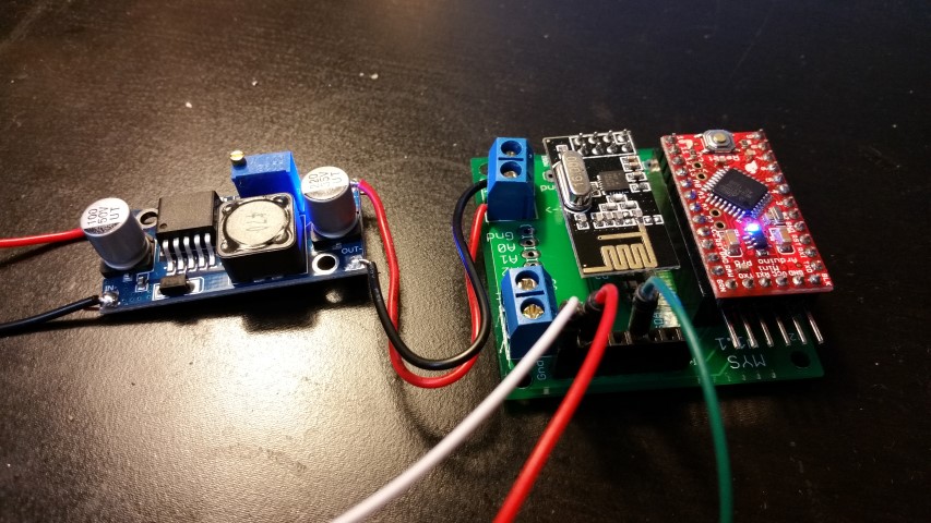
  • replaced the 662K part and now it seems to be working fine. I dug up my stash and found one step down converter like above. Let me power the node using it and see how it goes.

    -AM


  • Powering a motion sensor sketch using the buck converter above. I wish I had my 12V relays in...

    Here is a pic:

    0_1462699296292_20160508_022105.jpg


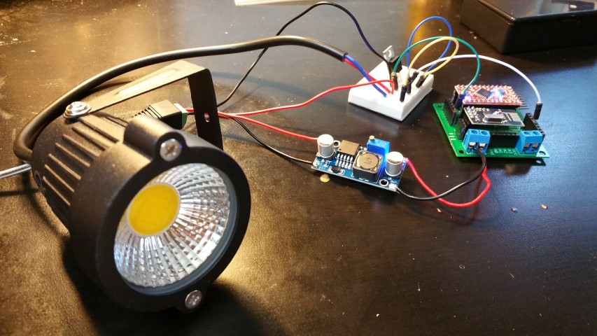
  • Connected the whole thing up....working nicely.

    Though I do see a flicker when I try to dim it...

    0_1462849176708_20160509_194454.jpg


  • Figured out the flicker issue, it was the power supply. I was using a puny 750mA wall wart which could handle the PWM duty cycle. Once I put my hefty 12V power supply, its behaving fine.

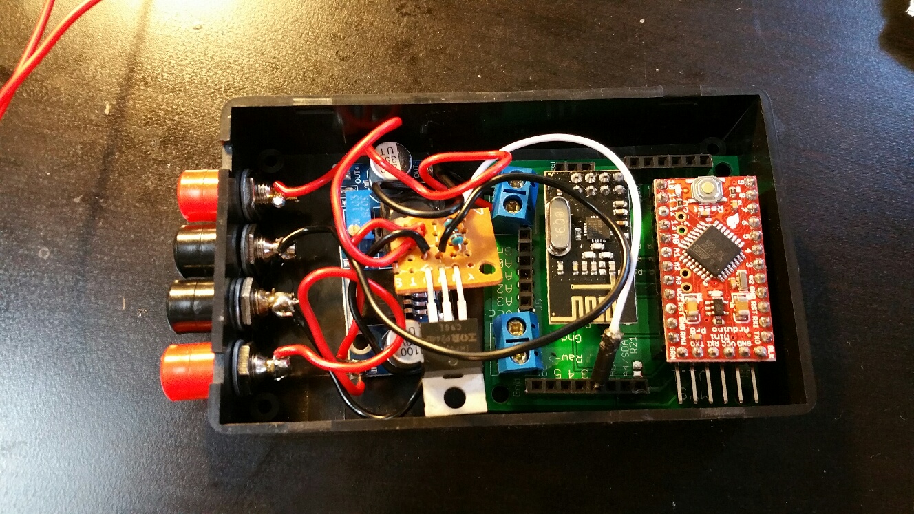
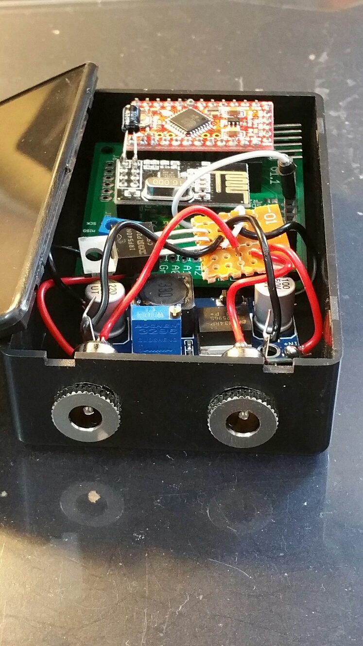
    I built a perfboard and the FET and was able to fit everything in a plastic DIY box from ebay.

    How do I weatherize this because this will be outside exposed to elements? Also thinking of making some holes in the box to vent out some heat.

    Whats the best way to do this?

    -AM


  • Ready to rock n roll...

    Packaging is done though I dont know how weatherproof this is going to be..0_1463108803840_20160512_183825_resized.jpg


  • Hero Member

    @activemind looks good. I use these boxes outside. Just turn it upside down and your circuit should be protected from rain. I'm not sure your connectors will survive on the long run. (in fact i'm sure they won't 😉 )


  • Thanks for your response. Whats my other options for connectors? I really dont want to hardwire it.

    -AM


  • Hero Member

    @activemind you could either:

    • use waterproof connectors
    • don't use connectors and apply some sealing kit
    • ignore the rusting and take action when it stops working 😉


  • I think i will go with option#3 for now. These are landscape lights...world won't end if they go off after some time.

    Lets see how long it lasts and if its too short then i could look at other options.

    Plan to build 9 more of these ( total 10) and run some 14/2 LV this weekend. Will post pics when done.

    I tested the light last night at its prospective location and it works like a champ. Nrf range aint that bad for the price ☺

    -AM


  • Mod

    Something like this might be useful if you decide to go for waterproof connectors https://www.adafruit.com/product/743


  • @mfalkvidd Those connectors look intersting, let me look at them in more detail.

    First one deployed today. Scheduled to come on at dusk and turn off at 10PM through Vera.
    Will update with a pic in action.

    Went ahead and ordered 8 more and now need to assemble the "mysensor boxes" for them.

    -AM


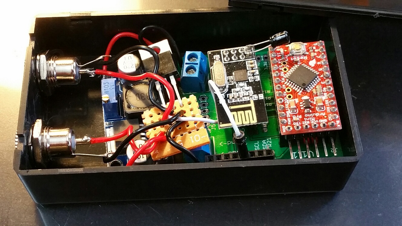
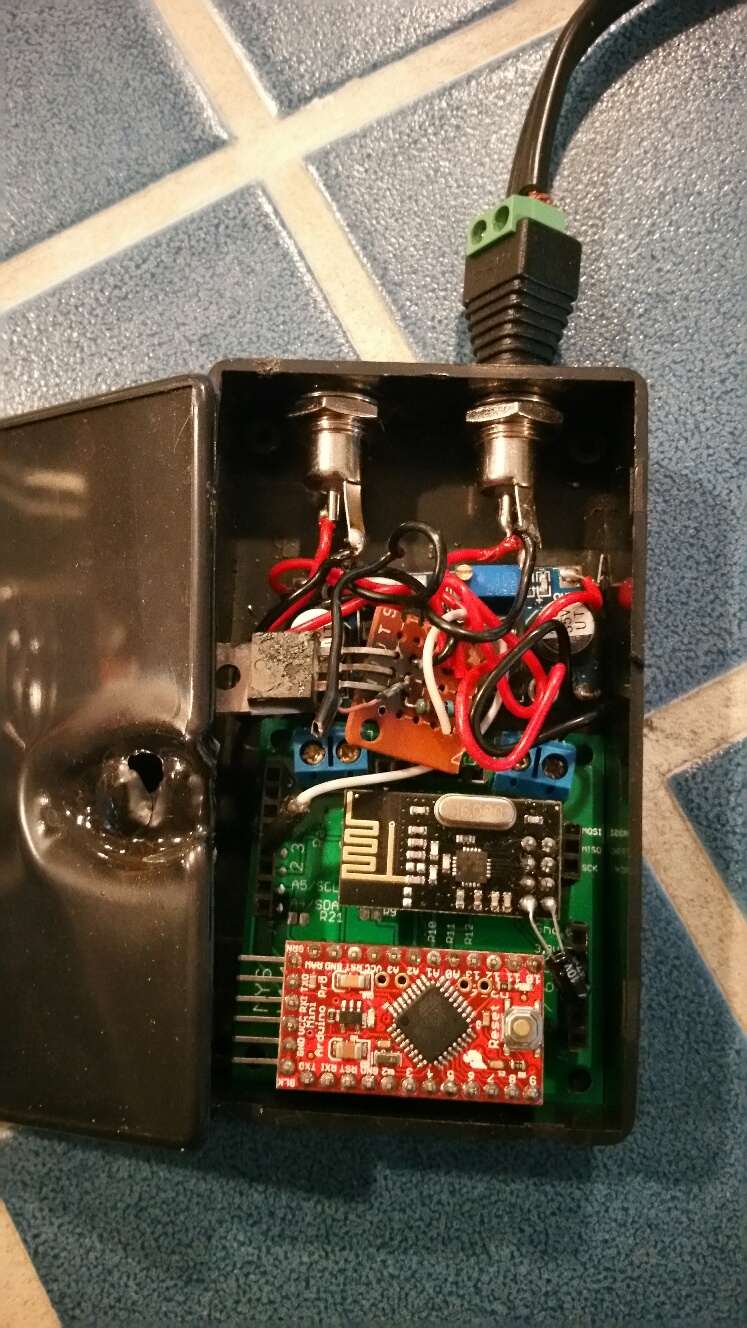
  • I changed the banana plugs to regular DC 2.1mm plugs and it looks less cluttered now.

    Deployed it yesterday. Looks good.

    Will upload pics if someone is interested.

    -AM


  • Hero Member

    Pics are always good. Please do upload


  • Here are some pics of the "final" product:

    Thanks to everyone for their input.

    -AM

    0_1465148123345_20160605_103454_resized.jpg 0_1465148136827_20160605_103520_resized.jpg


  • So I deployed 5 more of these yesterday, so I have a total of 6 on the chain now.

    The total current draw is ~5A at 12V...not bad!

    Though I have an issue where the lights will go off for a little bit and then come back on.

    Almost all of them are doing this and it doesnt happen at the same time so its not that the power is interrupted.

    Makes me think as if the LED is heating up and shutting down and then when it cools down after a bit, it comes back on.

    I tested them prior to deployment to make sure that they worked but didnt run them long enough that they would heat up. Plan on putting up one on the bench and leave it on longer to see if it does that.

    But overall, not bad landscape light for 10 bucks!

    -AM


  • Update: The landscape light are programmed to come on in the evening and they did not turn on this evening. Further investigation yielded this:

    0_1466478544548_20160620_201011_resized.jpg

    0_1466478552295_20160620_201046_resized.jpg

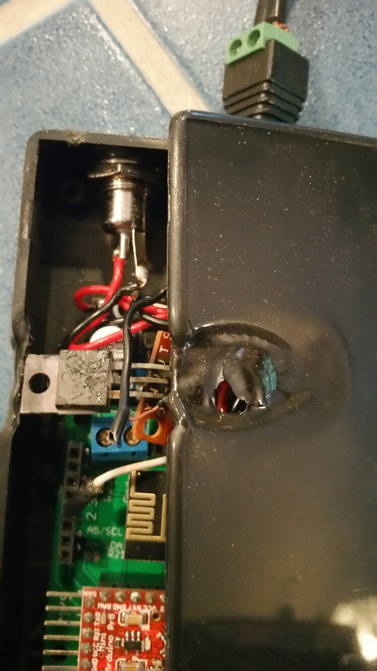
    The FET was touching the plastic case and melted it 😞

    -AM


  • Mod


  • Hero Member

    @activemind are you dimming the led or only switch it? A (swich) fet in full saturation should have an internal resistance of less than 0.1 ohm. It would be hard to get it heated that much with a current in the range of 1 amp..
    It could well be that your fet is not in full saturation. Take a look at the data sheet..


  • @mfalkvidd said:

    This might help a bit http://www.aliexpress.com/item/10pcs-Free-Shipping-Aluminium-TO-220-Heatsink-TO-220-Heat-Sink-Transistor-Radiator-TO220-Cooler-Cooling/32684240364.html

    Yup! I have them on order from China. Will try but I think I need to perforate the box too. Its drwaing ~5A which is amlost 60W. Maybe a little too much for a totally closed box!

    -AM


  • @AWI said:

    @activemind are you dimming the led or only switch it? A (swich) fet in full saturation should have an internal resistance of less than 0.1 ohm. It would be hard to get it heated that much with a current in the range of 1 amp..
    It could well be that your fet is not in full saturation. Take a look at the data sheet..

    I am dimming as well as turning them on/off. There are 6 such lights on this FET and when all are on, the draw is around 5A. I am guessing thats a little too much for this tiny heatsink in an enclosed box. Need to change the heatsink and perforate the box.

    Thanks for the datasheet reminder. Let me go back and check whats the power I am dissipating when dimming these lights.

    -AM


  • Mod

    Yup! I have them on order from China. Will try but I think I need to perforate the box too. Its drwaing ~5A which is amlost 60W. Maybe a little too much for a totally closed box!

    Most of the power will be dissipated in the lights. The power dissipated in the FET is the FET's resistance * current^2. If you are using a IRLZ44N FET I think that means 0.025 * 5^2 = 0.625W if you give the FET a signal of 5V. (0.025 ohm is the Static Drain-to-Source On-Resistance from the datasheet)


  • @mfalkvidd said:

    Yup! I have them on order from China. Will try but I think I need to perforate the box too. Its drwaing ~5A which is amlost 60W. Maybe a little too much for a totally closed box!

    Most of the power will be dissipated in the lights. The power dissipated in the FET is the FET's resistance * current^2. If you are using a IRLZ44N FET I think that means 0.025 * 5^2 = 0.625W if you give the FET a signal of 5V. (0.025 ohm is the Static Drain-to-Source On-Resistance from the datasheet)

    Heat dissapation in the lights is another issue I need to look into because with this new batch I ordered, they have been turning off after like 5 mins and then come back on by themselves. I think the heat sink on this new batch is not that good because the last batch did not do this.

    I am using them at 12V so the power would be ~4W. Not too much but still enough to get the sink hot!

    -AM


  • Mod

    I am using them at 12V so the power would be ~4W. Not too much but still enough to get the sink hot!

    The voltage makes no difference. 5A is still 5A.


  • @mfalkvidd said:

    I am using them at 12V so the power would be ~4W. Not too much but still enough to get the sink hot!

    The voltage makes no difference. 5A is still 5A.

    you are right 🙂 brain fart


Suggested Topics

1
Online

11.2k
Users

11.1k
Topics

112.5k
Posts