How to read frequency and SWP output from watermark sensor
-
Hello All,
I choose to measure soil moisture with a Watermark sendor and an electric interface for Watermark (SMX)
The SMX give 3 options to read the result: Voltage, courent and frequency.
Look at the page 3, first schema.I created my breadboard but I have not test it yet because I no expertise to develop a code to read the frequency with a digital read.
Someone can share an expemple or an experience?
Thank a lot
-
Hello
Ir's not easy has you say.
The doc say:A special circuit is needed to measure the electrical resistance of the Watermark sensor. DC currents must not be allowed to flow through the wet part of the circuit, or else irreversible reactions will occur and spoil the readings. AC excitation avoids these problems, by reversing the polarity of the current many times per second, so that no net reaction takes place at either electrode. The circuit must also isolate the sensor electrodes from galvanic currents in the soil environmentWe need two analog pin, one to measure in one sens, and the second when we alternated to power. I spend so much time on this without a good result, that I would appreciate to do it with the SMX electrical interface for Watermark.
I am tryinf to find thw right connection with an Arduino to measure the frequency, with pain. Some of you has an experience with it?
@pierrot10 I am confused with your question and what parts you have available.
1 If you only have the Watermark Sensor and No Interface.
This means you do need to make the interface yourself using at least two control pins to supply the ac power to the sensor, and you need to write the code in a way that will protect the sensor from the possiblity of the damaging conditions.
You also have read voltages from the sensor leads and process it to get some useful readings. ie soil resistance.2 if you have the Watermark Sensor and the Matching SMX interface then node is easy, as you only have to process the final signal from the SMX interface.
a) the simplest way would be set the SMX to mV output and then just read that with the node and map it your required values, from the data sheet normal range is 0.2V to 1.0V with 1.7V sensor shorted.
The datasheet has the mapping for output voltages to soil resistance readings.b) Setting the SMX to frequency mode and reading it is also not so difficult if the node is not too complex, But i cannot see any advantage unless in a electrically noisy environment, or the sensor is a long distance from the node.
looking at the pulseIn() function will give an method of reading the pulse width and then calculating the frequency
To get the frequency you can use f = 1 / 2*pulse_width equation
The datasheet shows the range between 50Hz and 10kHz that pulse with of 10mS to 50uS so you will need a 16mHz processor to read this.c) The SMX can be used in current output mode but more difficult to monitor with a basic arduino without extra hardware especially as the range is 0.2 to 1mA, so i would not recommend this unless a more robust design is required and extra cost justified
-
Hello
Ir's not easy has you say.
The doc say:A special circuit is needed to measure the electrical resistance of the Watermark sensor. DC currents must not be allowed to flow through the wet part of the circuit, or else irreversible reactions will occur and spoil the readings. AC excitation avoids these problems, by reversing the polarity of the current many times per second, so that no net reaction takes place at either electrode. The circuit must also isolate the sensor electrodes from galvanic currents in the soil environmentWe need two analog pin, one to measure in one sens, and the second when we alternated to power. I spend so much time on this without a good result, that I would appreciate to do it with the SMX electrical interface for Watermark.
I am tryinf to find thw right connection with an Arduino to measure the frequency, with pain. Some of you has an experience with it?
@pierrot10 Sorry i forgot the example code.
The very simplest example using pulseIn for frequency measurement
// global var
int signal_input_pin = 4;  // Sensor pulse pin


void setup() {
  // put your setup code here, to run once:
  pinMode (input, signal_input_pin);
}


void loop() {
  // put your main code here, to run repeatedly:
  float Signal_Freqency = freqencyMeasure(signal_input_pin)
}


long freqencyMeasure(int input_pin) {
  // if mark-space ratio is equal then only one measurement High time or low time and double it is required.
  int HighInput;      // Store high time of wave in microseconds
  int LowInput;       // store Low time of wave in microseconds
  float TotalInput;   // Temp store of total time of duration for one cycle of high and low pulse
  float frequency;    // calculated freqency   1/total time of one cycle.
  HighInput = pulseIn(input_pin,HIGH);
  LowInput  = pulseIn(input_pin,LOW);
  TotalInput = HighInput + LowInput;
  frequency = 1000000 / TotalInput;
  if (HighInput >0 && LowInput>0) return frequency;   // reading valid
  return 0;
 }
Normally you should apply some signal conditioning and take several readings.
-
Dear Hard-shovel
Thank a lot for your explication. That help!
I use freqency measures because the voltage output need to have an input pf 4.5V. My circuit worj with 3.3V even ifI believe it would work.
I created that schema
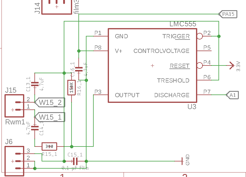 .
.
Watermark is connected to W15_2 and _1
On PA15, I power the watermark with DIO pin of my microcontroller, and then I take the frequency measure on A5 (work as digitalRead). In that way, I controll the power and power the watermark only when I need.I have 3 time that circuit as I have 3 watermarks to measure at 3 different level.
I use that code to get the frequeny
/*
 * GET Watermarksvalue
 */
unsigned long measureSMX(int powerPin, int pinRead, unsigned long timeout){
  #ifdef ST2
    unsigned long duration;
   float percent=0.0;
    sw.digitalWrite(powerPin, HIGH); // (sw = Seesaw board from Adafruit)
    delay(1000);
    //duration = pulseIn(pinRead, HIGH, timeout);
    /*
    while(1)
    {
      //Serial.println( digitalRead(pinRead));
      //delay(1);
    }
    */

    duration = pulseIn(pinRead, HIGH);
    sw.digitalWrite(powerPin, LOW);


    //percent= map(duration,50,10000,0,100);
    percent = duration*100/11000;
    #ifdef DEBUG
      Si.sprint(F("Frequency at "),2); Si.sprint(pinRead,2); Si.sprint(F(": "),2); Si.sprint(duration,2); Si.sprint(F("Hz "),2);
      Si.sprint(F("("),2); Si.sprint(percent,2); Si.sprintln(F("%)"),2);
    #endif
    delay(2000);
    return (int)percent;
  #endif
}
and the measures look good. But my code is very simple in comparaison of your and I would happy to imporve it (and correct/remove error)
Your exemple look very interrestin but why do your need to mesure once with LOW and once with HIGH
HighInput = pulseIn(input_pin,HIGH);
  LowInput  = pulseIn(input_pin,LOW);
I suppose I should do as you demonstrated.
You also mentionned that the microcontroller should be 16Mhz. I supposed it's the minimum requiered?
My microcontroller is a 48Mhz. The micro-controller spped has an important on frequency result/calculation?Thank for helping!
-
Hi pierrot10
Seeing your curcuit it makes sense now, I saw this schematic in the data sheet but did not really look at the details and skipped over the page.
I see you do not have the shunt resistor in the ground supply connection on your schematic so are unable to measure the mV signal. So only the pulse signal is available.
Q1. Do you have a pullup resistor on the pulse signal A1 or have internal pullups on the microcontroller enabled?
Q2. Is there a reason that you switch the V+ into LMC555 but do not switch the Reset (P4) as well from PA15?
Q3 Your code "" percent = duration*100/11000; ""
That does not seem to make sense to me, as when i chart the numbers, it seems to me the most useful range according to the KPa numbers will not be very sensitive with your figures ranging from an intger of 9 down to 0.Also why multiply by a hundred only to divide again, simplify to
percent = duration/110;percent = duration/110;
A Why measure once with LOW and with HIGH
This was to get the correct frequency, As i did not know the mark-space ratio of the pulses was 50%, ie high and low the same duration.
As frequency in Hz is the number of cycles in one second. If we take the time for the High Pulse and the Low pulse and use that to divide one second we get Hz.
If they were not the same then the frequency calculation would be incorrect just taking one reading.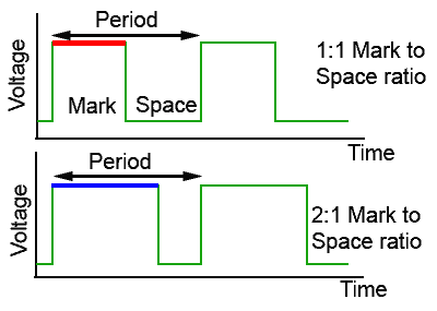
If 1:1 mark space ratio then measuring High or Low and mulitlying by two will give the freqency
ie 50Hz, one cycle takes 20ms, measure high or low at 10ms, 2*10ms = 20ms
frequency = 1/20ms -
more:
if mark space ratio is 2:1 then need to measure both high and low
ie 50hz high = 15ms, low = 5ms
using only high readings 2x15ms = calculated value of 1/30ms = 33Hz
using only low readings 2x5ms = calculated value of 1/10ms = 10Hz
using both low & high 15ms + 5ms = calculated value of 1/20ms = 50Hzi would send the frequency value to the controller if possible as then you have raw data to process with no lose of resolution. Unless your controller can only handle 0-100 percent data.
for example using info from data sheet.
16384 Ohms approx 476Hz = 100 Kpa your calculation = 9
12288 Ohms approx 612Hz = 75 Kps your calculation = 7
8192 Ohms approx 874Hz = 55 Kpa your calculation = 5
6144 ohms approx 1135Hz= 35 kpa your calculation = 4As i do not have a sensor to test it does seem that you may only be getting a good reading of dry to very dry with your scheme. Still that is only a guess as i really have no idea what 100Kpa really means to a plant.
-
One more question
What is the purpose of the J6 connector, as i should think that connecting any cable or meter will effect the capacitance and change the output frequency. -
Dear Hard-shovel.
Realy a great thank for your reply.It's too late now to answer of all of your obersvation (it's 1.30 am at my place), but I will take care of this tomrrow.
Just to answer for this
What is the purpose of the J6 connector, as i should think that connecting any cable or meter will effect the capacitance and change the output frequency.I build the circuit myself and I was not sure about the Film capacitor C15_1. I juts add J6 in case I make a mistake about C15_1. In that case, I can add a different capacitor on J6. But it should remind open and remove it later unless C15_1 (SMD) does not match. I have a doubt about C15_1, but not about the no-SMD capacitor that I can place on J6 holes. ;)
About Q3, yes of course
About Q2. Yes I thought to connect to PA15 instead of 3.3V. I though there is no impact if I keep RESET permanentely to 3.3, but I can have it to PA15, when the DIO of my processor is HIGH to power the SMX circuit.
About Q1: I didnot foresee a pull up resistor on A1 and Ido not know if my microcontroller has one (Adafruit Feather MO adalogger), but I will check it tomorrow.I will better read your additonnal helpfully next comments
Great, thank a lot for your suggestion and comments
Cheers
Thank -
Hi pierrot10
It is mentioned in the SMX instructions and on the ti data sheet it clearly mentions the discharge pin being open collector. I like to use external pullups normally as it gives more control.
check if you have the internal pullup set.The Adafruit Feather MO adalogger looks like a useful board with on-board charger ect
pinMode(pinRead INPUT_PULLUP)I was going to try the circuit on a two pronged eBay sensor, but i cannot find any of the LMC555 or other cmos variants in my hoard of parts.
Best of Luck with the project.
-
@hard-shovel said in How to read frequency output from watermark sensor:
That does not seem to make sense to me, as when i chart the numbers, it seems to me the most useful range according to the KPa numbers will not be very sensitive with your figures ranging from an intger of 9 down to 0.
I am sorry but I was busy with another problem that now I fixed.
First of all. The Analog (A1) has a pull-up resistance.
Secondely, you asked me why I do not use the kPa unit instead of percent.The reason is I do not know how. In fact I know but I can not get a correct value. I followed your recommandation and I use pulseIN HIGH and LOW
HighInput = pulseIn(input_pin,HIGH);
LowInput  = pulseIn(input_pin,LOW);
I tested it while the sensor is in dry, dry soil and it return me 48Hz. I have not add water into the soil, as I need to keep it dry for now. But I believe my code work fine to get Hz
/*
    * Second soluion more precise
    */
    int highInput, lowInput;             // Store high and low time of wave in microseconds
    float totalInput;                     // Temp store of total time of duration for one cycle of high and low pulse
    float frequency;                      // calculated freqency   1/total time of one cycle.
    float swp, wrm;
    float Tsoil=24; //temp
    highInput = pulseIn(pinRead,HIGH);
    lowInput  = pulseIn(pinRead,LOW);
    totalInput = highInput + lowInput;

    frequency = 1000000 / totalInput;
    percent = map(frequency,48,13233,0,100);


    if (highInput >0 && lowInput>0)
    {
      Si.sprint(F("Frequency2 at "),2); Si.sprint(pinRead,2); Si.sprint(F(": "),2); Si.sprint(frequency,2); Si.sprint(F("Hz "),2);
      Si.sprint(F("("),2); Si.sprint(percent,2); Si.sprintln(F("%)"),2);
    }
    else
    {
      Si.sprint(F("frequency: "),2);
      Si.sprintln(F("Error"),2);
    }
    delay(500);
Great, thank a lot!!!!!!!!!!
But I would like to get the value in kPa and when micro-controller is not connected to WM, my formul return me -332.58kPa while it should be -199kpa for fully dried and 0kpa for fully wet.I got the same result when I connect my micro-controller to my watermark sensor in a realy realy dry soil. (I have a large box with crop soil that I leave it drying)
The doc says:The resistance ranges from 550 ohms in saturated soil, 0.0 kPa, to 27950 ohms in bone dry soil, 199 kPaI wonder if I calculate correctly. The doc give a forumle to get the swp in kpa
kPa = (3.213 * kohms + 4.093) / {1 - 0.009733 * kohms - 0.01205 * Celsius)and I need to know the value of 'kohms' which is the resistance of my watermark sensor when dry or wet.
I guess my mistake is here because, I actually a Watermark resistance of 10000000 ohm.
If you know the watermark sensor and still has the patience to help, I would like to understand the difference between the Table 1 and table 2 on page 6 and 7
As I wrote, I have box where I add crop soil and leave it dry until is really really dry. I measure the soil moisture with a watermark, and it return me 48Hz, which sound good as the soil is really really dry. Then the watermark resistance should be 10000000 accoring to table1, but I am confused because on page 9
The resistance ranges from 550 ohms in saturated soil, 0.0 kPa, to 27950 ohms in bone dry soil, 199 kPa. That is at 75 degrees Fahrenheit, 24 degrees CelsiusThen how can I get the right watermark resistance value from frequency and then use it with the following formul to get from 0 to -199kpa?
swp = (3.213 * (wrm/1000) + 4.093) / (1 - 0.009733 * (wrm/1000) - 0.01205 * Tsoil);this return me -332.58kPa
Then How can I calculate wrm (Resistance of watermark)?
Thank a lot
-
Hi
Well i think that 48Hz is good for a very dry sensor or disconnected unit.
If you do not wish to get the sensor wet, you could try connecting various resistors to the input to simulate the sensor and vary the frequency signal.I tested the following program using a signal generator to input the frequency signal to test the conversions as the SMX datasheet,
There are the three main functions:
Input Pin to Frequency
Frequency to Resistance (using a lookup table as per page 6)
Resistance to kPa (using a lookup table as per page 7 with Fahrenheit temperature compensation)
Alternative Resistance to kPA (using the calculation on page 9 with Celsius temperature compensation)I have not included any temperature conversions from Fahrenheit to Celsius so each function uses the temperature as per the data sheet.
My code is just quick and simple just to get started.
// test program to test Watermark Sensor using the SMX interface using frequency mode.
// see https://forum.mysensors.org/topic/9384/how-to-read-frequency-output-from-watermark-sensor
// see http://emesystems.com/pdfs/SMX.pdf for data sheet


// global var
int signal_input_pin = 4;  // Sensor pulse pin
float TsoilF = 75;         // Soil temperature in  Fahrenheit
float TsoilC = 24;         // Soil temperature in  Centrigrade

long RESISTORarray[76] = {
// Watermark Sensor SMX interface Hz to Resistance lookup table per SMX.pdf page 6.
48,  10000000,
76,  262144,
85,  196608,
103, 131072,
122, 98304,
157, 65536,
194, 49152,
264, 32768,
335, 24567,
476, 16384,
612, 12288,
874, 8192,
1135,  6144,
1623,  4096,
2071,  3072,
2862,  2048,
3557,  1536,
4697,  1024,
5596,  768,
6932,  512,
7878,  384,
9104,  256,
9882,  192,
10802, 128,
11312, 96,
11893, 64,
12200, 48,
12526, 32,
12708, 24,
12871, 16,
12962, 12,
13047, 8,
13092, 6,
13139, 4,
13162, 3,
13186, 2,
13209, 1,
13233, 0,
};

long SWPkPAarray[18]{
// Watermark Sensor SMX interface Resistance to SWP kPa lookup table per SMX.pdf page 7.
// this table is valid at temperature of 75F, 24C
 550,  0,
1000,  9,
1100,  10,
2000,  15,
6000,  35,
9200,  55,
12200, 75,
15575, 100,
28075, 200,
};


void setup() {
    // initialize the serial communications:
  Serial.begin(115200);
  Serial.println("Watermark Fequency Display");
  pinMode (INPUT, signal_input_pin);
}


void loop() {
  // put your main code here, to run repeatedly:
  float Signal_Freqency = freqencyMeasure(signal_input_pin);
  Serial.print(" Frequency H+L; = ");
  Serial.print(Signal_Freqency);
  Serial.print("   ");

  float Signal_Resistance = resistanceCalc(Signal_Freqency);
  Serial.print(" Resistance; = ");
  Serial.print(Signal_Resistance);
  Serial.print("   ");

  float Signal_kPa = kPaCalc(Signal_Resistance, TsoilF);     // input using Fahrenheit temperature
  Serial.print(" kPA ; = ");
  Serial.print(Signal_kPa);
  Serial.print("   ");

  float Signal_kPa2 = kPaCalc2(Signal_Resistance, TsoilC);   // input using Celcius temperature
  Serial.print(" kPA Version 2; = ");
  Serial.print(Signal_kPa2);
  Serial.print("   ");

  //float Signal_Freqency2 = freqencyMeasure2(signal_input_pin);
  //Serial.print(" Frequency H*2; = ");
  //Serial.println(Signal_Freqency2);
  //Serial.print("   ");


  Serial.print(" Perentage; = ");
  Serial.println(map(Signal_kPa, 0,200,0,100));
  Serial.print("   ");

  delay(500);
}

//---------------------------------------------------------------
long resistanceCalc(float frequencyInput){
  // Convert from freqency to Resistance measurement
  // From SMX.pdf datasheet, page 6
  // 48 Hz    = 10,000,000 Ohms
  // 76 Hz    =    262,144 Ohms
  // 13233 Hz =          0 ohms
  // using lookup table held in the array  RESISTORarray

  //frequencyInput = constrain(frequencyInput,50, 13233);
  float newVal;
  if (frequencyInput <= RESISTORarray[0]) {     // Minimum value
    newVal = RESISTORarray[0+1];
  }
  if (frequencyInput >= RESISTORarray[74]) {     // Maximum value
    newVal = RESISTORarray[74+1];
  }
  for (int i=0; i<74; i=i+2) {
    if ((frequencyInput >= RESISTORarray[i]) && (frequencyInput <= RESISTORarray[i+2])) {
      newVal = RESISTORarray[i+1] - ((RESISTORarray[i+1]-RESISTORarray[i+3]) * ((frequencyInput-RESISTORarray[i]) / (RESISTORarray[i+2]-RESISTORarray[i])));
      break;
    }
  }
  return newVal;
}

//---------------------------------------------------------------
long kPaCalc(float ResistanceInput, float FTemperatureInput){
  // Convert from Resistance to SWP kPa measurement
  // From SMX.pdf datasheet, page 7
  //   550 Ohms =  0 SWP kPa
  //  6000 Ohms = 35 SWP kPa
  // 28075 Ohms =200 SWP kPa
  // using lookup table held in the array  SWPkPAarray
  // table valid for temperature of 75F, 24C
  // for increase of 1°F increase resistance by 1%.
  // ** this function accepts temperature in Fahrenheit units **
  float newVal;

  // Adjust compensate resistance for temperature.
  // per page 8 of SMX.pdf
  float ResistanceCompensated = ResistanceInput;

    if (ResistanceCompensated <= SWPkPAarray[0]) {     // Minimum value
    newVal = SWPkPAarray[0+1];
  }
  if (ResistanceCompensated >= SWPkPAarray[74]) {     // Maximum value
    newVal = SWPkPAarray[16+1];
  }
  //for (int i=0; i<SWPkPAarray.length-2; i=i+2) {
  for (int i=0; i<16; i=i+2) {
    if ((ResistanceCompensated >= SWPkPAarray[i]) && (ResistanceCompensated <= SWPkPAarray[i+2])) {
      newVal = SWPkPAarray[i+1] - ((SWPkPAarray[i+1]-SWPkPAarray[i+3]) * ((ResistanceInput-SWPkPAarray[i]) / (SWPkPAarray[i+2]-SWPkPAarray[i])));
      break;
    }
  }
  return newVal;
}


//---------------------------------------------------------------
long kPaCalc2(float ResistanceInput, float CTemperatureInput){
  // Second Method of conversion
  // Convert from Resistance to SWP kPa measurement
  // From SMX.pdf datasheet, page 9
  // kPa = (3.213 * kohms + 4.093) / {1 - 0.009733 * kohms - 0.01205 * Celsius)
  // ** this function accepts temperature in Celsius units **

  ResistanceInput = ResistanceInput/1000;     // ohms to Kohms
  float newVal = (3.213 * ResistanceInput + 4.093) / (1 - 0.009733 * ResistanceInput - 0.01205 * CTemperatureInput);
  return newVal;
}


//---------------------------------------------------------------
long freqencyMeasure(int input_pin) {
  // if mark-space ratio is equal then only one measurement High time or low time and double it is required.
  int HighInput;      // Store high time of wave in microseconds
  int LowInput;       // store Low time of wave in microseconds
  float TotalInput;   // Temp store of total time of duration for one cycle of high and low pulse
  float frequency;    // calculated freqency   1/total time of one cycle.
  HighInput = pulseIn(input_pin,HIGH);
  LowInput  = pulseIn(input_pin,LOW);
  TotalInput = HighInput + LowInput;
  frequency = 1000000L / TotalInput;
  /*
  Serial.print(" HighInput; = ");
  Serial.print(HighInput);
  Serial.print("   ");
  Serial.print(" Low Input; = ");
  Serial.print(LowInput);
  Serial.print("   ");
  */
  if (HighInput >0 && LowInput>0) return frequency;   // reading valid
  return 0;
 }

//---------------------------------------------------------------
 long freqencyMeasure2(int input_pin) {
  // if mark-space ratio is equal then only one measurement High time or low time and double it is required.
  int HighInput;      // Store high time of wave in microseconds
  int LowInput;       // store Low time of wave in microseconds
  float TotalInput;   // Temp store of total time of duration for one cycle of high and low pulse
  float frequency;    // calculated freqency   1/total time of one cycle.
  HighInput = pulseIn(input_pin,HIGH);
  //LowInput  = pulseIn(input_pin,LOW);
  TotalInput = HighInput *2;
  frequency = 1000000L / TotalInput;
  if (HighInput >0) return frequency;   // reading valid
  return 0;
 }
I hope this helps.
@hard-shovel
Ouha, your are a genius!!
I am going to look at this deeply. I keep you up to date!
Thaaank!!!!!!! -
Hi
Well i think that 48Hz is good for a very dry sensor or disconnected unit.
If you do not wish to get the sensor wet, you could try connecting various resistors to the input to simulate the sensor and vary the frequency signal.I tested the following program using a signal generator to input the frequency signal to test the conversions as the SMX datasheet,
There are the three main functions:
Input Pin to Frequency
Frequency to Resistance (using a lookup table as per page 6)
Resistance to kPa (using a lookup table as per page 7 with Fahrenheit temperature compensation)
Alternative Resistance to kPA (using the calculation on page 9 with Celsius temperature compensation)I have not included any temperature conversions from Fahrenheit to Celsius so each function uses the temperature as per the data sheet.
My code is just quick and simple just to get started.
// test program to test Watermark Sensor using the SMX interface using frequency mode.
// see https://forum.mysensors.org/topic/9384/how-to-read-frequency-output-from-watermark-sensor
// see http://emesystems.com/pdfs/SMX.pdf for data sheet


// global var
int signal_input_pin = 4;  // Sensor pulse pin
float TsoilF = 75;         // Soil temperature in  Fahrenheit
float TsoilC = 24;         // Soil temperature in  Centrigrade

long RESISTORarray[76] = {
// Watermark Sensor SMX interface Hz to Resistance lookup table per SMX.pdf page 6.
48,  10000000,
76,  262144,
85,  196608,
103, 131072,
122, 98304,
157, 65536,
194, 49152,
264, 32768,
335, 24567,
476, 16384,
612, 12288,
874, 8192,
1135,  6144,
1623,  4096,
2071,  3072,
2862,  2048,
3557,  1536,
4697,  1024,
5596,  768,
6932,  512,
7878,  384,
9104,  256,
9882,  192,
10802, 128,
11312, 96,
11893, 64,
12200, 48,
12526, 32,
12708, 24,
12871, 16,
12962, 12,
13047, 8,
13092, 6,
13139, 4,
13162, 3,
13186, 2,
13209, 1,
13233, 0,
};

long SWPkPAarray[18]{
// Watermark Sensor SMX interface Resistance to SWP kPa lookup table per SMX.pdf page 7.
// this table is valid at temperature of 75F, 24C
 550,  0,
1000,  9,
1100,  10,
2000,  15,
6000,  35,
9200,  55,
12200, 75,
15575, 100,
28075, 200,
};


void setup() {
    // initialize the serial communications:
  Serial.begin(115200);
  Serial.println("Watermark Fequency Display");
  pinMode (INPUT, signal_input_pin);
}


void loop() {
  // put your main code here, to run repeatedly:
  float Signal_Freqency = freqencyMeasure(signal_input_pin);
  Serial.print(" Frequency H+L; = ");
  Serial.print(Signal_Freqency);
  Serial.print("   ");

  float Signal_Resistance = resistanceCalc(Signal_Freqency);
  Serial.print(" Resistance; = ");
  Serial.print(Signal_Resistance);
  Serial.print("   ");

  float Signal_kPa = kPaCalc(Signal_Resistance, TsoilF);     // input using Fahrenheit temperature
  Serial.print(" kPA ; = ");
  Serial.print(Signal_kPa);
  Serial.print("   ");

  float Signal_kPa2 = kPaCalc2(Signal_Resistance, TsoilC);   // input using Celcius temperature
  Serial.print(" kPA Version 2; = ");
  Serial.print(Signal_kPa2);
  Serial.print("   ");

  //float Signal_Freqency2 = freqencyMeasure2(signal_input_pin);
  //Serial.print(" Frequency H*2; = ");
  //Serial.println(Signal_Freqency2);
  //Serial.print("   ");


  Serial.print(" Perentage; = ");
  Serial.println(map(Signal_kPa, 0,200,0,100));
  Serial.print("   ");

  delay(500);
}

//---------------------------------------------------------------
long resistanceCalc(float frequencyInput){
  // Convert from freqency to Resistance measurement
  // From SMX.pdf datasheet, page 6
  // 48 Hz    = 10,000,000 Ohms
  // 76 Hz    =    262,144 Ohms
  // 13233 Hz =          0 ohms
  // using lookup table held in the array  RESISTORarray

  //frequencyInput = constrain(frequencyInput,50, 13233);
  float newVal;
  if (frequencyInput <= RESISTORarray[0]) {     // Minimum value
    newVal = RESISTORarray[0+1];
  }
  if (frequencyInput >= RESISTORarray[74]) {     // Maximum value
    newVal = RESISTORarray[74+1];
  }
  for (int i=0; i<74; i=i+2) {
    if ((frequencyInput >= RESISTORarray[i]) && (frequencyInput <= RESISTORarray[i+2])) {
      newVal = RESISTORarray[i+1] - ((RESISTORarray[i+1]-RESISTORarray[i+3]) * ((frequencyInput-RESISTORarray[i]) / (RESISTORarray[i+2]-RESISTORarray[i])));
      break;
    }
  }
  return newVal;
}

//---------------------------------------------------------------
long kPaCalc(float ResistanceInput, float FTemperatureInput){
  // Convert from Resistance to SWP kPa measurement
  // From SMX.pdf datasheet, page 7
  //   550 Ohms =  0 SWP kPa
  //  6000 Ohms = 35 SWP kPa
  // 28075 Ohms =200 SWP kPa
  // using lookup table held in the array  SWPkPAarray
  // table valid for temperature of 75F, 24C
  // for increase of 1°F increase resistance by 1%.
  // ** this function accepts temperature in Fahrenheit units **
  float newVal;

  // Adjust compensate resistance for temperature.
  // per page 8 of SMX.pdf
  float ResistanceCompensated = ResistanceInput;

    if (ResistanceCompensated <= SWPkPAarray[0]) {     // Minimum value
    newVal = SWPkPAarray[0+1];
  }
  if (ResistanceCompensated >= SWPkPAarray[74]) {     // Maximum value
    newVal = SWPkPAarray[16+1];
  }
  //for (int i=0; i<SWPkPAarray.length-2; i=i+2) {
  for (int i=0; i<16; i=i+2) {
    if ((ResistanceCompensated >= SWPkPAarray[i]) && (ResistanceCompensated <= SWPkPAarray[i+2])) {
      newVal = SWPkPAarray[i+1] - ((SWPkPAarray[i+1]-SWPkPAarray[i+3]) * ((ResistanceInput-SWPkPAarray[i]) / (SWPkPAarray[i+2]-SWPkPAarray[i])));
      break;
    }
  }
  return newVal;
}


//---------------------------------------------------------------
long kPaCalc2(float ResistanceInput, float CTemperatureInput){
  // Second Method of conversion
  // Convert from Resistance to SWP kPa measurement
  // From SMX.pdf datasheet, page 9
  // kPa = (3.213 * kohms + 4.093) / {1 - 0.009733 * kohms - 0.01205 * Celsius)
  // ** this function accepts temperature in Celsius units **

  ResistanceInput = ResistanceInput/1000;     // ohms to Kohms
  float newVal = (3.213 * ResistanceInput + 4.093) / (1 - 0.009733 * ResistanceInput - 0.01205 * CTemperatureInput);
  return newVal;
}


//---------------------------------------------------------------
long freqencyMeasure(int input_pin) {
  // if mark-space ratio is equal then only one measurement High time or low time and double it is required.
  int HighInput;      // Store high time of wave in microseconds
  int LowInput;       // store Low time of wave in microseconds
  float TotalInput;   // Temp store of total time of duration for one cycle of high and low pulse
  float frequency;    // calculated freqency   1/total time of one cycle.
  HighInput = pulseIn(input_pin,HIGH);
  LowInput  = pulseIn(input_pin,LOW);
  TotalInput = HighInput + LowInput;
  frequency = 1000000L / TotalInput;
  /*
  Serial.print(" HighInput; = ");
  Serial.print(HighInput);
  Serial.print("   ");
  Serial.print(" Low Input; = ");
  Serial.print(LowInput);
  Serial.print("   ");
  */
  if (HighInput >0 && LowInput>0) return frequency;   // reading valid
  return 0;
 }

//---------------------------------------------------------------
 long freqencyMeasure2(int input_pin) {
  // if mark-space ratio is equal then only one measurement High time or low time and double it is required.
  int HighInput;      // Store high time of wave in microseconds
  int LowInput;       // store Low time of wave in microseconds
  float TotalInput;   // Temp store of total time of duration for one cycle of high and low pulse
  float frequency;    // calculated freqency   1/total time of one cycle.
  HighInput = pulseIn(input_pin,HIGH);
  //LowInput  = pulseIn(input_pin,LOW);
  TotalInput = HighInput *2;
  frequency = 1000000L / TotalInput;
  if (HighInput >0) return frequency;   // reading valid
  return 0;
 }
I hope this helps.
@hard-shovel
It's a huge, great what you wrote!!!
I will test it tomorrow!!! and compare the two different to calculate kpa ( kPaCalc2() and kPaCalc() )
:+1: -
@hard-shovel
Ouha, your are a genius!!
I am going to look at this deeply. I keep you up to date!
Thaaank!!!!!!!@pierrot10
please change the line 152
fromfloat ResistanceCompensated = ResistanceInput;to
float ResistanceCompensated = ResistanceInput *(1 + 0.001*(FTemperatureInput-75)); -
@pierrot10
please change the line 152
fromfloat ResistanceCompensated = ResistanceInput;to
float ResistanceCompensated = ResistanceInput *(1 + 0.001*(FTemperatureInput-75));@hard-shovel
Thank a lot for your code, I tested it.It's interresting but I finaly got the same values as I tested until now with untrustable function (wmsmx() )
I compared the return value of
//---------------------------------------------------------------
long kPaCalc(float ResistanceInput, float FTemperatureInput){
 // Convert from Resistance to SWP kPa measurement
 // From SMX.pdf datasheet, page 7
 //   550 Ohms =  0 SWP kPa
 //  6000 Ohms = 35 SWP kPa
 // 28075 Ohms =200 SWP kPa
 // using lookup table held in the array  SWPkPAarray
 // table valid for temperature of 75F, 24C
 // for increase of 1°F increase resistance by 1%.
 // ** this function accepts temperature in Fahrenheit units **
 Serial.print(F("DEBUG: ResistanceInput: ")); Serial.println(ResistanceInput);
 float newVal;

 // Adjust compensate resistance for temperature.
 // per page 8 of SMX.pdf
 float ResistanceCompensated =  ResistanceInput *(1 + 0.001*(FTemperatureInput-75));;
 Serial.print(F("DEBUG: ResistanceCompensated: ")); Serial.println(ResistanceInput);

   if (ResistanceCompensated <= SWPkPAarray[0]) {     // Minimum value
   newVal = SWPkPAarray[0+1];
 }
 if (ResistanceCompensated >= SWPkPAarray[74]) {     // Maximum value
   newVal = SWPkPAarray[16+1];
 }
 //for (int i=0; i<SWPkPAarray.length-2; i=i+2) {
 for (int i=0; i<16; i=i+2) {
   if ((ResistanceCompensated >= SWPkPAarray[i]) && (ResistanceCompensated <= SWPkPAarray[i+2])) {
     newVal = SWPkPAarray[i+1] - ((SWPkPAarray[i+1]-SWPkPAarray[i+3]) * ((ResistanceInput-SWPkPAarray[i]) / (SWPkPAarray[i+2]-SWPkPAarray[i])));
     break;
   }
 }
 return newVal;
}
with my function I did not trust
void get_wmsmx(int powerPin, int pinRead, unsigned long timeout, int16_t &val)
 {

    /*
    * Second soluion more precise
    */
    int highInput, lowInput;             // Store high and low time of wave in microseconds
    float totalInput;                     // Temp store of total time of duration for one cycle of high and low pulse
    float frequency;                      // calculated freqency   1/total time of one cycle.
    float swp;
    int wrm;
    //float Tsoil=24; //temp
    highInput = pulseIn(pinRead,HIGH);
    lowInput  = pulseIn(pinRead,LOW);
    totalInput = highInput + lowInput;

    frequency = 1000000 / totalInput;
    percent = map(frequency,48,13233,0,100);


    if (highInput >0 && lowInput>0)
    {
      Si.sprint(F("Frequency2 at "),2); Si.sprint(pinRead,2); Si.sprint(F(": "),2); Si.sprint(frequency,2); Si.sprint(F("Hz "),2);
      Si.sprint(F("("),2); Si.sprint(percent,2); Si.sprintln(F("%)"),2);
    }
    else
    {
      Si.sprint(F("frequency: "),2);
      Si.sprintln(F("Error"),2);
    }
    delay(500);

    sw.digitalWrite(powerPin, LOW);

/*
*  Calculate  SWP (kPa)
*/
    uint8_t Tsoil = mesMesures[c_temperature_soil][capteur_temperature_soil_id].valeur;
    wrm = map(frequency,48,13233,27950,550);

    Si.sprint(F("WRM: "),2); Si.sprint(wrm,2); Si.sprintln(F(" Ohm"),2);
    Si.sprintln(F("Calculate SWP"),2);
    //kPa = (3.213 * kohms + 4.093) / (1 - 0.009733 * kohms - 0.01205 * Celsius)
    swp = (3.213 * (wrm/1000) + 4.093) / (1 - 0.009733 * (wrm/1000) - 0.01205 * Tsoil);
    Si.sprint(F("SWP: "),2); Si.sprint(swp,2); Si.sprint(F("kPa"),2);
    Si.sprint(F(" for a soil temp of "),2); Si.sprintln(Tsoil,2);

    val = (int16_t)percent;
 }
the return value with mine function
SWP: 202.77kPa for a soil temp of 24C
It's very close to yoursI also was very interrested about the return value of yours second function:
long kPaCalc2(float ResistanceInput, float CTemperatureInput){
  // Second Method of conversion
  // Convert from Resistance to SWP kPa measurement
  // From SMX.pdf datasheet, page 9
  // kPa = (3.213 * kohms + 4.093) / {1 - 0.009733 * kohms - 0.01205 * Celsius)
  // ** this function accepts temperature in Celsius units **

  ResistanceInput = ResistanceInput/1000;     // ohms to Kohms
  float newVal = (3.213 * ResistanceInput + 4.093) / (1 - 0.009733 * ResistanceInput - 0.01205 * CTemperatureInput);
  return newVal;
}
because it displays -332.00kpa, and this was the result I always got before adding
wrm = map(frequency,48,13233,27950,550);in my fonction wmsmx();
I always thout that -332 was a error as I was convinced that it could not exceed -200 and SWP is always negatif from 0 to -200.
I am still wondering why we got a value of -332 instead of -200 (or around -200)
So what is more relevent between kPaCalc and kPaCalc2?
This study also use the same formula as you, but they spoke about 0 -239kPaAccording to the manufacturer’s sensor specifications, the rated range of measurement of the Watermark 200SS sensors is from 0 to −239 kPa, although the normal usable range is from 0 to −200 kPa, where a reading around 0 kPa would indicate that the soil is at or near saturation and a reading at or near −200 would indicate a very dry soil with little or no plant available water. There are several types of commercial loggers that can automatically read the Watermark 200SS sensors at specified time intervals and store the collected data, and a device to manually read these sensors is also available (Figure 1(b)).Do you think they provide the formula but they do not say all about how the get -239? (otherwise they will have -324Kpa (or somethink about this...)
I conclude, the best way is to use your proposition kPaCalc() because you consider the manufacturer TABLE1 value (page6) but your value is positif.
Do you have idea about positif vs negatif kPa value (200 or -200)?
I also conclude that my result was not sur wrong, while I expected it as obsolete :).What do you tink about how I calculate kPa in my function wmsmx(), as I am using the map function to get the Rwm (watermark sensor)
Should I better follow your example as your "hard coded" the table value?
long RESISTORarray[76]
long SWPkPAarray[18]
long resistanceCalc(float frequencyInput)
Now my main worries is about negatif SWP value vs positif SWP value.
Many thank!!!!
Cheers -
pierrot10
I have not tested your routine, but i did test my two functions.
With what input resistance figures did you test with?
The kPaCalc() using the lookup table has upper and higher limits so only shows the ranges 0 to 200 kPa the same as the data sheet smx.
The kPaCalc2() only has the raw calculation so has no upper or lower limits,However if you compare the outputs for the normal range 550 ohms to 27950 ohms.
Irrometer Corporation has published a table of electrical resistance values in relation to soil moisture in kPa. (table
2 and figure 5 above are taken from "chart #3") The resistance ranges from 550 ohms in saturated soil, 0.0 kPa, to
27950 ohms in bone dry soil, 199 kPa. That is at 75 degrees Fahrenheit, 24 degrees Celsius.
within this range the outputs of the two functions are similar and both positive. You will need to invert both of them if you require a negative value.
 Hz	ohms	KpaCalc	kPaCalc2
43	10mOhm	200	-332
48	10mOhm	200	-332
76	262144	200	-459
79	240298	200	-476
85	196608	200	-528
103	131072	200	-752
122	98304	200	-1300
157	65536	200	2943
194	49152	200	697
264	32768	200	279
280	30919	200	252
300	28609	200	222
310	27454	195	208
335	24682	172	176
476	16384	106	102
612	12288	75	73
874	8192	48	48
1135	6144	36	36
1623	4096	25	25
2071	3072	20	20
2862	2048	15	15
3557	1536	12	12
4697	1024	9	10
5596	768	4	9
5800	728	3	9
6000	690	2	8
6200	652	2	8
6400	613	1	8
6600	575	0	8
6932	512	0	8
7878	384	0	7
9104	256	0	6
9882	192	0	6
10802	128	0	6
11312	96	0	6
11893	64	0	6
12200	48	0	5
12526	32	0
12708	24	0
12871	16	0
12962	12	0
However all of the above is theoretical, as you should need to test your actual sensors in soil the same as the final position and calibrate to the real Wet and dry soil readings.
What are you going to use the data received from the sensor for?//--------------------------------------------------------------- long kPaCalc(float ResistanceInput, float FTemperatureInput){ // Convert from Resistance to SWP kPa measurement // From SMX.pdf datasheet, page 7 // 550 Ohms = 0 SWP kPa // 6000 Ohms = 35 SWP kPa // 28075 Ohms =200 SWP kPa // using lookup table held in the array SWPkPAarray // table valid for temperature of 75F, 24C // for increase of 1°F increase resistance by 1%. // ** this function accepts temperature in Fahrenheit units ** float newVal; // Adjust compensate resistance for temperature. // per page 8 of SMX.pdf float ResistanceCompensated = ResistanceInput *(1 + 0.001*(FTemperatureInput-75)); if (ResistanceCompensated <= SWPkPAarray[0]) { // Minimum value newVal = SWPkPAarray[0+1]; } if (ResistanceCompensated >= SWPkPAarray[16]) { // Maximum value newVal = SWPkPAarray[16+1]; } //for (int i=0; i<SWPkPAarray.length-2; i=i+2) { for (int i=0; i<16; i=i+2) { if ((ResistanceCompensated >= SWPkPAarray[i]) && (ResistanceCompensated <= SWPkPAarray[i+2])) { newVal = SWPkPAarray[i+1] - ((SWPkPAarray[i+1]-SWPkPAarray[i+3]) * ((ResistanceInput-SWPkPAarray[i]) / (SWPkPAarray[i+2]-SWPkPAarray[i]))); break; } } return newVal; }```
Hello! It looks like you're interested in this conversation, but you don't have an account yet.
Getting fed up of having to scroll through the same posts each visit? When you register for an account, you'll always come back to exactly where you were before, and choose to be notified of new replies (either via email, or push notification). You'll also be able to save bookmarks and upvote posts to show your appreciation to other community members.
With your input, this post could be even better 💗
Register Login