Skip to content
  • MySensors
  • OpenHardware.io
  • Categories
  • Recent
  • Tags
  • Popular
Skins
  • Light
  • Brite
  • Cerulean
  • Cosmo
  • Flatly
  • Journal
  • Litera
  • Lumen
  • Lux
  • Materia
  • Minty
  • Morph
  • Pulse
  • Sandstone
  • Simplex
  • Sketchy
  • Spacelab
  • United
  • Yeti
  • Zephyr
  • Dark
  • Cyborg
  • Darkly
  • Quartz
  • Slate
  • Solar
  • Superhero
  • Vapor

  • Default (No Skin)
  • No Skin
Collapse
Brand Logo
TheoLT

TheoL

@TheoL
Contest Winner
About
Posts
823
Topics
48
Shares
0
Groups
4
Followers
7
Following
7

Posts

Recent Best Controversial

  • Gesture controlled Floor Lamp
    TheoLT TheoL

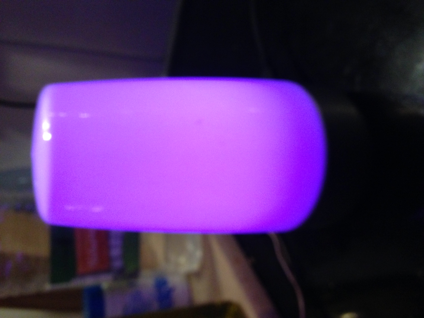
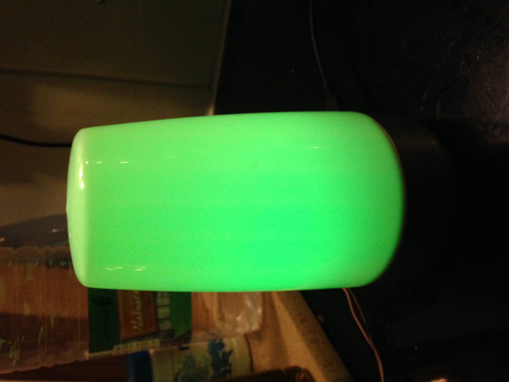
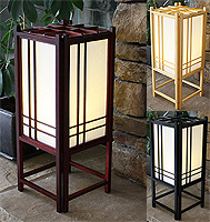
    After playing around with my first Arduino, a couple of years ago, I knew I wanted to use it to create a Gesture controlled Japanese Floor lamp. Like one on this picture.
    alt text

    At the time I knew little to nothing about how to design the schematics or how I'd would be able to hook that lamp in to a Home Automation system. Hence I didn't even know what a Home Automation was at the time. Well luckily thanx to MySensors I don't need to know it. I just have to hookup an antenna, and add the correct code into my sketch.

    So that problem was tackled. I think it was about a year ago, that I came across this little gesture sensor. It's sparkfun's APDS-9960. It's a rather expensive sensor used in the Samsung galaxy S5. Now I know that there are cheaper alternatives, but at the time I bought one and it ended up in one of my desk drawers.

    Since I can't do my woodworking during winters, I design the electronics I use in my woodworking projects in the winter. And embed them in my woodworking projects when the temperature is high enough. When I begin thinking about the woodworking projects I want to build this woodworking season, I remembered the little gesture sensor.

    So much for the intro. But if you're still reading, you're probably interested in the real deal. I had a hard time using the APDS-9960. So it took me a lot of hours the get it to work. But I'll share my workarounds with you. The MySensors community has done a lot for me, so I think it's about time to do something back.

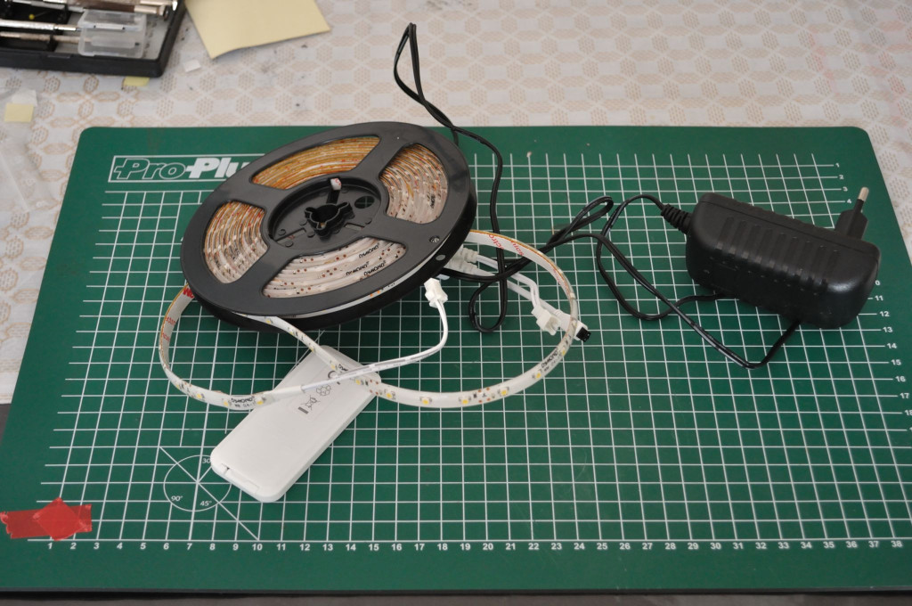
    I started with adjusting the cheap white strip I specially bought for this project. It contained a 5 meter white LED strip, a power adapter and some reusable parts.

    alt text

    The tine plastic housing can easily be opened with a small screw driver.

    alt text

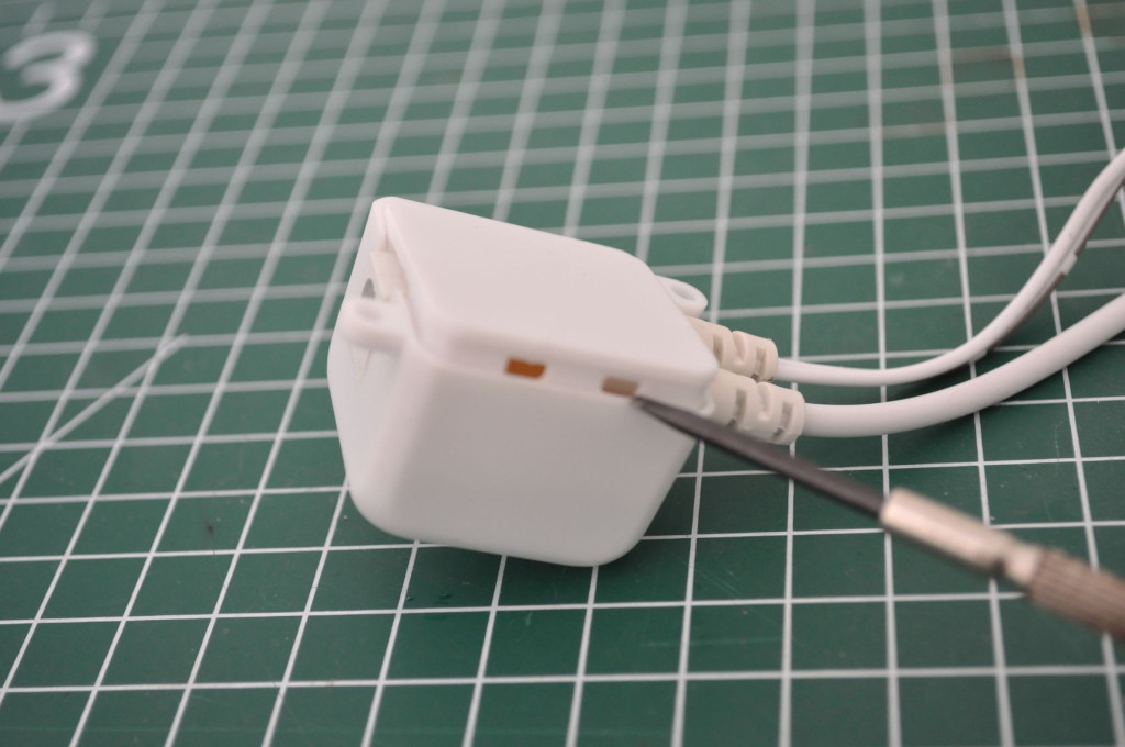
    And now I have acces to some goodies (IR receiver - allways useful, the power plug I'll be using in the final product, and a connector for connecting the LED strip ;-))

    alt text

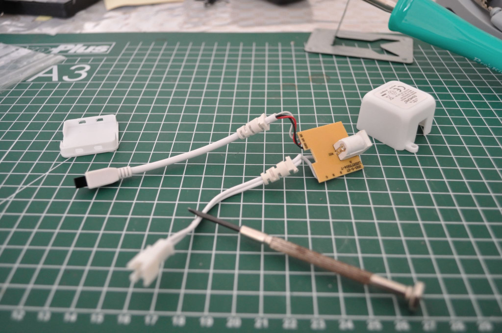
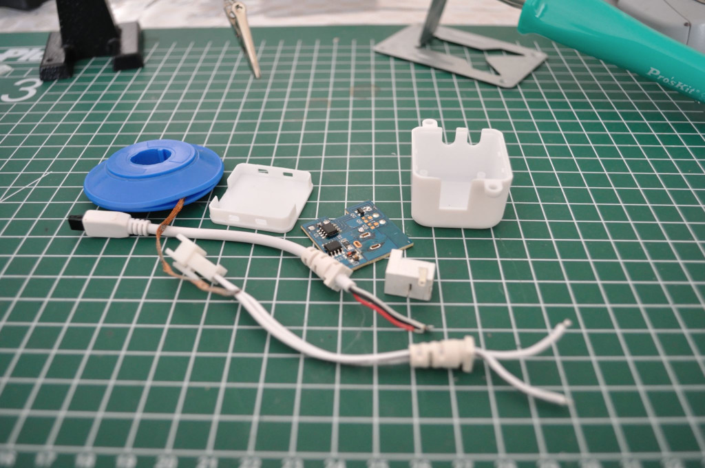
    It took a just a couple of minutes to desolder all the parts.
    alt text

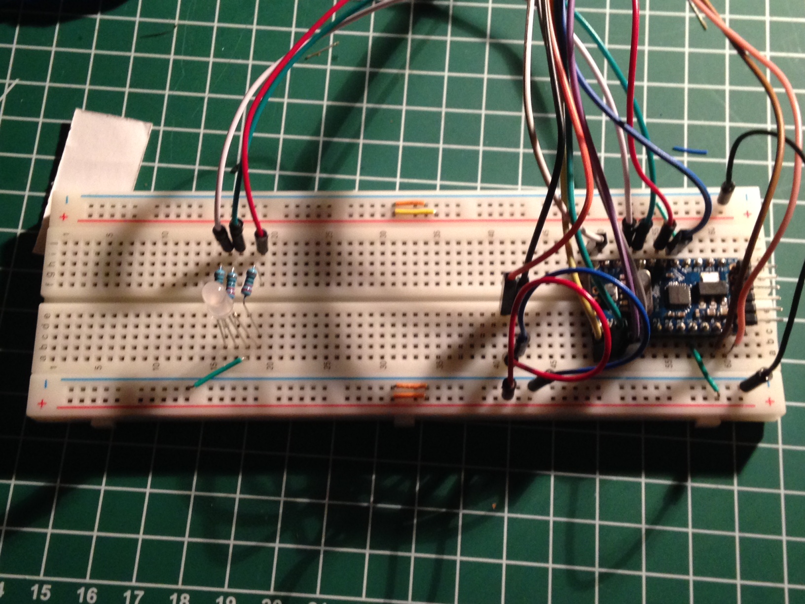
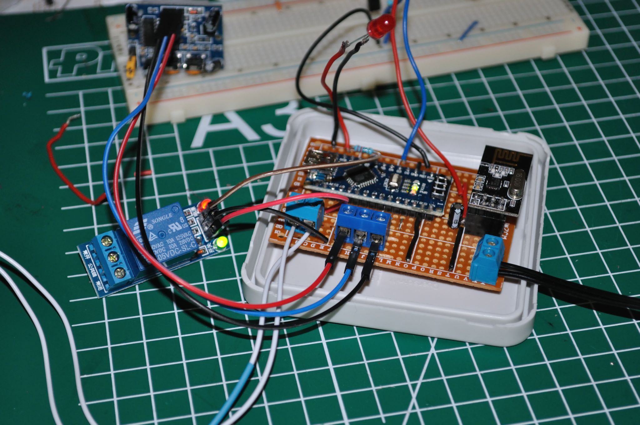
    And the complete circuit looks like this on my breadboard (small note the 7805CV is not mounted on this picture. I'm using two power adapters during development. One 5V for powering the Arduino circuit and one 12V for powering the LED strip).

    alt text

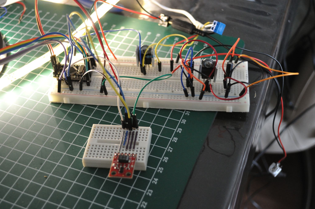
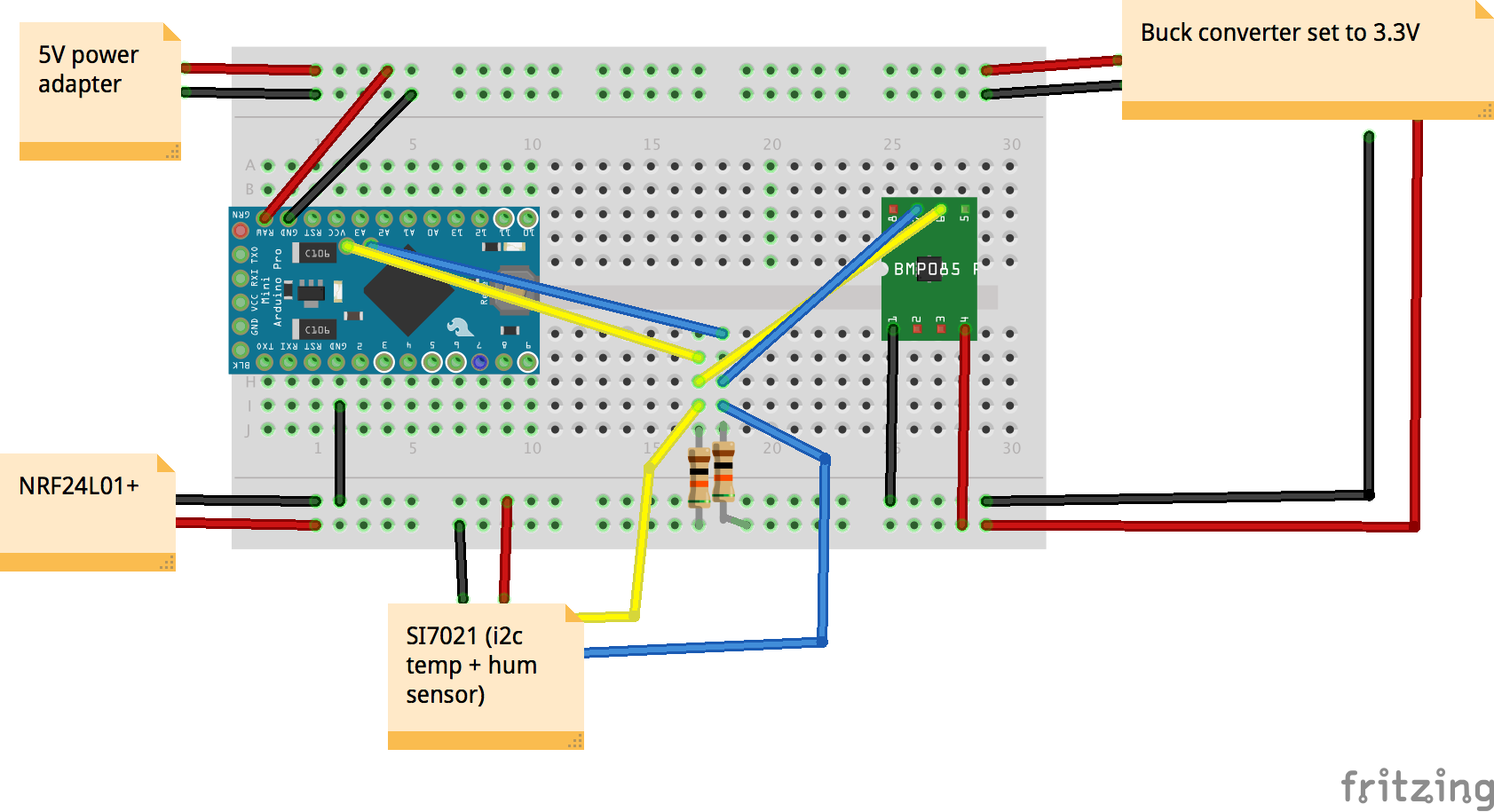
    Since most project descriptions don't go in much details about the schematics, some of them are just out of my league. That's why I decided to add everything in this post. This project was really complex for me, because the circuit uses 12V, 5V and 3.3V. But besides for the part that I don't think that I use the right capacitors (it works though) the completed circuit looks like this.

    Circuit

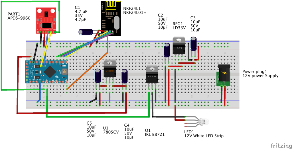
    There are a couple of things I want to point out. According to Sparkfun the Pro Mini 3.3V can be fed with 12V. But I blew up my raw pin during the design that's why I added the 7805CV power regulator. I'm using a Wite LED strip, which came with a 12V 1500 milli amp power adapter. At the moment I'm able to use that adapter for feeding both the Arduino circuit and the LED strip. But the adapter gets warm. For me that's okay. I'll be using one meter of the 5 meter led strip at the most. So I'm pretty confident that the original power adapter will provide enough amperage for the complete circuit.

    I've measured the usage of the arduino circuit and it uses about 380 milli amps. Which is stable until the circuit communicates with the gateway - sending new brightness level to the gateway. At that point the circuits absorbs about above 500 milli amp. Again measured without the LED strip consumption.

    I use an N channel Mosfet for controlling the LED strip. That is necessary because LED strips share a common anode. This regarding to most RGB Led's that share a common cathode. (But I'm not an electronics specialist so correct me if I'm wrong.)

    Here's the shopping list:
    Amount Part Type
    1 Electrolytic Capacitor 35V; 4.7µF;
    4 Electrolytic Capacitor 50V; 10µF;
    1 12V White LED strip with power Adapter ( you can use an RGB led strip, but you'll be needing 2 extra MOSFETS in that case)
    1 NRF24L01+
    1 Pro Mini 3.3V (You can use Pro Mini 5V, but you'll have to use a logical level converter, the APDS can only handle 3.3V)
    1 APDS-9960 RGB (you can use the cheaper APSD-9930 you can find on e-bay, but you'll need an altered library!)
    1 Power plug (I salvaged mine from the, from the LED strip package I bought)
    1 IRL B8721 N-channel mosfet (when using a short piece of led strip, a 2N2222 might do. But I had this one lying around and it's able to control high amperage (6 Amp if I'm not mistaken)
    1 LD33 Low-Dropout Voltage Regulator
    1 7805CV Voltage Regulator - 5V (other types of 7805 might do, but I have this ones on spare)

    For the Sketch you'll be needing the Spark fun APDS-9960 library. It can be downloaded here. It's not the best library I've ever used though. But I couldn't find another one.

    After you've hooked up all the electronics the real fun starts (we'll actually it doesn't, playing with the final project is even more fun). One note. The original author of Spark fun, probably had a less sensitive sensor than the one I have. After a long search I've found the solution to get my sensor the work which is:

        apds.setGestureGain( 1 );
    

    You might need to change that value to your sensor. Valid values can be found in the library, but for convenience they are in the range of 0-3. 0 is very sensitive and 3 is less sensitive.

    The lamp can be controlled from your Home Automation system, as well with gestures. The gestures are:

    • Left swipe turns the lamp off
    • Right swipe turns the lamp on
    • Up swipe raises brightness. If the brightness is already at the max it will indicate this by turning the lamp of for a short moment and back on again.
    • Down swipe lowers the brightness. If the brightness can't be lowered it'll turn the lamp off.

    You can use the gesture sensor in a stand alone sketch as well. After playing with the gesture controlled Lamp I've discovered some use cases in which a gesture controlled lamp or switch is really handy:

    1. Controlling lights under kitchen cabinets. When preparing a meal it's not hygienic to turn on/off a normal switch. With a gesture controlled switch you don't have to touch the switch.
    2. Mount one in your workshop. When working on your car or motor cycle, it'll be certain that you get grease or oil on your hands. When needing light you don't have to touch the switch just use a gesture and you can turn on or off your lighting. That way you don't have to clean the switch after you're done working on your car or whatever it is you are working on.

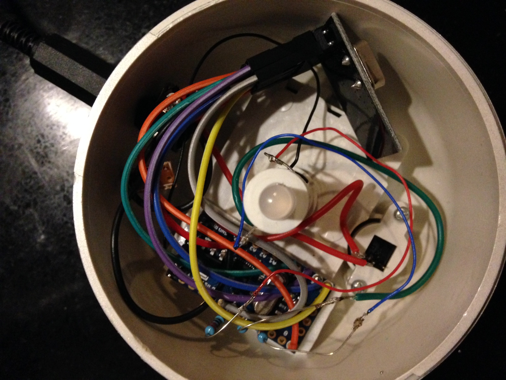
    If you've reached this point. My appologies for this long post. Thank you that you've found it worth reading. I'll post a follow up after the Japanse Lamp is finished - incl. the mounting of the electronics.

    Here's the Sketch.

    /****************************************************************
      Gesture controlled lamp
      MySensors enabled, gesture controlled lamp.
      
      March 2016 by Theo
      
      This lamp can be turned on/off, and dimmed by gestures. And it can be controlled by any Home Automation
      system, that can talk with MySensors.
      
      The gesture sensor used in this Sketch is an APDS-9960 RGB and Gesture Sensor, sold by SparkFun.
    
      This Sketch is based upon the GestureTest exampl developped by,
      Shawn Hymel @ SparkFun Electronics on May 30, 2014. See https://github.com/sparkfun/APDS-9960_RGB_and_Gesture_Sensor
    
      Hardware Connections (APDS-9960):
      IMPORTANT: The APDS-9960 can only accept 3.3V!
     
       Arduino Pin  APDS-9960 Board  Function
     
       3.3V         VCC              Power
       GND          GND              Ground
       A4           SDA              I2C Data
       A5           SCL              I2C Clock
       2            INT              Interrupt
    
      The lamp itself is a white LED strip, controlled by an N channel MOSFET.
    ****************************************************************/
    #include <SPI.h>
    #include <MySensor.h>  
    #include <Wire.h>
    #include <SparkFun_APDS9960.h>
    
    // Pins
    #define APDS9960_INT                      2   // Needs to be an interrupt pin
    #define LED_PIN                           3   // The led PWM pin, that drives the LED strip
    #define MAXDIMLEVELS                     100  // The maximum number of dim levels
    #define BRIGHTNESS_INCREMENT             15   // Dimmer increment for gesture(s)
    #define MAX_LEVEL_REACHED_DELAY          150  // Short blinking delay when increasing the dimmer while the dimmer is already at max
    #define MAX_LEVEL_REACHED_SIGNAL_COUNT   1    // The amount of blinks, when the max dim level already has been reached
    #define CHILD_ID_LIGHT                   1    // The child id of the Node. Only one Node on this sensor though.
    #define LIGHT_OFF                        0    // Constant indicating the lamp on state
    #define LIGHT_ON                         1    // cConstant indicationg light off state
    #define SN "Gesture controlled lamp" // Description of this sketch. 
    #define SV                               "1.1" // The version of the Sketch
    
    
    // Global Variables
    SparkFun_APDS9960 apds = SparkFun_APDS9960();
    int isr_flag = 0;                // interrupt flag, triggered when a gesture has been dectected
    
    int LastLightState=LIGHT_OFF;
    int LastDimValue=100;
    
    int dimlevels[ MAXDIMLEVELS ] =  // PWM values used for translating home automation dimmer levels. This gives smoother transations
      {   0,   1,   2,   3,   4,   5,   6,   7,   8,   9,
         10,  11,  12,  13,  14,  15,  16,  17,  18,  19,
         20,  21,  22,  23,  24,  25,  26,  27,  28,  29,
         30,  31,  32,  35,  39,  42,  46,  49,  52,  56,
         59,  62,  66,  69,  73,  76,  79,  83,  86,  89,
         93,  96, 100, 103, 106, 110, 113, 116, 120, 123,
        126, 130, 133, 137, 140, 144, 147, 150, 154, 157,
        160, 164, 167, 171, 174, 177, 181, 184, 187, 191,
        194, 197, 201, 204, 208, 211, 215, 218, 221, 225,
        228, 231, 235, 238, 242, 245, 246, 250, 251, 255 };
    
    MySensor gw;
    MyMessage lightMsg(CHILD_ID_LIGHT, V_LIGHT);
    MyMessage dimmerMsg(CHILD_ID_LIGHT, V_DIMMER);
    
    void setup() {
      gw.begin(incomingMessage, AUTO, false);
    
      // Send the Sketch Version Information to the Gateway
      gw.sendSketchInfo(SN, SV);
    
      gw.present(CHILD_ID_LIGHT, S_DIMMER, "floor lamp", true );
      
      // declare output pin for PWM control of the MOSFET
      pinMode( LED_PIN, OUTPUT );
      
      // Set interrupt pin as input
      pinMode(APDS9960_INT, INPUT);
      
      // Initialize interrupt service routine
      attachInterrupt(0, interruptRoutine, FALLING);
    
      // Initialize APDS-9960 (configure I2C and initial values)
      if ( apds.init() ) {
        // original value is two. But it looks like the modern gesture sensor or more sensitive. 1 does it for me
        apds.setGestureGain( 1 );
      }
      
      // Start running the APDS-9960 gesture sensor engine
      if ( apds.enableGestureSensor(true) ) {
        LastLightState=LIGHT_OFF;
        LastDimValue=0;
        analogWrite( LED_PIN, 0 );
        gw.request( CHILD_ID_LIGHT, V_PERCENTAGE );
        gw.request( CHILD_ID_LIGHT, V_STATUS );
      }
      //Here you actualy switch on/off the light with the last known dim level
    }
    
    // The Sketh's main loop
    void loop() {
      if( isr_flag == 1 ) {
        detachInterrupt(0);
        handleGesture();
        isr_flag = 0;
        attachInterrupt(0, interruptRoutine, FALLING);
      }
      gw.process();
    }
    
    // interrupt handler. Is being traggerd by the gesture sensor whenever a gesture has been detected.
    void interruptRoutine() {
      isr_flag = 1;
    }
    
    // Determine gesture and handle accordingly.
    void handleGesture() {
      if ( apds.isGestureAvailable() ) {
        switch ( apds.readGesture() ) {
          case DIR_UP:
            if ( LastDimValue + BRIGHTNESS_INCREMENT > ( MAXDIMLEVELS - 1 ) ) {
              for ( int i = 0; i < MAX_LEVEL_REACHED_SIGNAL_COUNT; i++ ) {
                analogWrite( LED_PIN, dimlevels[ 0 ] );
                gw.wait( MAX_LEVEL_REACHED_DELAY );
                analogWrite( LED_PIN, dimlevels[ MAXDIMLEVELS - 1 ] );
                gw.wait(MAX_LEVEL_REACHED_DELAY );
              }
              LastDimValue = ( MAXDIMLEVELS - 1 );
            }
            else {
               LastDimValue += BRIGHTNESS_INCREMENT;
            }
            LastLightState = LIGHT_ON;
            SetCurrentState2Hardware();
            break;
          case DIR_DOWN:
            if ( LastDimValue - BRIGHTNESS_INCREMENT <= 0 ) {
              LastDimValue = 0;
            }
            else {
               LastDimValue -= BRIGHTNESS_INCREMENT;
            }
            if ( LastDimValue == 0 ) {
              LastLightState = LIGHT_OFF;
            }
            else {
              LastLightState = LIGHT_ON;
            }
            SetCurrentState2Hardware();
            break;
          case DIR_LEFT:
            LastLightState = LIGHT_OFF;
            SetCurrentState2Hardware();
            break;
          case DIR_RIGHT:
            LastLightState = LIGHT_ON;
            SetCurrentState2Hardware();
            break;
        }
      }
    }
    
    void incomingMessage(const MyMessage &message) {
      if (message.type == V_LIGHT) {
        int lstate= atoi( message.data );
        if ((lstate<0)||(lstate>1)) {
          return;
        }
        LastLightState=lstate;
        if ((LastLightState==LIGHT_ON)&&(LastDimValue==0)) {
           //In the case that the Light State = On, but the dimmer value is zero,
           //then something (probably the controller) did something wrong,
           //for the Dim value to 100%
          LastDimValue=100;
        }
        
        //When receiving a V_LIGHT command we switch the light between OFF and the last received dimmer value
        //This means if you previously set the lights dimmer value to 50%, and turn the light ON
        //it will do so at 50%
      }
      else if (message.type == V_DIMMER) {
        int dimvalue= atoi( message.data );
        if ((dimvalue<0)||(dimvalue>100)) {
          return;
        }
        if (dimvalue==0) {
          LastLightState=LIGHT_OFF;
        }
        else {
          LastLightState=LIGHT_ON;
          LastDimValue=dimvalue;
        }
      }
    
      //Here you set the actual light state/level
      SetCurrentState2Hardware();
    }
    
    void SetCurrentState2Hardware() {
      if (LastLightState==LIGHT_OFF) {
         analogWrite( LED_PIN, dimlevels[0] );
      }
      else {
         analogWrite( LED_PIN, dimlevels[ LastDimValue - 1 ] );
      }
    
      //Send current state to the controller
      SendCurrentState2Controller();
    }
    
    void SendCurrentState2Controller()
    {
      if ((LastLightState==LIGHT_OFF)||(LastDimValue==0)) {
        gw.send(dimmerMsg.set(0));
      }
      else {
        gw.send(dimmerMsg.set(LastDimValue));
      }
    }
    
    My Project

  • Free MySensors 2.0 workshop, Friday 9 September in Amersfoort (The Netherlands)
    TheoLT TheoL

    I’m organizing an entry-level MySensors 2.0 workshop/ master class for those who would like to kick-start in creating MySensors 2.0 based nodes and have little experience in electronics. The workshop will be held on Friday the 9th of September as a side track during Trivento’s annual Summercamp. The theme of this year’s Summercamp is Fast Data and let’s be honest: What is Fast Data without IoT?

    During this 3 hour workshop/ master class you’ll learn:

    • How the MySensors eco-system works and which role a gateway plays in the eco-system.
    • How to connect simple electronic components to an Arduino
    • The difference between AC and DC and why this is important when you connect electronics that have a polarity. (This is just enough to give you a kick-start, because we can not go deeply into electronics during a 3 hour workshop).
    • The anatomy of a sketch for a MySensors node.
    • How to create some simple MySensors nodes (temperature sensor/ light sensor/ RGB light).
    • How you can combine multiple sensors into one node. We’ll be making a temperature/ light level node.
    • Get an overview of the different gateways that are supported by MySensors.
    • How you can secure your nodes by adding signing (and why everyone should do that).

    In order for you to be able to participate you need have some basic knowledge of writing software. Because we unfortunately don't have time during this event to learn you how to write your software.

    If you don't live in the Netherlands, but just happen to be in the neighborhood. The language for the Summercamp and workshop is all English and we're happy to welcome you.

    So if you want to learn about MySensors, want to have some fun and maybe drink a beer after the workshop please don’t hesitate to register for this fun event. This is a BYOL event, which means that you’ll bring your laptop and I’ll provide the Arduinos and the other electronic components you’ll need.

    There’s no fee for participating in this workshop. However, there is a limited number of places available, so please register as soon as possible if you want to participate.

    Finally, the keynote for the Summercamp is also worth mentioning. This will be ‘Challenges and opportunities around elastic data pipelines’ by Jorg Schad, (Distributed Systems Engineer at Mesosphere, Inc.).

    General Discussion

  • MySensorfying a cheap moodlight
    TheoLT TheoL

    It might be just me, but since I discovered my Sensors, I look at the world differently. I want to put MySensors in everything. So last week I came across some cheap mood-lights in a shop. They're 3 euro's a piece. Before I bought them I checked if they can be opened easy and that was the case.

    The mood-light is a 3 AAA powered diffused 5mm LED with one resistor. The diffused LED only has to pens and in it is an IC that loops through a mood-light program. But I couldn't use the LED, because in the future I want to control the mood-light as an RGB lamp as well. So I stripped the electronics out of the mood-light to see if there's enough space to put in a Arduino Pro Mini 3.3V and a Antenna. It looked like it would fit.

    I ordered a couple Pro Mini 3.3V and ordered a couple of diffused 5mm RGB leds. I put everything on a breadboard and developed a sketch.
    image1.JPG

    I had a hard time finding a good Mood-light example. Most of the examples on instructables.com didn't have a smooth transition between the different colors. But luckily I found a good library called MoodLight by Kasper Kamperman. You can download the library from his blog http://www.kasperkamperman.com/blog/arduino-moodlight-library/

    The first version implements only a Mood-light. I tried to add the S_RGB but my Domoticz version doesn't support it. So I will put that in the sketch as well. I plan to use that light as a mood-light, but also as warning lamp. E.g. if someone is comming to my front door it will show a green color.

    /**
     * MySensors Moodlight
     * Version 1.0
     * created September 22nd 2015
     * by Theo
     *
     * Change log:
     * 27-09-2015 Stable version released after a couple days of testing.
     * 
     * Description:
     *   Sketch for creating a cheap MySensors controlled MoodLight which also can be controlled as an dimmable RGB light.
     *
     * Future plans:
     * - enable it as an RGB lamp as well. Have to wait until Domoticz supports it. Which will probably be in the next stable version.
     *
     * Dependencies:
     *   MoodLight.h
     *
     * Hardware used:
     *   Arduino Pro Mini 3.3V
     *   Difused 5mm RGB led
     *   LR2401 Antenna
     *   one 4.7Uf capacitor
     *   three 220 Ohm resistors, to prevent the RGB led from burning out, but might be lower because we're feeding it only 3.3V instead of 5V
     *   A really cheap 3 AAA battery powered moodLight (found it in a store for around 3 euros)
     * 
     * Total costs without the regulator circuit (also adapter not included, used an old phone power adapter)
     *   Arduino 6.00 euro
     *   RGB led 0.60 euro
     *   antenna 2.00 euro
     *   4.7 uF  0.30 euro
     *   resistors 0.00 euro had them laying around doing nothing
     *   moodlight housing 3.00 euro
     *   wires and solder etc. 0.00 euro had that laying around ass well
     *   
     * Sums up to 11.90 euro add 2 euro to it for wires etc and it's still below 15 euro. Nice!!! ;-)
     */
    
    /**
     * Include libraries.
     */
    #include <MoodLight.h>  // great library for moodlight implementations.
    #include <SPI.h>        // needed for the Antenna
    #include <MySensor.h>   // include the real magic.
     
    /**
     * declare Pins used by the sketch. Use #define because that the compiler will replace it so it saves a bit of memory
     */
    #define REDPIN 3              // pwm pin with red led (Only use a PWM that is not being occupied by the antenna)
    #define GREENPIN 5            // pwm pin with green led (Only use a PWM that is not being occupied by the antenna)
    #define BLUEPIN 6             // pwm pin with blue led (Only use a PWM that is not being occupied by the antenna)
    #define MOODLIGHTDELAY 175    // the amount of time a particular moodlight value is being shown before the next one will be shown
    #define SATURATION 255        // use value between 0 - 255 <--- This is a candidate to remove
    #define BRIGHTNESS 255        // use value between 0 - 255 <--- This is a candidate to remove
    #define MLHUEUPPERLEVEL 359   // The higher bound of the ml's hue factor
    #define SN "Moodlight"        // Define the Sketch's name
    #define SV "1.0"              // Define the sketch's version 
    #define CHILD_ID_MOODLIGHT 0  // Define the child ID of the moodlight
    
    /**
     * Declare new data types, enum etc
     */
    // Light program modes
    enum LIGHTMODE {
      LIGHTOFF = 0,
      MOODLIGHT = 1,
      RGBVALUE = 2   // reserved for future useage
    };
    
    /**
     * Declare global variables (haven't looked into what saturation and brightness will do for the moodlight)
     */
    int hue = 0; // use value between 0 - 359
    MoodLight ml = MoodLight(); // create MoodLight object
    int currentLightMode = LIGHTOFF;
    long RGB_values[3] = {0,0,0};
    
    MySensor gw;
    MyMessage lightMsg( CHILD_ID_MOODLIGHT, V_LIGHT);
    
    /**
     * Initialize Sketch. Declare pins and MySensors etc.
     */
    void setup() {
      // Serial.begin( 115200 );
      // Setup PWM pins for output
      pinMode( REDPIN, OUTPUT );
      pinMode( GREENPIN, OUTPUT );  
      pinMode( BLUEPIN, OUTPUT ); 
    
       // initialize ml for first time display.
       ml.setHSB(hue, SATURATION , BRIGHTNESS );
     
      // Initialize mySensor gateway
      gw.begin( incomingMessage );
      gw.sendSketchInfo(SN, SV);  
    
      // Register the LED Dimmable Light with the gateway
      gw.present( CHILD_ID_MOODLIGHT, S_LIGHT );
      // It just me being neurotic, but inform controller that power level is 100%
      gw.sendBatteryLevel( 100 );
    
      // Request the current Moodlight status from the controller.
      gw.request( CHILD_ID_MOODLIGHT, V_LIGHT );
    }
    
    /*
     * Calculate red, green, blue values based upon current hue, saturation and brightness.
     * Display the new values and adjust the hue to the next step.
     */
    void setAndShowNextMoodlightValue() {
      // assign current values to the ml object
      ml.setHSB( hue, SATURATION, BRIGHTNESS );
    
      // read the Red, Green and Blue values and assign them to the led pins
      analogWrite( REDPIN, ml.getRed() );
      analogWrite( GREENPIN, ml.getGreen() );
      analogWrite( BLUEPIN, ml.getBlue() );
      
      hue++; // set the next moodlight step
      if ( hue > MLHUEUPPERLEVEL ) { // adjust if we've reached the upperlevel
        hue = 0;
      } 
    }
    
    /**
     * Main loop of the Sketch
     */
    void loop() {
      if ( currentLightMode == MOODLIGHT ) {
        setAndShowNextMoodlightValue();
      }
      gw.wait( MOODLIGHTDELAY ); 
    }
    
    /**
     * Callback function for handling messages received from the gateway.
     */
    void incomingMessage(const MyMessage &message) {
      if ( message.sensor == CHILD_ID_MOODLIGHT && message.type == V_LIGHT ) { // received a Light Status from the gateway
        currentLightMode = message.getBool() == 1 ? MOODLIGHT : LIGHTOFF;
        // adjust the RGB led to the (new) light state
        if ( currentLightMode == MOODLIGHT ) { 
          analogWrite( REDPIN, ml.getRed() );
          analogWrite( GREENPIN, ml.getGreen() );
          analogWrite( BLUEPIN, ml.getBlue() );
        }
        else {
          analogWrite( REDPIN, 0 );
          analogWrite( GREENPIN, 0 );
          analogWrite( BLUEPIN, 0 );
        }    
      }
    }
    

    So after playing with the mood-light on the breadboard for a couple of days. Just to see if it's stable. I finally found some time to solder the Arduino and the Antenna and mount everything in the mood-light.

    I cut some dupont cables in half and soldered them directly on the proMini. I was lucky that I had the same colors as used in the connecting the radio article on the mysensor build site. So it'll be very easy to replace the radio when needed. There's also a 4,7 uf cap that I stuck directly in the VCC and ground pins of the dupont cables.

    It was really hard to mount the electronics in the light, because you have all most no working space. But I managed to do it.
    image2.JPG

    Also I soldered the 220 ohm resistors directly on the ProMini and soldered the LED wires to the resistor. I used double sided carpenters tape to stick the arduino on the lamp. Double sided tape is really strong. I use it to put my templates on wood, if I want to route a pattern in the wood. Believe me it's strong.

    So here are some photo's of the mood-light in action.
    image3.JPG

    image4.JPG

    Sorry I wasn't able to rotate the photo's. The circuit is really easy. I power the NRF24L01 directly from the ProMini 3.3V. Each pin that is connected to the RGB led, connects through a 220Ohm resistor. I used pins 3, 5 and 6 to control the LED, because they're PWM pins.

    I'll have to learn Fritzing. I've been playing with it, but I couldn't find the NRF24L01 component.

    My Project

  • Library for thresholded readings of sensors
    TheoLT TheoL

    Since this is not really a hardware project, Ive decided to post this just on the forum.

    I bought the Sense Bender a couple of months ago. I'm not only happy with the Sense Bender itself, but also by the example Sketch. It changed the way I'm thinking about sending sensor values to the gateway. There's absolutely no need to send the values immediately when the change. I really love the threshold way of sending values.

    For those of you who don't know the Sense Bender sketch. It sends the temp and humidity values only every 5 minutes or if their values have changed a threshold value after the last value send. To simplify things for my self and to be able to reuse it, I've created a library for this. It really makes the sketch part easy. You just register the sensors, add some callback functions, call the check threshold method in the loop and the library will:

    • ask for a sensor's value when it needs it;
    • tell you when you need to send a value to the library.

    Here's the sketch I've created today. It combines a Si7021 Temp + humidity sensor, a BMP180 pressure sensor and a cheap photo diode LM393 light level sensor. And only reports their values by using the ThresholdUtil library. It makes creating thresholded sensor nodes so easy, that I'm happy to share it with everyone.

    Note: I'm testing this library right now. It looks bug free. So I've released it as a buy me a beer if you happen to meet me and like this library. Or throw it away if you don't like it.

    /**
       Room conditions node. Measure temperature, humidity, lightlevel and pressure.
    
       Copyright (c) ByTheo
    
       Description:
       This Node demonstrates the useage of the ThresholdUtil library, by combining a temperature, humidity, lightlevel and barometric sensors
       It also utilizes the Forecast algorithm from the MySensors build page, which for this purpose has been put in a separate library
    
       Developped on a ProMini 3.3V. Sensors used:
       - BMP180 Pressure sensor (can also read temperature but not used by this Node)
       - SI7021 Humidity and temperature sensor
       - Photo Diode LM393 sensor (bought an Aliexpress
    
       History
         August 20th 2016 - Initial version
    
       This program is free software; you can redistribute it and/or
       modify it under the terms of the GNU General Public License
       version 2 as published by the Free Software Foundation.
    
     *******************************
    */
    
    #include <SPI.h>
    #include <MySensor.h>
    #include <Wire.h>
    #include <SI7021.h>
    #include <Adafruit_BMP085.h>
    #include "ThresholdUtil.h"
    #include "WeatherForecast.h"
    
    // Uncomment when debugging
    // #define RC_DEBUG
    
    // Define Arduino Pins used by sensors A4 and A5 are also used for i2c bus
    #define LIGHT_SENSOR_ANALOG_PIN A0
    #define LIGHT_SENSOR_DIGITAL_PIN 3
    
    // The altitude of the location where the sensor is being placed. Adjust to your location
    #define ALTITUDE 33.0
    
    // Define constants for children used by Node
    #define TEMPEARTURE_SENSOR_CHILD_ID  0
    #define HUMIDITY_SENSOR_CHILD_ID     1
    #define LIGHTLEVEL_SENSOR_CHILD_ID   2
    #define PRESSURE_SENSOR_CHILD_ID     3
    
    // Declare Sensor ID's used for ThresholdUtil library
    #define TEMPEARTURE_SENSOR_ID 1
    #define HUMIDITY_SENSOR_ID    2
    #define LIGHTLEVEL_SENSOR_ID  3
    #define PRESSURE_SENSOR_ID    4
    
    // Declare Sketch Name and Version
    #define MYS_SKETCH_NAME "Improved room conditions"
    #define MYS_SKETCH_VERSION "1.0"
    
    // Variabe used for remembering lastForeCast send to the gateway
    int lastForecast = -1;
    
    // Create objecs for i2c sensors
    Adafruit_BMP085 bmp = Adafruit_BMP085();
    SI7021 sensor;
    
    // Declare MySensors class and messages
    MySensor gw;
    MyMessage tempMsg( TEMPEARTURE_SENSOR_CHILD_ID, V_TEMP );
    MyMessage pressureMsg( PRESSURE_SENSOR_CHILD_ID, V_PRESSURE);
    MyMessage forecastMsg( PRESSURE_SENSOR_CHILD_ID, V_FORECAST);
    MyMessage msgHum(HUMIDITY_SENSOR_CHILD_ID, V_HUM);
    MyMessage lightLevelMsg(LIGHTLEVEL_SENSOR_CHILD_ID, V_LIGHT_LEVEL);
    
    /**
     * Setup method. This will initialize the i2c sensors, register Thresholds. Initializes MySensors and presents the children of the node. Finally the initial values are being send
     * to the gateway
     */
    void setup() {
    #ifdef RC_DEBUG
      Serial.begin( 115200 );
    #endif
      // initialize I2C sensors
      sensor.begin();
      bmp.begin();
    
      // register sensors and their thresholds
      registerThresholdedSensor( TEMPEARTURE_SENSOR_CHILD_ID, TEMPEARTURE_SENSOR_ID, TEMPERATURE_SENSOR, 0.5,  5, 60  ); // read every 5 sec and report at least every 5 minute
      registerThresholdedSensor( HUMIDITY_SENSOR_CHILD_ID,    HUMIDITY_SENSOR_ID,    HUMIDTY_SENSOR,     1.0, 10, 30  ); // read every 5 sec and report at least every 5 minute
      registerThresholdedSensor( LIGHTLEVEL_SENSOR_CHILD_ID,  LIGHTLEVEL_SENSOR_ID,  LIGHTLEVEL_SENSOR,  2.0,  1, 300 ); // read every 5 sec and report at least every 5 minute
      registerThresholdedSensor( PRESSURE_SENSOR_CHILD_ID,    PRESSURE_SENSOR_ID,    PRESSURE_SENSOR,    0.5, 60, 10  ); // every minute. report at least every 10. Forecast algorithm wants new value every minute
    
      // Register the node to the gateway
      gw.begin();
    
      // Send the sketch version information to the gateway and Controller
      gw.sendSketchInfo( MYS_SKETCH_NAME, MYS_SKETCH_VERSION );
      gw.wait( 50 ); // give radio the time to register the child
    
      gw.sendBatteryLevel( 100, true );
      gw.wait( 50 ); // give radio the time to register the child
    
      // Register sensors to gw (they will be created as child devices)
      gw.present( PRESSURE_SENSOR_CHILD_ID, S_BARO, "Barometer", true );
      gw.wait( 50 ); // give radio the time to register the child
      gw.present( TEMPEARTURE_SENSOR_CHILD_ID, S_TEMP, "Temperature", true );
      gw.wait( 50 ); // give radio the time to register the child
      gw.present( HUMIDITY_SENSOR_CHILD_ID, S_HUM, "Humidity", true );
      gw.wait( 50 ); // give radio the time to register the child
      gw.present( LIGHTLEVEL_SENSOR_CHILD_ID, S_LIGHT_LEVEL, "Light level", true );
      gw.wait( 50 ); // give radio the time to register the child
    
      checkThresholdedSensors( readSensorValue, reportSensorValue ); // Send initial values to the gateway
    }
    
    /*
     * Call back method for ThresholdUtil library, will ask for sensor values when the library needs them
     * 
     * ps. don't forget to put a * in front of the value inside the method. The library will not receive any
     * values if you forget the *
     */
    void readSensorValue( uint8_t aSensorId, ThreshHoldedSensorType aType, float *value ) {
      switch ( aSensorId ) {
        case TEMPEARTURE_SENSOR_ID:
          if ( aType == TEMPERATURE_SENSOR ) {
            *value = sensor.getCelsiusHundredths() / 100.0;
          }
          break;
        case HUMIDITY_SENSOR_ID:
          if ( aType == HUMIDTY_SENSOR ) {
            *value = sensor.getHumidityPercent() * 1.0;
          }
          break;
        case LIGHTLEVEL_SENSOR_ID:
          if ( aType == LIGHTLEVEL_SENSOR ) {
            *value = (float)( 1023 - analogRead( LIGHT_SENSOR_ANALOG_PIN ) ) / 10.23;
          }
          break;
        case PRESSURE_SENSOR_ID:
          if ( aType == PRESSURE_SENSOR ) {
            float pressure = bmp.readSealevelPressure( ALTITUDE ) / 100.0;
            *value = pressure;
            int forecast = sample( pressure );
            if (forecast != lastForecast) {
              gw.send( forecastMsg.set( weather[ forecast ] ), true );
              gw.wait( 50 );
              lastForecast = forecast;
    #ifdef RC_DEBUG
              Serial.print( "New forecast " ); Serial.println( forecast );
    #endif
            }
          }
          break;
      }
    }
    
    /**
     * Call back function being called by the thresholdUtil library whenever a threshold or forced transmit has been detected
     */
    void reportSensorValue( uint8_t child_id, uint8_t sensor_id, ThreshHoldedSensorType sensor_type, float value ) {
      switch ( child_id ) {
        case TEMPEARTURE_SENSOR_CHILD_ID:
    #ifdef RC_DEBUG
          Serial.print( "Temperature " ); Serial.print( value, 1 ); Serial.println( "C" );
    #endif
          gw.send(tempMsg.set(value, 1), true ); // Send temperature with 1 decimal precision
          break;
        case HUMIDITY_SENSOR_CHILD_ID:
    #ifdef RC_DEBUG
          Serial.print( "Humidity " ); Serial.print( value, 0 ); Serial.println( "%" );
    #endif
          gw.send(msgHum.set( value, 1 ), true ); // Send temperature with 1 decimal precision
          break;
        case LIGHTLEVEL_SENSOR_CHILD_ID:
    #ifdef RC_DEBUG
          Serial.print( "Light level " ); Serial.print( value, 0 ); Serial.println( "%" );
    #endif
          gw.send( lightLevelMsg.set( value, 0 ), true );
          break;
        case PRESSURE_SENSOR_CHILD_ID:
    #ifdef RC_DEBUG
          Serial.print( "Pressure " ); Serial.print( value, 1 ); Serial.println( " hPa" );
    #endif
          gw.send( pressureMsg.set( value, 0 ), true );
          break;
      }
      gw.wait( 50 );
    }
    
    /**
     * loop method. Basically we only call the checkTresholdedSensor method of the ThresholdUtil library
     */
    void loop() {
      checkThresholdedSensors( readSensorValue, reportSensorValue );
      gw.wait( 50 );
    }
    

    Here is the fritzing. I forgot the lightlevel sensor, but you can find how to wire it on the MySensors main page. For stability I power nothing from the Arduino. I use a Pro Mini 3.3V which I power with 5V from an adapter. I've used a cheap aliexpress buck converter and set it to 3.3V. That's my 3.3V power for the sensors and the radio.

    Fritzing

    Library and examples can be downloaded from my github ThresholdUtil.h For the code above you'll also need the WeatherForecast.h libraty, which is just the forecast algorithm from the MySensors build page that I've refactored to a separate .h file.

    My Project

  • 💬 Sensebender Gateway
    TheoLT TheoL

    It's has been a long time since I've posted on this forum.Today I received a note form the postal service that a package from a foreign country has arrived at my local postal office. Can't wait until tomorrow, just to see this beauty.

    Now I have to find some time to get it running ;-(

    OpenHardware.io mysensors gateway samd

  • Sensebender Micro
    TheoLT TheoL

    I just received two sensebenders. I'm really impressed by the great engineering behind the board. I can't wait to heat up my soldering iron. I love them!

    Announcements

  • Multimeter recommendation?
    TheoLT TheoL

    I volunteered to teach some of my colleagues how to create projects with an Arduino. The final lesson will be creating MySensors based projects. At the moment there are 20 people who assigned for my course. If only the half of them wants to continue creating MySensors and other cool projects, I have a group of people that'll br big enough to order things with discount. That's why I follow topics like this with much interest.

    General Discussion

  • Reinventing the motion controlled outside lamp
    TheoLT TheoL

    The former owners of my house installed a PIR sensors on my front door and the PIR motion controller is connected directlty to a lamp that's mounted next to my frontdoor. The thing that always bugged me, is that it turns on the light for the amount of minutes that it's set for. That causes the lamp to burn longer then necessary most of time, or that I have to wave my hand in front of the sensor whenever I'm talking to someone while standing in front of my door.

    This weekend I designed a new node that I'll be using instead of the current PIR motion sensor. I'm still thinking about how I can mount the PIR sensor in a waterproof housing. But the sensor works as follows:

    1. It will keep the light on for 20 seconds after the last movement has been detected. The PIR sensor has been set to smallest movement detection time, which is about 2 seconds. This knowledge is programmed into the sensor, because there was always a short amount of delay between motion detection and turning on the relay. This is an improvement on how a motion sensor normally functions. Which is an amount of time after the first motion detection I've tested it and the light is on when I need it and off when I don't need it.
    2. Whether the relay that's controlling the light has to be turned on when motion is detected, will be controlled by Domoticz. I have a different use case for this kind of sensor where I want to able to turn on the relay on only when I'm a sleep or not at home. A kind of surveillance light.
    3. A doorsensor - since I have enough pins and memory left, I might as well monitor when the door is opened and closed
    4. A DS18b20 sensor. This is also for future useage. For now I just measure the outside temperature. But I've not included this temp sensor in Domoticz.
    5. Each movement is reported to the Domotica controller.

    I'll add a Fritzing schema in a couple of days. I'm learning a lot about Fritzling lately. Here is how it looks on a PCB (not the best quality PCB). All used pin's can be looked up in the Sketch for now.

    Bewegingmelder_608.JPG

    Parts used:

    • Arduino Nano I power the relay and the PIR directly from the Nano's 5V output;
    • A NRF24L01+ radio powered directly from the 3.3v output of the nano
    • 4,7 uf capacitor for stabilizing the radio
    • PIR motion sensor
    • relay board
    • DS18B20 temperature sensor with a 4K7 Ohm resistor over VCC and data pin
    • a red 5mm led for motion indication, this will light up regardless of the fact that the relay has to be turned on or not.
    • 220 ohm resister between digital out and the VCC of the led

    I'll post a follow up of how I mounted this in a Waterproof box and how I mounted the PIR sensor in a waterproof housing.

    This is the Sketch:

    /**
     * Door, movement and temperature switch.
     *
     * This sensor has three main functions:
     * - A PIR Sensor for sensing movement around my front door. Each detected movement is being reported to the MySensors gateway.
     *   if the NIGHTMODE switch is on, it will also turn on the relay when a movement is being detected. (See design decisions)
     * - A door sensor for monitoring when the door of my little workshop is open or closed. Will use this in the future to trigger
     *   an alarm if the door is opened when we do not want it to be opened. E.g. when I'm a sleep at night.
     * - Since we've got some extra pins that are not in use, we might as well monitor the workshop's temperature.
     *
     * Created: September 26th 2015
     * Version: 1.1
     * Author:  by Theo
     * Website: http://www.houtbewerken-voor-dummies.com/domotica-beweging-in-je-tuin-meten
     *
     * Changelog:
     * 02-10-2015 - V1.1 Added function to leave the relay on for a while after the last detected movement.
     * 26-09-2015 - V1.0 initial version
     *
     * Design decision(s):
     * - Use a Dalas DS18b20 as a temperature sensor. It's much faster than a DHT11 or DHT22. We don't need a super accurate sensor, we're not
     *   going to control anything based upon the temperature in the Workshop.
     * - Add a dummy Light node for letting the PIR sensor controlling a relay. The switch needs to be turned on and off by the domotica controller
     *   when it's dark or not. In an earlier version I controlled the relay from my Domotica Controller, but I had a delay of about 1 second before the
     *   relay was switched on. Which was unacceptable to me. It would have been nice to read the delay value from Domoticz, but Domoticz doesn't allow  user variables for MySensors nodes. Vera does, but I don't have Vera so I can't test and develop it.
     */
    
    // Import the necessary libraries
    #include <MySensor.h>
    #include <SPI.h>
    #include <Bounce2.h>
    #include <DallasTemperature.h>
    #include <OneWire.h>
    
    // define constants. #define is more memory friendly than using static variables.
    #define TEMP_CHILD_ID 0
    #define MOTION_CHILD_ID 1
    #define SUNSET_CHILD_ID 2
    #define DOOR_CHILD_ID 3
    #define DOORSENSOR_PIN  4  // Arduino input pin for button/reed switch
    #define MOTIONSENSOR_PIN 5 // Arduino input pin for PIR motion sensor
    #define MOTIONLED_PIN 6    // Arduino output pun for visualization of detecting motion
    #define RELAY_PIN 7    // Arduino output pun for visualization of detecting motion
    #define ONE_WIRE_BUS 3     // Pin where dallas Ds18b20 sensor is connected
    #define TEMPERATURE_READING_INTERVAL 600000 // temperature reading interval in ms (min * 60000) in production we'll use 10 minutes
    #define LIGHTOFFDELAY 20000 // The amount of milliseconds the relay will be switched off after the last movement has been deteced (We'll use 20 seconds). Vera users can use a Vera variable for this. But I can not test this with Domoticz.
    
    // define sketch name and version
    #define SN "FrontdoorMotionDetection"
    #define SV "1.1"
    
    // Declare and initialize objects.
    MySensor gw;
    OneWire oneWire(ONE_WIRE_BUS); // Setup a oneWire instance to communicate with any OneWire devices (not just Maxim/Dallas temperature ICs)
    DallasTemperature dt_sensor(&oneWire); // Pass the oneWire reference to Dallas Temperature. 
    Bounce doorDebouncer = Bounce();   // declare a software debounce for debouncing the door reed relay switch 
    Bounce motionDebouncer = Bounce(); // declare a software debounce for debouncing the PIR motion sensor
    
    // declare and initialize global variables. Used to store old sensor and interval readings.
    int oldDoorSensorValue = -1;    // remember the door sensor's current state for detecting changes
    int oldMotionSensorValue = -1;  // remember the PIR motion sensor's current state for detecting changes
    float lastTemperature = 0.0;    // remember the temperature for detecting changes
    bool sunsetActive = false;      // state for indicating whether the relay has to be controllered by motion (domotica controller should set this to on after sunset and off after sunrise
    unsigned long previousMillis = 0; // interval variable for temperature sensor reading
    unsigned long scheduledRelayOffMillis = 0; // Scheduler for determining when the relay has to be switched off
    
    // Declare messages that will be sent to the MySensor's gateway.
    MyMessage doorMsg( DOOR_CHILD_ID, V_TRIPPED );
    MyMessage tempMsg( TEMP_CHILD_ID, V_TEMP );
    MyMessage motionMsg( MOTION_CHILD_ID, V_TRIPPED );
    
    // Initialization code for the sketch
    void setup() {  
    //  Serial.begin( 115200 ); // uncomment during debugging.
    
      // setup a connection to the MySensor's gateway and request an ID if we do not have one yet.
      gw.begin(incomingMessage);
      gw.sendSketchInfo(SN, SV);
      
      // Initialize Dalles temp sensor
      dt_sensor.begin();
      dt_sensor.setWaitForConversion( false );
      
      // initialize the door sensor so that the arduino can read it's value. And use internal 
      // pullup
      pinMode( DOORSENSOR_PIN, INPUT_PULLUP );
      // setup debouncer
      doorDebouncer.attach( DOORSENSOR_PIN );
      doorDebouncer.interval( 5 );
      
      // initialize PIR motion sensor
      pinMode( MOTIONSENSOR_PIN, INPUT_PULLUP );
      // setup debouncer
      motionDebouncer.attach( MOTIONSENSOR_PIN );
      motionDebouncer.interval( 5 );
      
      // initialize PIR visualization LED
      pinMode( MOTIONLED_PIN, OUTPUT );
      
      // initialize RELAY
      pinMode( RELAY_PIN, OUTPUT );
     //  Serial.println( "Testing relay" );
      // Testing relay just to let to knew everything is allright.. Used to test turnRelayOn and turnRelayOff method development. I liked it and kept it.
      for ( int i=0; i <3; i++ ) {
        turnOnRelay();
        gw.wait( 2000 );
    // delay(2000);
        turnOffRelay();
        gw.wait( 2000 );
    //delay(2000);
      }
       
      // Register binary input sensors to gw (they will be created as child devices)
      gw.present( DOOR_CHILD_ID, S_DOOR);
      gw.present( MOTION_CHILD_ID, S_MOTION );
      gw.present( TEMP_CHILD_ID, S_TEMP  );
      gw.present( SUNSET_CHILD_ID, S_LIGHT );
      gw.sendBatteryLevel( 100, false ); // Let the Domotica controller no that we're a 100%
                                                                   // powered sensor.
      gw.request( SUNSET_CHILD_ID, V_LIGHT ); // request current sunset state from
                                                                 // controller
      
      // check temperature. Next reading will occur after first interval has been reached. 
      // so check the temperature as an initial reading
      checkTemperature();
    }
    
    /**
     * Turn off the relay to which a light will be connected
     */
    void turnOnRelay() {
      digitalWrite( RELAY_PIN, 0 ); // Relay needs inverted input. HIGH meaning off and LOW meaning ON
    }
    
    /**
     * Turn on the relay to which a light will be connected
     */
    void turnOffRelay() {
      digitalWrite( RELAY_PIN, 1 ); // Relay needs inverted input. HIGH meaning off and LOW meaning ON
    }
    
    /**
     * Check current temperature and send changes to the MySensors gateway
     */
    void checkTemperature() {
    //  Serial.println( "Checking temp" );
      // Fetch and round temperature to one decimal
      // Fetch temperatures from Dallas sensors
      dt_sensor.requestTemperatures();
      // query conversion time and sleep until conversion completed
      int16_t conversionTime = dt_sensor.millisToWaitForConversion( dt_sensor.getResolution() );
      // use gw.wait instead of Arduino's delay. That way the gw.process() is still working in the background
      // and we'll be able te receive messages from the Domotica controller.
      gw.wait(conversionTime);
    // delay(conversionTime);
      float temperature = static_cast<float>(static_cast<int>((dt_sensor.getTempCByIndex(0)) * 10.)) / 10.;
      if ( temperature < 85.0 && temperature > -127.0 && temperature != lastTemperature ) {
        lastTemperature = temperature;
        gw.send( tempMsg.set( temperature, 1 ) );
    // Serial.println( temperature );
      }
    }
    
    /**
     * Check the door sensor for state changes and send the state to the MySensor gateway of the state has been changed
     */
    void checkDoorSensor() {
      doorDebouncer.update();
     
      // Get the update value
      int value = doorDebouncer.read();
     
      if (value != oldDoorSensorValue ) {
         // Notify the gateway of the new door status
         gw.send( doorMsg.set( value==HIGH ? 1 : 0 ) );
    // Serial.println( (String)value + " door state " );
         oldDoorSensorValue = value;
      }
    }
    
    /**
     * Check the motion sensor for state changes and send the state to the MySensor gateway of the state has been changed
     */
    void checkMotionSensor() {
      motionDebouncer.update();
     
      // Get the update value
      int value = motionDebouncer.read();
      if (value != oldMotionSensorValue ) {
         // Notify the gateway of the new door status
         gw.send( motionMsg.set( value==HIGH ? 1 : 0 ) );
    // Serial.println( (String)value + " motion state" );
         oldMotionSensorValue = value;
         digitalWrite( MOTIONLED_PIN, value );
         if ( sunsetActive == true ) { // check whether the active motion mode is set on to turn on relay and schedule for next relay off time
           // check whether motion has been detected
           if ( value ==   1 ) {
             digitalWrite( RELAY_PIN, LOW ); // activate relay. But only when the OUTDOORLIGHT mode is active.
             // calculate next off interval if motion has been detected
             scheduledRelayOffMillis = millis() + LIGHTOFFDELAY;
           }
         }
      }
    }
    
    /**
     * Main loop.
     */
    void loop() {
      // check if the temperature needs to be read.
      unsigned long currentMillis = millis();
      if (currentMillis - previousMillis >= TEMPERATURE_READING_INTERVAL ) {
        previousMillis = currentMillis;
        checkTemperature();
      }
      checkDoorSensor();
      checkMotionSensor();
      // check if the relay has to be turned off. Which will be LIGHTOFFDELAY milliseconds after last detected movement.
      currentMillis = millis();
      if ( digitalRead( RELAY_PIN ) == LOW && currentMillis >= scheduledRelayOffMillis ) {
        turnOffRelay();
      }
      gw.process(); // No delaying this needs to be a real-time sensor. At least for the door and motion sensor.
    } 
    
    /**
     * Call back handler, for handling messages send by the MySensors gateway
     */
    void incomingMessage(const MyMessage &message) {
      if ( message.type == V_LIGHT ) {
        // check if the SUNSET mode's state changed
        if ( message.sensor == SUNSET_CHILD_ID ) {
          sunsetActive = message.getBool();
          // check if light needs to be turned on or off.
          bool relayOn = ( digitalRead( RELAY_PIN ) == LOW );
    //       Serial.println( (String)relayOn + " relais status" );
          if ( sunsetActive == true && relayOn == false ) {
             turnOnRelay();
          }
          else if ( sunsetActive == false && relayOn == true ) {
             turnOffRelay();
          }
        }
      }
    }
    
    My Project

  • Free MySensors 2.0 workshop, Friday 9 September in Amersfoort (The Netherlands)
    TheoLT TheoL

    @tbowmo We had German, Belgium, Dutch and visitors from Belarus. That got me thinking we might be able to organize an international meeting next year. Would be great to do this in one weekend. Start on Friday with some beers. Have some presentations and do some projects during Saturdays and Sundays. ;-)

    General Discussion

  • My experiences with MySensors
    TheoLT TheoL

    @felix-haverkamp I'm sorry to hear that Felix. In my own experience MySensors works fine with the NRF24L01+ sensors. I have full range throughout my entire house. For my it wasn't a frustrating experience. I followed the instructions and it worked in most cases directly. Good to hear that you have found something that suits your needs.

    My Project

  • Merry X-mas
    TheoLT TheoL

    Hey all,

    I wanna wish you all the best X-mas - I know it's a little but early - and I wish you all some awesome projects in 2022. I hope we can get a creative spirit in 2022 and create cool things together.

    My Project

  • Domotiocz + Rain gauge
    TheoLT TheoL

    @sundberg84 Using a real pulse counter instead of a 1mm pulse counter seems to work perfectly. Luckily it makes the sketch a bunch easier to implement and read. And there will also be no loss of 0.2 or 0.5 mm rain fall whenever you reset the node while it didn't have a .0 value.

    Domoticz

  • Many nodes with simple sketches or less nodes with complex sketches?
    TheoLT TheoL

    @barduino Of course you're right. You have to use the arduino that fits the node the best. For a non MySensors arduino project, I'm using a second arduino as an I2C slave to my main controller. That way I can have enough pins and memory. The master Arduino is the controller, the slave is just guarding and controlling the stepper motor in this case. But I wouldn't do that a lot. In this case the ProMini 3.3V is the i2c master and contains the LCD display and triggers an IR led for sending the trigger signal to my Nikon D60. It also tells the second Arduino when it has to move the camera (turn the motor).

    The second Arduino will be a Pro Mini 5.5V, I'm not ready for this part yet. I'll be using a i2c level shifter to connect the arduino's through i2c.

    General Discussion

  • Combined MySensor Gateway with 433Mhz transmitter (HomeEasy/Klik-Aan-Klik-uit)
    TheoLT TheoL

    @mvader Since it's just a Sensor it should work on any Gateway. After it's running you should see a new device in Domoticz with 5 sub nodes. They's all of the type lightning 2. Each sub device represents one of the swicthes on the impuls remote controller. The system code has to be adjusted to your own system code. On my outlets the dipswitches are all on, see the byte is 31.

     * MySensors node for switching on/of cheap 433Mhz based Power outlets from the Action
     * Author  Theo Leloux
     * Created 05-09-2015
     * Version 0.1alpha
     */
    
    /**
     * Import the libraries needed by the Sketch
     */
    #include <MySensor.h>  
    #include <SPI.h>
    #include <RemoteTransmitter.h>
     
    /**
     * Declare constants like pin settings etc.
     */
    #define TRANSMITTERPIN 6 // documentation doesn't see anything if the needs to be a PWM, but why take the risk?
    #define CHILD_ID_ACTION_SWITCH_A 1 // Declare the DEVICE A as a separate switch
    #define CHILD_ID_ACTION_SWITCH_B 2 // Declare the DEVICE B as a separate switch -- In my situation I configured all outlet's as DEVICE A, so reserved for future useage 
    #define CHILD_ID_ACTION_SWITCH_C 3 // Declare the DEVICE B as a separate switch -- In my situation I configured all outlet's as DEVICE A, so reserved for future useage 
    #define CHILD_ID_ACTION_SWITCH_D 4 // Declare the DEVICE B as a separate switch -- In my situation I configured all outlet's as DEVICE A, so reserved for future useage 
    #define CHILD_ID_ACTION_SWITCH_E 5 // Declare the DEVICE B as a separate switch -- In my situation I configured all outlet's as DEVICE A, so reserved for future useage 
    const char SYSTEMCODE = char(31); // cast the integer byte value to a char should do the trick. Adjust this to your own SYSTEMCODE see RemoteTransmitter.h
     
    /*
     * Declare variables
     */
    ActionTransmitter switchTransmitter = ActionTransmitter( TRANSMITTERPIN ); 
    unsigned long SLEEP_TIME = 5000; // the main loop will probably won't do a thing if we only attach a transmitter.
    MySensor gw;
     
    /*
     * Declare MySensors Messages
     */
    MyMessage msgDeviceA( CHILD_ID_ACTION_SWITCH_A, V_LIGHT );
    MyMessage msgDeviceB( CHILD_ID_ACTION_SWITCH_B, V_LIGHT );
    MyMessage msgDeviceC( CHILD_ID_ACTION_SWITCH_C, V_LIGHT );
    MyMessage msgDeviceD( CHILD_ID_ACTION_SWITCH_D, V_LIGHT );
    MyMessage msgDeviceE( CHILD_ID_ACTION_SWITCH_E, V_LIGHT );
    
    /**
     * Preparation code during initialization of the Arduino
     */
    void setup() {
      // put your setup code here, to run once:
      // Serial.begin( 115200 );
      gw.begin( incomingMessage ); // attach a message handler for handling commands transmitted by the controller.
    
      gw.sendSketchInfo("433Mhz bridge", "1.0");       // Send the sketch version information to the gateway and Controller
      gw.present( CHILD_ID_ACTION_SWITCH_A, S_LIGHT ); // Present Device A to the gateway
      gw.present( CHILD_ID_ACTION_SWITCH_B, S_LIGHT ); // Present Device B to the gateway
      gw.present( CHILD_ID_ACTION_SWITCH_C, S_LIGHT ); // Present Device C to the gateway
      gw.present( CHILD_ID_ACTION_SWITCH_D, S_LIGHT ); // Present Device D to the gateway
      gw.present( CHILD_ID_ACTION_SWITCH_E, S_LIGHT ); // Present Device E to the gateway
      
      gw.sendBatteryLevel(100); // It just looks better in Domoticz if we let Domoticz no we're running on 100% power.
    
    }
    
    /**
     * The Sketch's main loop.
     */
    void loop() {
      // I have nothing to do if only attach a transmitter. 
      gw.wait( SLEEP_TIME ); // call the wait routine, which will allow for incomming messages during the waiting
    }
    
    void incomingMessage(const MyMessage &message) {
      Serial.println("message");
      // We only expect one type of message from controller. But we better check anyway.
      if (message.type==V_LIGHT) {
        char device = 64 + message.sensor; // translate child id to device ID. A = 65 so if we take off one and add the received sensor ID we get the correct device
      //  Serial.println( "Command received for Device " + (String)device + " on id " + (String)message.sensor + " request to turn " + (message.getBool()?"on":"off") );
        if ( device >= 'A' && device <= 'E' ) { // Impuls/Action system only allows device 'A' to 'E'
          switchTransmitter.sendSignal(SYSTEMCODE, device, message.getBool() );
        }
      }
    }
    

    I attached the 433 Mhz data line to pin 6 of the arduino. Not sure if it needs PWM. But I just started an hour ago and haven't had the time yet to look that up. For around 15 euro I'm able to control all my cheap 433Mhz outlets with Domoticz. I feel like a little kid in a candy shop ;)

    Next thing to do is to hook up the receiver. So that I can receive the commands from the remote controller and send them to Domoticz. Work in progress hope to finish it this evening. But the reciever library has no support for impuls, so it might take a while.

    My Project

  • Your workshop :)
    TheoLT TheoL

    @Samuel235 I almost feel ashamed. I have a relative cheap soldering iron and a cheap multi-meter. But like I always tell people, when they ask me about the best tools for woodworking. It's not about the tools, it's what you do with it ;-)

    General Discussion

  • Combined Sensor RepeaterNode and sleep(SLEEP_TIME) in MySensors 2.0.0
    TheoLT TheoL

    @sincze Since sleep will put your Arduino to sleep, it will not be able to receive messages. So you shouldn't use sleep on a repeater node. You should use wait instead.

    My Project

  • Free analog electronics course for everyone who understands Dutch
    TheoLT TheoL

    Since I wanted to know more about electronics, than just how to hookup components, I started looking for a course. I found a couple but they are all very expensive (1000 euro plus) and their purpose is more to train people as electronics professionals.

    I thought about that, but I'm pretty sure that I'll keep this is a hobby. I like my current job too much. After looking a bit further I came across this website hobby-electronics.info. This website is registered by a mr van den Heuvel (I checked that, because I'm always suspicious about free content in PDF files). I haven't scanned the PDF files for virus, that's because I don't have a virus scanner installed on my Mac (Which I probably should be doing). But if someone wants to do this, I'd be much obliged.

    I watched the lessons on his youtube channel, and they look more than pretty okay to me. At least I remember the things I was taught at school again. So if you want to know more about electronics and you understand Dutch, this is a great youtube channel The course seems pretty complete to me, but maybe someone with more electronics knowledge can confirm this.

    Please give the man thumbs up if you like his video. He spends a lot of time recording this free content. I don't know him, but I appreciate people who share things out of passion, instead of wanting to earn money with it.

    General Discussion

  • Has anyone made a 2 or 4 channel relay , and is that worked correct ?
    TheoLT TheoL

    @Reza

    So I took your Sketch and refactored it. Just to be sure that nothing strange is in the code. I don't think there was anything strange in it. I just don't like the ID of defining one relay and calculate the others. But that's just me. I'd like to be able to debug, but with the way this sketch is set-up, checking what might be wrong is just harder to do.

    Haven't tested it on an Arduino, don't have any empty breadboard at the moment.

    #include <MySensor.h>
    #include <SPI.h>
    
    #define RELAY_1          3     // Arduino Digital I/O pin number for first relay (second on pin+1 etc)
    #define NUMBER_OF_RELAYS 2     // Total number of attached relays
    #define RELAY_ON         HIGH  // GPIO value to write to turn on attached relay
    #define RELAY_OFF        LOW   // GPIO value to write to turn off attached relay
    #define SKETCH_NAME      "Relay"
    #define SKETCH_VERSION   "1.0"
    
    // Construct MySensors library
    MySensor gw; // don't bother with singing yet. First get the sketch and hardware to work...!!!!
    
    void setup() {
      gw.begin( incomingMessage, AUTO, true ); // Initialize library and add callback for incoming messages
      gw.sendSketchInfo( SKETCH_NAME, SKETCH_VERSION); // Send the sketch version information to the gateway and Controller
    
      for ( int sensor = 0; sensor < NUMBER_OF_RELAYS; sensor++ ) {
        gw.present( sensor + 1, S_LIGHT );           // Present the actuator to the GW
        pinMode( RELAY_1 + sensor, OUTPUT );         // Assign Relay_pin as output
        digitalWrite( RELAY_1 + sensor, RELAY_OFF ); // turn of the relay (some relay need inverted value. You'll have to check yours.). Turning it of is for safety!!!
        gw.wait( 50 );                               // my gateway sometimes just can't handle to much child presents after each other
        gw.request( sensor + 1, V_LIGHT );           // Request current state from Home Automation controller. I just don't see any reason to store it in the EPROM
        gw.wait( 50 );                               // my gateway sometimes just can't handle to much child presents after each other
      }
    }
    
    
    void loop() {
      // Alway process incoming messages whenever possible
      gw.process();
    }
    
    void incomingMessage(const MyMessage &message) {
      if ( message.type==V_LIGHT ) { // We only expect one type of message from controller. But we better check anyway.
         int relayPin = RELAY_1 + message.sensor - 1;
         if ( message.sensor >= 1 && message.sensor <= NUMBER_OF_RELAYS ) { // make sure message is for a known pin. You wouldn't want to write to a pin that's being used for the radio.
           digitalWrite( relayPin, message.getBool() ? RELAY_ON : RELAY_OFF ); // Change relay state
    
           // Write some debug info
           Serial.print("Incoming change for sensor:");
           Serial.print(message.sensor);
           Serial.print( ", relay_pin: " );
           Serial.print( relayPin );
           Serial.print(", New status: ");
           Serial.println(message.getBool());
         }  
       } 
    }
    

    Sketch should work. Please post the serial output of this sketch.

    My first steps would be:

    1. Use the sketch I provided (should work, or I missed something).
    2. Disconnect RELAY from Arduino.
    3. Connect LEDs to the arduino with resistor (330 Ohm should be just fine)

    Test this. The reason I would remove the relay is to be sure there's no power issue. The arduino should be able to provide enough power for driving a simple LED.

    If this works you know that it's a hardware problem and from there on, you can investigate what the problem is.

    Troubleshooting

  • gw send, how to do in my combination of sensors
    TheoLT TheoL

    @Dick added some comments in the code. And made some changes. It compiles. But I can't test it for you..

    #include <MySensor.h>
    #include <SPI.h>
    #include "Bounce2.h"
    #define USE_MOTION_SENSOR
    #define MOTION_SENSOR_PIN    3          //physical number of PIR
    #define LIGHT_SENSOR_ANALOG_PIN A0      //physical number of LDR
    #define CHILD_ID_LIGHT 6
    #define RELAY_ON 0                      // switch around for realy HIGH/LOW state
    #define RELAY_OFF 1
    
    Bounce motionsDebouncer = Bounce();
    
    MySensor gw;
    
    #define RADIO_ID 11                    // radio Id, whatever channel you assigned to
    #define noRelays 5                     //number of relais in use
    const int relayPin[] = {A1, A2, A3, A4, A5}; //  switch around pins to your desire number of relais
    const int buttonPin[] = {4, 5, 6, 7, 8   }; //  switch around pins to your desire number of buttons
    
    // <-- byTheo since you don't have any methods in your class, a simple C struct made be
    //                    more resource friendly
    class Relay             // relay class, store all relevant data (equivalent to struct)
    {
      public:
        int buttonPin;                    // physical pin number of button
        int relayPin;                     // physical pin number of relay
        byte oldValue;                    // last Values for key (debounce)
        boolean relayState;               // relay status (also stored in EEPROM)
    };
    
    Relay Relays[noRelays];
    Bounce debouncer[noRelays];
    MyMessage msgRelay[noRelays];
    MyMessage msgLDR(CHILD_ID_LIGHT, V_LIGHT_LEVEL);
    
    
    #define MOTION_CHILD_ID 8 // <-- byTheo
    MyMessage motionMsg( MOTION_CHILD_ID, V_TRIPPED ); // <-- byTheo
    
    int lastLightLevel;
    unsigned long SLEEP_TIME = 6000; // Sleep time between reads (in milliseconds)
    
    void setup()
    {
      gw.begin(incomingMessage, RADIO_ID, true);
      //  delay(250); // <-- byTheo
      gw.wait( 250 ); // <-- byTheo
      gw.sendSketchInfo("Multy-Relay&button-PIR&LDR", "0.2");
      //  delay(250); // <-- byTheo
      gw.wait( 250 ); // <-- byTheo
      gw.present(CHILD_ID_LIGHT, S_LIGHT_LEVEL);
    
      pinMode( MOTION_SENSOR_PIN, INPUT_PULLUP );
      motionsDebouncer.attach(MOTION_SENSOR_PIN); // <---- byTheo I believe PIR sensors don't need debouncing
      motionsDebouncer.interval(50); // <---- byTheo I believe PIR sensors don't need debouncing
    
      // Initialize Relays with corresponding buttons
      for (int i = 0; i < noRelays; i++)
      {
        Relays[i].buttonPin = buttonPin[i];              // assign physical pins
        Relays[i].relayPin = relayPin[i];
        msgRelay[i].sensor = i;                                   // initialize messages
        msgRelay[i].type = V_LIGHT;
        debouncer[i] = Bounce();                        // initialize debouncer
        debouncer[i].attach(buttonPin[i]);
        debouncer[i].interval(5);
        pinMode(Relays[i].buttonPin, INPUT_PULLUP);
        pinMode(Relays[i].relayPin, OUTPUT);
        Relays[i].relayState = gw.loadState(i);                               // retrieve last values from EEPROM
        digitalWrite(Relays[i].relayPin, Relays[i].relayState ? RELAY_ON : RELAY_OFF); // and set relays accordingly
        gw.send(msgRelay[i].set(Relays[i].relayState ? true : false));                 // make controller aware of last status
        gw.present(i, S_LIGHT);                               // present sensor to gateway
        //  delay(250); // <-- byTheo
        gw.wait( 250 ); // <-- byTheo
    
      }
    
      gw.present( MOTION_CHILD_ID, S_MOTION, "Motion needs presentation", true ); // byTheo
      gw.wait( 250 ); // <-- byTheo
    }
    
    void loop()
    {
      if ( motionsDebouncer.update()) {
        int value = motionsDebouncer.read();
        Serial.println( "PIR " + (String)value );
        gw.send( motionMsg.set( value ), true ); // <-- byTheo : Also it might need inverted value
    
      }
      //  { <--- byTheo
      gw.process();
      for (byte i = 0; i < noRelays; i++)
      {
        debouncer[i].update();
        byte value = debouncer[i].read();
        if (value != Relays[i].oldValue && value == 0)
        {
          Relays[i].relayState = !Relays[i].relayState;
          digitalWrite(Relays[i].relayPin, Relays[i].relayState ? RELAY_ON : RELAY_OFF);
          gw.send(msgRelay[i].set(Relays[i].relayState ? true : false));
          gw.saveState( i, Relays[i].relayState );
        }                 // save sensor state in EEPROM (location == sensor number)
    
        Relays[i].oldValue = value;
      }
      int lightLevel = (1023 - analogRead(LIGHT_SENSOR_ANALOG_PIN)) / 10.23;
      //Serial.println(LDR);
      if ((lightLevel > 1.05 * lastLightLevel) || (lightLevel < 0.95 * lastLightLevel))  //5% difference will send
      {
        gw.send(msgLDR.set(lightLevel));
    
        lastLightLevel = lightLevel;
        Serial.print("LDR");
    
        Serial.println(lightLevel);
    
      }
      // } // <---- byTheo
    }
    // process incoming message
    void incomingMessage(const MyMessage &message)
    {
    
      if (message.type == V_LIGHT)
      {
        if (message.sensor < noRelays)            // check if message is valid for relays..... previous line  [[[ if (message.sensor <=noRelays){ ]]]
        {
          Relays[message.sensor].relayState = message.getBool();
          digitalWrite(Relays[message.sensor].relayPin, Relays[message.sensor].relayState ? RELAY_ON : RELAY_OFF); // and set relays accordingly
          gw.saveState( message.sensor, Relays[message.sensor].relayState ); // save sensor state in EEPROM (location == sensor number)
        }
      }
      // delay( 50 ); // give the input pins some rest. Incomming messages are still being processed.
    //  gw.wait(50); // <-- byTheo don't use delays in message handler. Message handler needs the shortest execution time is possible
    
    }
    
    General Discussion

  • Trying to build a Door and Sound sensors
    TheoLT TheoL

    @chatainsim 5ms for debouncer might be a bit low. I use 50ms without any problems

    Have you added a pullup resistor to the door sensor? If not try changing this in your sketch:

    //  pinMode(BUTTON_PIN,INPUT);
     pinMode(BUTTON_PIN,INPUT_PULLUP);
      debouncer.attach(BUTTON_PIN);
    
    Troubleshooting
  • Login

  • Don't have an account? Register

  • Login or register to search.
  • First post
    Last post
0
  • MySensors
  • OpenHardware.io
  • Categories
  • Recent
  • Tags
  • Popular