💬 Easy/Newbie PCB for MySensors
-
@Barna Its possible to use this, but you want as low as possible and not 2V. This means using 2xAA (3v max) you only have a range down to 2V before the booster wont work anymore. At this point if you have not changed the fuses in the arduino it will fail. I guess you could use this with 3XAA (4.5V) as well if thats what you are aiming for.
-
@sundberg84
ok, thanks. In that case some power will be left in the AAs, Am I right?
what do you advice if I need 5V for some sensors but I would like to use battery?
3xAA, 4xAA, 9V with regulator - is the lifetime of battery is efficient in this case ?
-
@Barna
That is a hard question, because i try to do 3.3v for battery and 5v for regulated power.
I have 1 node at this point running on a 9v battery and 5v arduino (motion detector) but without booster and battery measurment. I have removed led and at this point i have had it run for 4 weeks. I have NO clue about batterylife but I do not expect it to work pretty long.
-
mmmm i think that al this work, for a 4 weeks working sensor is not a good solution for a home automation system....
Why can a Zwave or 433Mhz motion sensor work for more then a year...
Is my biggest question..
Forum linkIs there relay now solution for a battery live for a year...
Other bord, other sketch, other regulator, other battery...or...
-
@Dylano Google for low power arduino mini. Or arduino mini on battery. I've got one running now for half a year on two aaa batteries. Only lost 10% or something.
(Quickest is to remove the led and the voltage regulator)
-
@Dylano Im not sure if I understand what you mean. This PCB does not support 433mhz or Zwave. You need to make that a question in the forum. I have nodes with this PCB now almost running for a year, and reporting good battery level.
As Sander told you above, remove led and voltage regulator on a 3.3v arduino and you will run a mysensor node for a year:

-
This post is deleted!
-
@Sander-Teunissen I have some rev6 that I am willing to sell. Let me know if you are interested.
-
If someone has one of these left in germany or nearby i'm willing to buy one for daugther-board dev purposes.
-
@sundberg84 said:
I have nodes with this PCB now almost running for a year, and reporting good battery level.
I see that battery measuring is not working in my case.
Can you post your sketch for a DHT22 or dallas sensor? Because readVCC.h does not work with a step up booster and 2x AA batteries connected, it seems..
-
@lxz This is my code (Note dev branch!) for DHT22 incl battery measuring (2xAA).
The reason for readVCC:h does not work is that you measure after the booster = always 3.3V!// Enable debug prints #define MY_DEBUG // Enable and select radio type attached #define MY_RADIO_NRF24 //#define MY_RADIO_RFM69 #define MY_NODE_ID 15 #include <SPI.h> #include <MySensor.h> #include <DHT.h> #define CHILD_ID_HUM 0 #define CHILD_ID_TEMP 1 #define HUMIDITY_SENSOR_DIGITAL_PIN 3 unsigned long SLEEP_TIME = 600000; // Sleep time between reads (in milliseconds) #define SKETCH_NAME "UtomhusHumSyd #15" // Change to a fancy name you like #define SKETCH_VERSION "1.0" // Your version DHT dht; float lastTemp; float lastHum; boolean metric = true; MyMessage msgHum(CHILD_ID_HUM, V_HUM); MyMessage msgTemp(CHILD_ID_TEMP, V_TEMP); //========================= // BATTERY VOLTAGE DIVIDER SETUP // 1M, 470K divider across battery and using internal ADC ref of 1.1V // Sense point is bypassed with 0.1 uF cap to reduce noise at that point // ((1e6+470e3)/470e3)*1.1 = Vmax = 3.44 Volts // 3.44/1023 = Volts per bit = 0.003363075 #define VBAT_PER_BITS 0.003363075 #define VMIN 1.9 // Vmin (radio Min Volt)=1.9V (564v) #define VMAX 3.0 // Vmax = (2xAA bat)=3.0V (892v) int batteryPcnt = 0; // Calc value for battery % int batLoop = 0; // Loop to help calc average int batArray[3]; // Array to store value for average calc. int BATTERY_SENSE_PIN = A0; // select the input pin for the battery sense point //========================= void setup() { analogReference(INTERNAL); // For battery sensing delay(500); // Allow time for radio if power used as reset dht.setup(HUMIDITY_SENSOR_DIGITAL_PIN); metric = getConfig().isMetric; } void presentation() { // Send the Sketch Version Information to the Gateway // Send the Sketch Version Information to the Gateway sendSketchInfo(SKETCH_NAME, SKETCH_VERSION); // Register all sensors to gw (they will be created as child devices) present(CHILD_ID_HUM, S_HUM); present(CHILD_ID_TEMP, S_TEMP); } void loop() { delay(500); // Allow time for radio if power used as reset delay(dht.getMinimumSamplingPeriod()); // Fetch temperatures from DHT sensor float temperature = dht.getTemperature(); if (isnan(temperature)) { Serial.println("Failed reading temperature from DHT"); } else if (temperature != lastTemp) { lastTemp = temperature; if (!metric) { temperature = dht.toFahrenheit(temperature); } send(msgTemp.set(temperature, 1)); Serial.print("T: "); Serial.println(temperature); } // Fetch humidity from DHT sensor float humidity = dht.getHumidity(); if (isnan(humidity)) { Serial.println("Failed reading humidity from DHT"); } else if (humidity != lastHum) { lastHum = humidity; send(msgHum.set(humidity, 1)); Serial.print("H: "); Serial.println(humidity); } batM(); sleep(SLEEP_TIME); //sleep a bit } void batM() //The battery calculations { delay(500); // Battery monitoring reading int sensorValue = analogRead(BATTERY_SENSE_PIN); delay(500); // Calculate the battery in % float Vbat = sensorValue * VBAT_PER_BITS; int batteryPcnt = static_cast<int>(((Vbat-VMIN)/(VMAX-VMIN))*100.); Serial.print("Battery percent: "); Serial.print(batteryPcnt); Serial.println(" %"); // Add it to array so we get an average of 3 (3x20min) batArray[batLoop] = batteryPcnt; if (batLoop > 2) { batteryPcnt = (batArray[0] + batArray[1] + batArray[2] + batArray[3]); batteryPcnt = batteryPcnt / 3; if (batteryPcnt > 100) { batteryPcnt=100; } Serial.print("Battery Average (Send): "); Serial.print(batteryPcnt); Serial.println(" %"); sendBatteryLevel(batteryPcnt); batLoop = 0; } else { batLoop++; } }```
-
Hi
I also bought v8 of these boards. 2 sensors up an running perfect.
2 others modules on the other hand, I think I fried the arduino. I am using 5v mini's. They worked when programming thru the USB port. Also communication with domoticz. They stopped working when I attached the 6v external adapter. I connected these to the ground and power connector. Now lights go on, but nothing anymore also not on the serial monitor.
Should I have used the raw connector????
thanks for helping
-
Short answer - yes you should have used RAW. But at least you learned a lesson if you want to think positive.

Try and see what happens if you change. Maybe they are still OK.
-
thanks!, lessons learned indeed. . Great stuff though.
-
what size terminal blocks do you buy? I bought some and they are the wrong size.
-
@scooter217, from a quick inspection of the .brd file and a look around the internet for the datasheets it would seem that sundberg has allowed for any screw terminal block that uses a 5mm pin pitch. So you would need a 3 terminal 5mm pin pitch screw terminal. Please allow @sundberg84 some time to reply to ensure I am correct.
-
@scooter217 : http://www.ebay.com/sch/sis.html?_nkw=20pcs+KF301-2P+2+Pin+Plug-in+Screw+Terminal+Block+Connector+5.08mm+Pitch&_id=181759858196&&_trksid=p2057872.m2749.l2658
-
@sundberg84 Thank you, just ordered some from ebay!
-
Hi Sundberg.
First of all thanks for what you have done here, and hi from New Zealand.
I have a problem though, sorry to be a hassle.
I assembled my first board tonight and I dont get 3.3v across the NRF. It starts at 0.07V then falls down to 0 on my cheap meter. Same on the MYSX1.4 connector at 3.3 and gnd. Am getting 3.3 on the mini as well as VCC and GND on the MYSX area so the regulator is working. May be a short? Or a bad solder? Although they look good to me.... If so what solder joints should I redo? Any other ideas?
Also, Ive traced back the VCC from the NRF and I cant see where it connects to a power source, either the battery in or the boost converter?
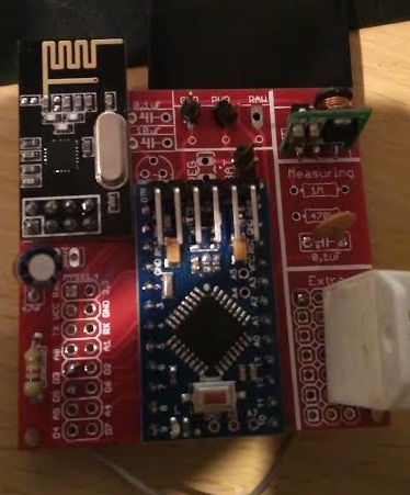
Thanks,
Matt
-
@Matt Hi Matt - tnx.
Try to measure here: whats your reading?
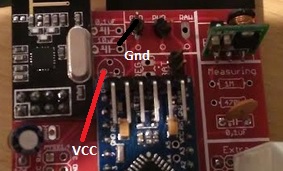
if its 3.3v its your radio thats has some error... this is prettu much the last point before radio. Also measure VCC/GND under the pcb and not on top, what does it say?Sounds like a short or bad solder...
-
@sundberg84
Ah crikey I think Im being thick, I just put a jumper across BAT connectors after tracing the lines and reading the manual, am now getting 2.8 at the NRF. Sorry for being a numpty. Still not picking up on my gateway, time to go to bed but will get the serial monitor running tomorrow....
Thanks for the quick reply.
-
Finally got my boards. In color: Yellow.
If I would skip the Booster is the esiest thing to just wire Vi - Vo?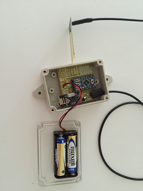
-
I have a question about using this board as a gateway. Pinout of Mini Pro and Nano are almost identical. I built an adapter board to plug in a Nano into this board. Pin by pin control shows it is OK. I checked connectivity with MYSController. The gateway boots up. When I turn on my battery powered sensor, it asks for ID, the gateway "supposedly" sends it. I watch this from the messages. The sensor does not register. It asks four more times, the gateway responds four times. But sensor could not be ID'd and of course registered.
I am thinking either reception problem on sensor side, or transmission problem on gateway side? Could it be a power problem related with design of the board? Is there any way to identify?
Thanks
-
@Valle - yes you can just put a wire between left and right pin - but it wont work for a long time (the pro mini will die when battery goes below 3v i think).
@nunver - I have never used this board as gateway. What does your controller say, does it apply an ID for the request?
-
I'm using mfalkvidds Plant monitoring
mfalkvidd said:An update on battery life: The sensor in my bonsai tree has been reporting every 11,5 minutes since 2015-11-07, so over the last ~four months it has done 24,504 measurements. The battery level has gone from 3.187V to 3.142V, which means a drop of 0.01125V per month. Assuming I let it go down to 2.34V (limit for 8MHz according to the datasheet) and that the voltage drop is linear, I should get (3.187-2.34)/0.01125 = 75 months = ~6 years. There are several error sources in this calculation, but it looks like battery life will be quite good, even though the sensor reports much more often than necessary.
So I will try without Booster. But for other sensors I will use booster.
-
@Valle said:
So I will try without Booster. But for other sensors I will use booster.
Sounds good - let us know how it works out for you. 2,34V is for a genuine Arduino so you know - I dont think a clone manages that... also the last energy (from 1,9 to 2,34v) is not used even though the radio could handle it if you used a booster.
-
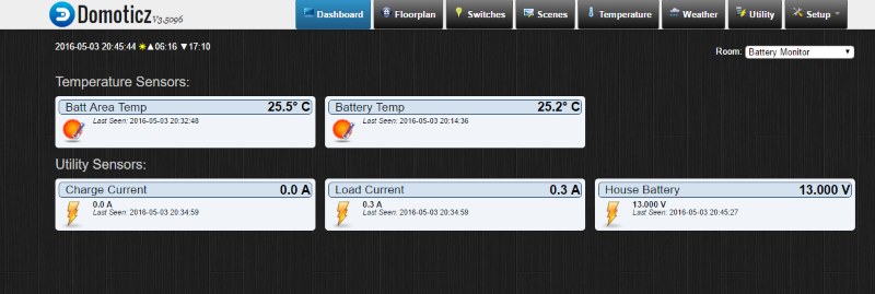
Thanks @sundberg84 for this little board. I have just completed a sensor to monitor the state of our 12v house solar power supply.
It uses an ACS712 Hall Effect Current Sensor Module to keep track of amps in and out of the battery. A voltage sensor to check battery levels and two DS18b20 temp sensors to monitor battery temp and ambient area temp. It reports back to our Domoticz server.
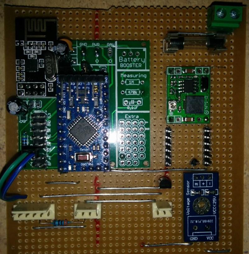
-
@sundberg84 yes it gives an ID of 1, but somehow sensor keeps asking four more times. At the end of the cycle, no ID is set. So no sensor shown.
-
@nunver said:
@sundberg84 yes it gives an ID of 1, but somehow sensor keeps asking four more times. At the end of the cycle, no ID is set. So no sensor shown.
What does the log node say - find parent?
This sounds like either software issue or most probably radio range/power issue,
-
Hello, I'm just finished with 3 cards and test . I read on mysensor.org I'll connect NRF24L01+ Radio whit decoupling capacitor of 47µF and on your card whit 4,7µF
What is the difference?
-
@Affe in practice, there is usually no difference. 4.7uF is enough, but 47uF doesn't hurt.
-
Hello,
I just ordered from DirtyPCB.
Thank you very much for this board which will obviously save me a lot of time with the radio connection.
I'm planning to use the boards for :- as door+temp/humidity sensors for my children's bedrooms, not for the "security"/"safety" aspect but to manage AC more efficiently
- as window sensors for all windows in my appartment coupled with a rain sensor on the balcony, so I can ring an alarm/flash something/sens sms if it starts to rain and one of the windows is left opened. I'm in a tropical country and windows are opened most of the time, with the sudden and strong rains and winds we have sometime it can really be ugly

Power will most probably come from button cells and I will cut the right part of the PCB to fit in small and very cheap plastic boxes I find in shops here. I'm just waiting to see if the test sensor I have put on my entry door survives long enough with a CR2032.
-
Could you give me the size when the pcb is fully soldered as battery sensor?
-
@Nca78 - sounds great, let me know how it works out for you! Good luck!
@Rasenheizung - 50x50cm fully soldered. The dept is about 35mm (Batteryholder + PCB + Components)
-
So - I have a question for the community about boosters. I had a 3.3v Arduino running with my PCB. The radio is connected directly to the battery and the rest through a booster. I experienced alot of st:fails.
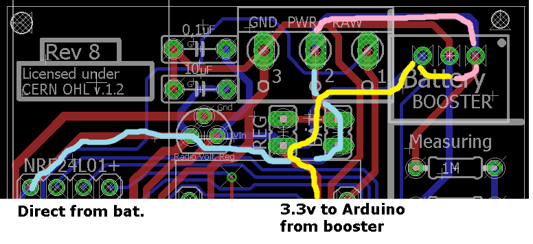
I tested adding a 0.1uF cap on the booster from OUT to GND and the st:fails became st:ok, even though the radio does not get its power from this booster.
Im sure the boosters are in different qualities and renders alot of noice - but could it effect the radio - through the arduino?
If this continues Im going to add the possibility to add this cap on my PCB. (Or maybe its possible to use 0.1uF cap by the voltage divider...)Any feedback ?
-
@sundberg84 typically, I try to add the lc-filter to the booster as some of them are very noisy. This is very simple - 3.3µH Axial lead inducter and a large 220µF capacitor (I use the SMD version). This helps to smooth any ripple effect.
-
Any sort of manipulation, including regulators and boosters, added to any module i would always attempt to filter and smooth the input AND the output of the devices. The noise from the boosters would technically be reaching your radio from those traces. I'm not sure if a diode would stop it from feeding back to the radio, but either way if it did i would still prefer to smooth and filter the power instead of stopping it coming backwards.
-
@sundberg84
it could be multiple things..
But as alexsh1 said you can try to fix it with filtering.You can usea capa + an inductor or a ferrite bead too (a bit different), or a small resistor too can work like a snubber in fact. Generally 0-2ohms<100ohms, but the smaller the better depending of the capa too because it could generate drop out voltage. So for ferrite, it's the same, it's better to use a low ferrite res.
But then, with filtering come some compromise regarding the booster efficiency and the load etc... Use formula and calc or the scope or iterate to choose the better compromise. But that should fix it mostly.There are two main strategy:
- you filter each power input of concerned ics,
- or you filter at powersupply (booster) output because lack of footprint on pcb.
Note :
- it's better for filtering to use small multilayer ceramic capa. low esr, low esl when you can, but again there can be some compromise in this.
- shielded inductor on the booster module is better
- if high esr and esl capacitor used at booster input, then you can have noise back into the batterie, and then propagate elsewhere. If it's your case, and can't fix it at power supply input, try to filter at your radio vcc input with another res for instance and a capa
- there is also the ground loop, having a strong gnd, is better. this is one point why it's useful to use gnd pour plane on your pcb.
- etc...
I hope this will help you a bit

-
Boards received from DirtyPCB, they look gorgeous in white, too bad I have to put those ugly blue nrf and promini boards on top of it

I received exactly 10, they are looking good except the silkscreen 1/2mm too much on the left for some of the boards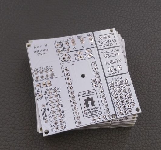
-
@sundberg84 sorry to bother you but maybe you have an idea.
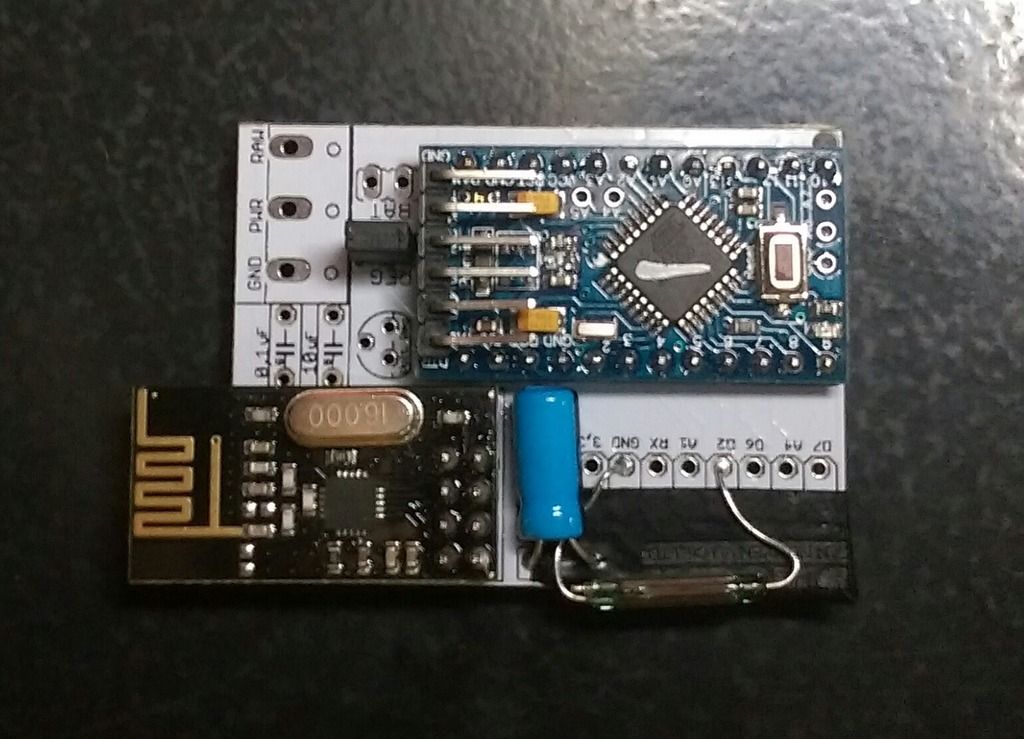
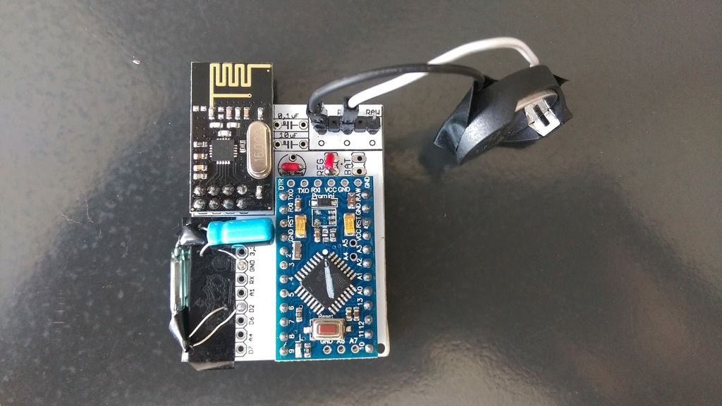
I soldered components as in the picture below (looking so much cleaner than with all the cables...), I am using a 3.3V pro mini.
Before soldering I tested the pro mini and the nrf24 together, connected with cables, and simulated the reed switch with some wires: everything was fine and I was receiving the open/close messages in domoticz.
I soldered the components as below but I only got some "radio init failed" when connected to my PC, power coming to the GND/VCC on top of the arduino.
As I put the jumper on "reg" to bypass the regulator, my understanding is that in this case the raw/power/vcc are all connected together, am I wrong ?Another subject, I suffered to cut the right part of the PCB with a cutter, would it be possible to add some slots along the black line to reduce a bit the length we have to cut ?
-
@Nca78, do you have power on the radio, do you have power present everywhere it should be? Arduino included. If this is all present i would then go into diode mode with a multimeter to make sure all of your pins on the radio are connected to those of the ATMega328 on the arduino.
This would be just a basic starting point at troubleshooting this.
-
@Nca78 - Hi, nice to see your white boards !

I see your image, and you have choosen a REG jumper (regulated power supply). How do you power it? Through RAW?
You have missed the voltage regulator with caps for the radio, so at this point it does not get any power at all?If you are using a 3.3v arudino with RAW you can bypass it with a wire.
If you are using a 5v with RAW or Regulated power (PWR) you need a 5 to 3.3v voltage regulator.
-
@sundberg84
@BastienVH said:@sundberg84 said:
If you use the FTDI connector, make sure its the 3.3v and connect it to Gnd/Pwr on the PCB and not Arduino FDTI connector.
You could just exclude those pins and connect a battery directly and use that as power and the FDTI as programmer/serial debug onlyBat or Reg is nessecary!
See this picture for battery use: https://www.openhardware.io/view/4/EasyNewbie-PCB-for-MySensors
https://www.openhardware.io/uploads/568ed84b60aa3f8965fbf095/image/3.jpg
All components in the image is needed (except battery measurment).
If you dont want to use booster you need to bypass that one with a wire/jumper (or set the jumper on REG instead of BAT but that kills the logic).The battery doesnt "need" the 0,1uF but see here:https://www.mysensors.org/build/battery
"The tap point could be bypassed with a 0.1 uF capacitor to keep the noise level low, at this otherwise high impedance point. "Hi. I've been using this board with 5V power from cell chargers and it works great. I'm trying to make my first battery sensor and am a bit confused (again) as to what is necessary. I'm powering using 2 AA batteries. I've cut the right side off the board so I'm obviously not using the measuring portion, but the above bit about the booster leaves me confused. Can someone answer:
- I connect via the PWR and GND pads right?
- Do I jumper BAT or REG?
- Do I need to do anything else to get this to work?
I tried to program using battery in but was using the ground from the ftdi connector. I could not get this to work. I'm thinking that this was a major problem and that I should have used the battery ground. That's the right approach right?
-
@chuckconnors - assuming you are using a Arduino Pro Mini 3.3v it will die when the voltage drops below 3v (about) so it leaves alot of power left in your batteries and also it will die rather quickly.
Thats why I have designed the PCB with a booster for battery operations, and then its not possible to cut the right side of the PCB since the booster is located there. Check the image out: https://www.openhardware.io//uploads/568ed84b60aa3f8965fbf095/image/Rev8 Bat.jpg and you see the booster on the top right corner.
-
Thank you for the tip @sundberg84, it just needed the bypassing of the regulator, and then I can connect my cell battery to the GND and PWR and it runs fine.
@Samuel235 yes you are right I did it and it didn't have Vcc power that's why I asked that question to sundberg84, next time I'll precise it as it could have ended in wasted time...
@chuckconnors this is how you have to connect the jumpers to use directly on battery power (on GND and PWR pins). But as sundberg84 says you will not have a long battery life with AA batteries and without a booster. Even if you update the fuses and bootloader to run at 1MHz and have the BOD at 1.8V there will still be power left (I guess not far from 25% of capacity with 2 batteries) that is wasted. If you keep the defaults settings of the arduino at 8MHz it will run down to 2.4V and around half of the energy in your batteries will be wasted.
-
@sundberg84 is the board ready for Ver 2.0.0 ?
the final version announced yesterday at HERE, anyhow can you share an example of Node sketch ?
-
@Lior-Rubin - the PCB or the hardware has nothing to do with 2.0
It will work fine - 2.0 is only software (what you program it with).
I have been running 2.0 beta (dev) for a long time now without any problems.
-
@sundberg84 I'm aware of it. I just ask to be sure.
Can you upload here an example sketch (v2.0) with battery reporting ?
-
@Lior-Rubin said:
@sundberg84 I'm aware of it. I just ask to be sure.
Can you upload here an example sketch (v2.0) with battery reporting ?You can just check the examples included in the library, I've been using the beta version of MySensors 2 for a long time and started from supplied examples, never had a problem.
This is some code I use to report battery level, it's harder to make it more simple, juste keep your existing code to read the battery level and replace the line sending the value with the sendBatteryLevel() :
    int currentBatteryPercent = SystemStatus().getVCCPercent(VccMin, VccMax);
    if (currentBatteryPercent != LastBatteryPercent) {
        LastBatteryPercent = currentBatteryPercent;
        sendBatteryLevel(currentBatteryPercent);
    }```
-
@Lior-Rubin - If you use a voltage divider and 2xAA use this:
Defines:
//=========================
// BATTERY VOLTAGE DIVIDER SETUP
// 1M, 470K divider across battery and using internal ADC ref of 1.1V
// Sense point is bypassed with 0.1 uF cap to reduce noise at that point
// ((1e6+470e3)/470e3)*1.1 = Vmax = 3.44 Volts
// 3.44/1023 = Volts per bit = 0.003363075
#define VBAT_PER_BITS 0.003363075
#define VMIN 1.9                                  //  Vmin (radio Min Volt)=1.9V (564v)
#define VMAX 3.0                                  //  Vmax = (2xAA bat)=3.0V (892v)
int batteryPcnt = 0;                              // Calc value for battery %
int batLoop = 0;                                  // Loop to help calc average
int batArray[3];                                  // Array to store value for average calc.
int BATTERY_SENSE_PIN = A0;                       // select the input pin for the battery sense point
//=========================
void batM() //The battery calculations { delay(500); // Battery monitoring reading int sensorValue = analogRead(BATTERY_SENSE_PIN); delay(500); // Calculate the battery in % float Vbat = sensorValue * VBAT_PER_BITS; int batteryPcnt = static_cast<int>(((Vbat-VMIN)/(VMAX-VMIN))*100.); Serial.print("Battery percent: "); Serial.print(batteryPcnt); Serial.println(" %"); // Add it to array so we get an average of 3 (3x20min) batArray[batLoop] = batteryPcnt; if (batLoop > 2) { batteryPcnt = (batArray[0] + batArray[1] + batArray[2] + batArray[3]); batteryPcnt = batteryPcnt / 3; if (batteryPcnt > 100) { batteryPcnt=100; } Serial.print("Battery Average (Send): "); Serial.print(batteryPcnt); Serial.println(" %"); sendBatteryLevel(batteryPcnt); batLoop = 0; } else { batLoop++; } }Add batM(); in the loop where you want to measure.
This calculates an avarage and sends it every 3rd time. So i sleep my sensors for 20 min, and battery is reported every 1hour.If you want to measure incoming VCC agains ref use @Nca78 but this does not work if you are using a booster (since it will always be 3.3v on incoming).
-
Hello @sundberg84 I have a request for update for your board

Can you remove the trace from the INT pin of the NRF24 to the D2 pin of the pro mini ? As interrupt is not used in MySensors for the NRF24, it's not useful while it creates some side effects.I explain you my problem:
I made a door sensor using a reed switch with both normally open and normally closed pins, and connected them to D2 and D3 (+ ground on the other side connected, as on my last picture above).
In the code I switch the status of the pins in the loop between HIGH/LOW values and set the interrupt on the unconnected pin so the pin is connected to ground only during a very short time (just the time to get out of the sleep mode). I'm supposed to have a very low consumption during deep sleep mode (few microamps). But I have that only when D2 is not connected to ground. If it's connected then it seems I have some current leaking from the INT pin of the NRF24 to the ground through the reed switch, as the board is using 6.5mA.
Without any other change, I made a barbaric cut of the trace near the NRF24 and now the current consumption is around 1.5 µA for both states of the reed switch. For the next boards I will just remove the INT pin of the NRF24, but it would be more simple to have nothing to do
Just in case this is my sketch (not final, please be tolerant) but I don't think it's really relevant
// Enable debug prints
#define MY_DEBUG

// Enable and select radio type attached
#define MY_RADIO_NRF24

#include <SPI.h>
#include <MyConfig.h>
#include <MySensors.h>
#include <SystemStatus.h>

#define SKETCH_NAME "NCA Door Sensor"
#define SKETCH_MAJOR_VER "0"
#define SKETCH_MINOR_VER "7"

#define PRIMARY_CHILD_ID 30
#define SECONDARY_CHILD_ID 4

#define PRIMARY_BUTTON_PIN 2   // Arduino Digital I/O pin for button/reed switch
#define SECONDARY_BUTTON_PIN 3 // Arduino Digital I/O pin for button/reed switch

#if (PRIMARY_BUTTON_PIN < 2 || PRIMARY_BUTTON_PIN > 3)
#error PRIMARY_BUTTON_PIN must be either 2 or 3 for interrupts to work
#endif
#if (SECONDARY_BUTTON_PIN < 2 || SECONDARY_BUTTON_PIN > 3)
#error SECONDARY_BUTTON_PIN must be either 2 or 3 for interrupts to work
#endif
#if (PRIMARY_BUTTON_PIN == SECONDARY_BUTTON_PIN)
#error PRIMARY_BUTTON_PIN and BUTTON_PIN2 cannot be the same
#endif
#if (PRIMARY_CHILD_ID == SECONDARY_CHILD_ID)
#error PRIMARY_CHILD_ID and SECONDARY_CHILD_ID cannot be the same
#endif

#define MY_NODE_ID 2
#define MY_PARENT_NODE_ID 0


// Change to V_LIGHT if you use S_LIGHT in presentation below
MyMessage msg(PRIMARY_CHILD_ID, V_TRIPPED);
//MyMessage msg2(SECONDARY_CHILD_ID, V_TRIPPED);


// Parameters for VCC measurement
const int VccMin        = 2400;  // Minimum expected Vcc level, in Volts. If you have updated bootloader&BOD you can change to 1.8V here
const int VccMax        = 3000;  // Maximum expected Vcc level, in Volts.
SystemStatus vcc();
int LastBatteryPercent = 200; // so we are sure to send the battery level at first check
bool isEven = false; // to check+send battery level only for each open+close cycles


// This is the activated pin, on which the interrupt is set
byte connectedPin = PRIMARY_BUTTON_PIN;
byte connectedPinAtLastSending = 0; // Initialized at 0 so we will always send the first time

void setup()
{
  // First thing to do: change clock prescaling to 8 to change from 8MHz to 1MHz
  //  of course not necessary if you already have updated fuses and bootloader...
  #ifndef MY_DEBUG           // only if we are not in debug mode, so we can keep the fast baudrate in debug
    clock_prescale_set (clock_div_8);
  #endif

}

void presentation() {
  // Send the sketch version information to the gateway and Controller
  sendSketchInfo(SKETCH_NAME, SKETCH_MAJOR_VER "." SKETCH_MINOR_VER);

  // Register binary input sensor to sensor_node (they will be created as child devices)
  present(PRIMARY_CHILD_ID, S_DOOR);
}

// Loop will iterate on changes on the BUTTON_PINs
void loop()
{
  // Short delay to allow buttons to properly settle
  sleep(5);

  deActivatePin(PRIMARY_BUTTON_PIN);
  deActivatePin(SECONDARY_BUTTON_PIN);

  // Check if the previously connected pin is now connected. We do that because it's the most likely to be unconnected now
  //  so it's the best way not to lose any current
  byte newConnectedPin = GetNonConnectedPin();
  if (checkPinIsConnected(connectedPin)) {
    // If pin is still connected we set back the value to connected pin
    newConnectedPin = connectedPin;
    #ifdef MY_DEBUG
      Serial.println("Connected pin is connected !");
    #endif

  }
  connectedPin = newConnectedPin;
  // If connected pin is different that the one during the last sending of status, we send again
  #ifdef MY_DEBUG
    Serial.print("Connected pin = ");
    Serial.println(connectedPin);
    Serial.print("New Connected pin = ");
    Serial.println(newConnectedPin);
  #endif

  if (connectedPin != connectedPinAtLastSending) {
     // Value has changed from last transmission, send the updated value
     send(msg.set(connectedPin==PRIMARY_BUTTON_PIN ? 1 : 0));
     connectedPinAtLastSending = connectedPin;
     isEven = !isEven;
  }

  if (isEven) {  // send only every two changes for a full open + close cycle
    int currentBatteryPercent = SystemStatus().getVCCPercent(VccMin, VccMax);
    if (currentBatteryPercent != LastBatteryPercent) {
        LastBatteryPercent = currentBatteryPercent;
        sendBatteryLevel(currentBatteryPercent);
    }
  }

  #ifdef MY_DEBUG
    Serial.print("Preparing to sleep, pin ");
    Serial.println(GetNonConnectedPin());
    wait(50);
  #endif

  // Activate the non connected pin before setting up interrupt
  activatePin(GetNonConnectedPin());
  // Sleep until something happens with the door sensor
  sleep(GetNonConnectedPin()-2, CHANGE);
}

void activatePin(byte pin) {
  // Set pin as input
  pinMode(pin, INPUT);
  // Activate internal pull up
  digitalWrite(pin, HIGH);
}

void deActivatePin(byte pin) {
  // Set back pin as output, low
  pinMode(pin, OUTPUT);
  digitalWrite(pin, LOW);
}

// Will check if pin is grounded (returns true) or not
boolean checkPinIsConnected(byte pin) {
  activatePin(pin);

  // Read value
  byte valPin = digitalRead(pin);
  deActivatePin(pin);

  #ifdef MY_DEBUG
    Serial.print("checkPinIsConnected pin = ");
    Serial.print(pin);
    Serial.print(", value = ");
    Serial.println(valPin);
  #endif

  return valPin != HIGH;
}

// Returns the pin that is not connected
byte GetNonConnectedPin() {
  return (connectedPin == PRIMARY_BUTTON_PIN) ? SECONDARY_BUTTON_PIN : PRIMARY_BUTTON_PIN;
}
-
@Nca78 Thanks. Someone else posted this as well. I will update this Inow rev 9 with some jumper or something.
-
Another real quick question. I have a simple sensor using a DHT11. I have this connected to D3 for signal and power and ground from the right holes. I'm getting an error saying it can't read temp/hum from the DHT. That set up should be right though? I also have a 4.7k ohm resistor in the board for D3 (that's the pin, right?).
-
@chuckconnors - that right, see my post at 110 (https://forum.mysensors.org/topic/2740/easy-newbie-pcb-for-mysensors/110)
I have the dht22 in the prototyping area but have made alot of dht22 attached directly to power/gnd and d3 pin on the mysx connector. Works great.
-
@sundberg84 Thanks. Another dumb question: What is the difference between the RAW ad the PWR pads and when should I use one rather than the other?
-
If you have unregulated power (RAW) within pro minis on board voltage regulater you can instead of using 5v regulated power use this and the arduino will convert it to 5v. I think the specs are 6-12v (with a varning on that clones can not handle 12v!). So for example if you have a 9v battery you can power everything with connecting this to RAW and GND instead of PWR and GND and the voltage regulater on the pro mini will output 5v for the rest of the PCB. @chuckconnors
-
what is the size of the mounting holes? i don't have a caliper yet to measure this small of a size (ordering on amazon)
-
Just wanted to say great work on this board. I have the first one wired up w/ batteries, 3.3v APM w/led and regulations removed, voltage regulator, dht11 and motion w 3v mod and works wonderfully. Once I get my caliper in, I'll get the right mounting screws, finish my enclosure and post the pics.
-
@rchamp said:
what is the size of the mounting holes? i don't have a caliper yet to measure this small of a size (ordering on amazon)
I dont have eagles at this computer, so I have to answer you tonight (8 hours) or so...
Thanks for the nice feedback!
-
@rchamp - sorry for later reply, the mounting holes are 2mm or 78.7mil.
-
@sundberg84
awesome thanks!
-
Hello, I ordered a second batch from PCBWay, it's ok except some components have a frame on the silkscreen, not very beautiful.
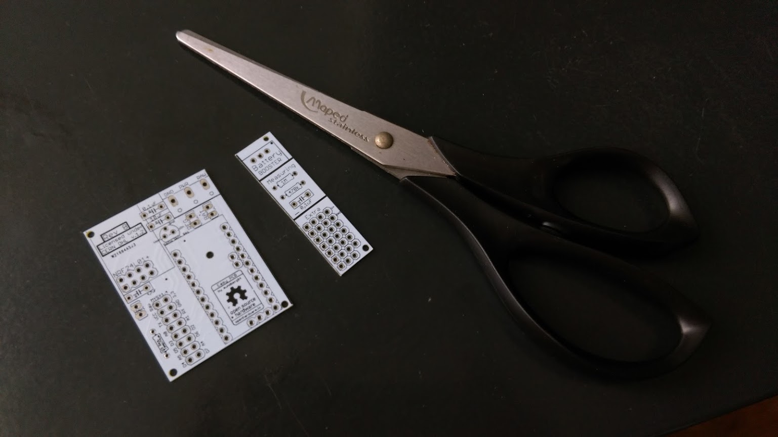
Just wanted to say that it was a pain to cut the 1.6mm PCB so this time I ordered in 0.8mm and it is sooooo easy to cut with regular cissors: no efforts and very clean cut ! So if you plan to cut the right part, order at 1mm or below, you will enjoy the cutting phase
-
@Nca78 said:
it's ok except some components have a frame on the silkscreen, not very beautiful.
Sorry, I dont understand what you mean - can you give me a closeup photo? It should be functional AND beautiful
 If the silkscreen overlaps the copper parts this could interfer as well...
you will enjoy the cutting phase
I also learned it the hard way - and since there isnt any high power ciciut it should be ok to order very thin pcbs.
I used a metallic saw for one and for some i cut a trace with a knife and bended it until it cracked.
-
Just ordered 10 white bords, they look so great

-
@sundberg84 said:
Sorry, I dont understand what you mean - can you give me a closeup photo? It should be functional AND beautiful
 If the silkscreen overlaps the copper parts this could interfer as well...
I fact it's the case only for the "Rev B" and licence text at the top left. No big deal but it was looking better without the frame from DirtyPCB
I also learned it the hard way - and since there isnt any high power ciciut it should be ok to order very thin pcbs.
I used a metallic saw for one and for some i cut a trace with a knife and bended it until it cracked.
I used the knife too (don't have a metal saw) with the 1.6mm PCBs and it was long and messy. Now it's just like a strong cardboard.
-
I ordered some via DirtyPCB - Ordering via OpenHardware it seems to suggest you are buying Rev4. Says Rev4 under the order button at least.
-
@Qu3Uk - Yes, and its missleading. Its rev 9 you are ordering but the fourth update on openhardware.io Its no problem ordering from there, I always update those gerber files first.
-
I just wanted to make some suggestions for this board for the possible next revision. I recently ordered a 10 pack (which when I got it ended up being an 11 pack... BONUS BOARD).
When I put together my first board there were some things that I noticed. First, the boards that I got are labeled as rev 8 boards, but there is one small difference from the one shown on the openhardware.io website.

The placement of the 4.7uf capacitor and the raw power connection holes next to the nRF24L01+ socket are reversed. The spot that you have for the 4.7uf capacitor for the nRF24L01+ radio module is just a bit too close to the nRF24 connector. It appears that the capacitor that you chose in your design software was for a ceramic type cap that has a wider hole spacing and is narrower. Choose one for an electrolytic cap and move it away from the nRF24 connector a bit more. This should give the closer hole spacing designed for a small electrolytic cap and leave enough room for it.Similarly the spot you have for the 10uf cap above the regulator appears to also be a design for a ceramic cap with the wider hole spacing. Selecting electrolytics for these should not only give you the correct hole spacing for the electrolytic, but it should also better mark where the negative lead of the cap needs to go on your silkscreen layer.
The other thing that I wish this had was pads for a SMT AMS1117 regulator. This could be placed in the space under the nRF24 radio or just under the pro mini. You could do this in conjunction with the TO92 style that you have currently placed. It would give the board a bit more flexibility for users. In my parts box, I only had the AMS1117 regulators and not the TO92 style. I have since ordered some of the TO92 style, but having the flexibility for either would have been nice.
Last but not least, it would be nice to have slightly larger corner mounting holes. I don't have many small screws that fit those holes, and I have none that would work with the standoffs that I use.
Other than those few things, it seems like a rock solid board. Thanks for the hard work.
-
@dbemowsk - Hi!
Thank you for great input!Why the difference, is because I released rev 8 but made some last minute changes and forgot to update to rev 8.1.
You pretty much found the difference. It was a couple of days so I didnt think anybody would notice.
Did you order from DirtyPCB? I see not it got the old rev 8 version. I will update openhardware.io!Your suggestions about the 4,7uF cap is exactly what I did in the correct Rev 8 version.
I use electrolytic caps on both 4,7 0,1 and 10 uF without any problems. The G marks ground.I also like the AMS1117 but since its another design than LE33 and MySensors site wuggest LE33 i went with this.
Its a balance between flexibility and easy to use. To many components (like dual voltage regulators) will confuse some new users.I will try to fit in some bigger holes in rev 9 (currently working on it) and see what I can do about the AMS1117 .
Thank you for great input - ill keep it in mind!Br
Andreas
-
Hi,
First of all, thank you @sundberg84 for this great PCB. Super easy to work with. Still; there is one question that I haven't been able to figure out yet.
I'm running my pcb as a battery node and want to monitor the battery status. However A0 always returns a value somewhere around 30 +/- 15 - even with brand new batteries. Calculated into voltage, this would mean around 1,04V.
I've checked and double checked that I'm using 470k and 1M resistors.
I've also measured using a multi meter, with incoming value of 3,2 V and outgoing from booster 3,36V.Any ideas that might point me in the right direction for solving this noob issue?
-
@daand83 - do you mean analogread() always returns 30 but you still got 1,04V in? If so, either you have a bad connection to A0 or the chip is broken. I have had atmegas (pro mini) which was broken.
You could try soldering a second wire from A0 to the voltage divider to exclude connections errors. You could also measure the voltage input on the atmega chip. If its 1.04 there as well a bad connection can be excluded and you hav a bad pro mini / atmenga chip.
It coule be a code error as well, if you have changed to code...
-
@sundberg84
Hi,What I've done is this;
Measured voltage on PWR/GND which returns 3,2 V. I've measured voltage on GND/Vout on the battery booster which returns 3,36V. However, analogread always returns something like 300 +/-10, which (using the formula provided) indicates a voltage of 1,04 V and a battery percentage of ~30%. This has been the case with brand new batteries as well as old ones...
-
@daand83 - this is quite dependent on which code you use I think but it sounds right. A return of 1000 would be 3,3V in my code.
This is my code:
Defines:
//=========================
// BATTERY VOLTAGE DIVIDER SETUP
// 1M, 470K divider across battery and using internal ADC ref of 1.1V
// Sense point is bypassed with 0.1 uF cap to reduce noise at that point
// ((1e6+470e3)/470e3)*1.1 = Vmax = 3.44 Volts
// 3.44/1023 = Volts per bit = 0.003363075
#define VBAT_PER_BITS 0.003363075
#define VMIN 1.9                         //  Vmin (radio Min Volt)=1.9V (564)
#define VMAX 3.0                        //  Vmax = (2xAA bat)=3.0V (892)
int batteryPcnt = 0;                       // Calc value for battery %
int BATTERY_SENSE_PIN = A0; // select the input pin for the battery sense point
//=========================
Setup()
analogReference(INTERNAL); // For battery sensingLoop()
delay(500);
   // Battery monitoring reading
   int sensorValue = analogRead(BATTERY_SENSE_PIN);
   delay(500);

   // Calculate the battery in %
   float Vbat  = sensorValue * VBAT_PER_BITS;
   int batteryPcnt = static_cast<int>(((Vbat-VMIN)/(VMAX-VMIN))*100.);
Serial.print("Battery percent: ");
Serial.print(batteryPcnt);
Serial.println(" %");

if (batteryPcnt > 100) {
     batteryPcnt=100;
 }

Serial.print(batteryPcnt);
Serial.println(" %");
gw.sendBatteryLevel(batteryPcnt);
I think you should measure the voltage on A0 to Gnd and see what you get.
-
@sundberg84 - the only weird part is that analogread() returns a value of 300, which in turn is below VMIN; and hence a negative value (1,04-1,9)/(3,0-1,9) = -78%.
But if I understand you correctly the next two steps in the troubleshooting process would be;
- measure GND/VCC on the atmega-chip as well to make sure that it is indeed not a faulty chip?
- solder a second connection from A0 to the voltage divider to remove any bad connections
Thanks again


-
I have to verify when I get home, but I've probably found the problem... Seems as a stupid copy/paste problem. No call to analogreference(INTERNAL). Don't know how I've been able to overlook this for a week now, but... Will check back with result later on...
-
@daand83 - haha, easy to forget - I also forgot to post in in my example above (changed now)

Only one line of code in a different place... well, hope you found it!
-
@sundberg84 - Indeed missing analogreference. All good now, even got a battery value of 102 %

-
@sundberg84 said:
AMS1117
mmmm I would like to see a board with room for AMS1117 and caps...

While waiting for my Newbie PCBs to arrive I have built my own test sensor on a bit of breadboard. Got the new 0,8-3.3v to 3.3v today. My boosters. So, I just cut the trace going from the battery to the rest of the components and arduino and there I connected my booster. VIN directly from bat + and gnd from bat -, Also, everything else that need GND is connected to the same place. I then reconnected the plus power rail to the power coming from the booster. I also moved the radio connection so that if feed directly from the battery. Measurements show me 3.3 v to arduino and other sensors and about 2.9 to the radio directly from batt. Something does not want to work. It is something with the power to the radio. Running sensor on battery only, no booster, works just fine. Running node with everything on vout from the booster, it just won't work. The radio struggles to do something useful but it fails. Running radio on batt and the rest on booster does not work. 'But, if I power the node with power from the serial adapter. the node woks again but only if the battery provide power to the radio at the same time.
Any suggestions? Quite tired, can be messy

-
@NiklasO - do you have any serial log?
2,9V should be just fine for the radio, but it might freeze with spikes from booster or other power circuit. A 0,1cap from Out to Gnd on the booster might help.Try to remove the booster and verify if the radio works then - if so, its the booster. If not try another radio - we know the radios is very different quality sometimes.
-
Hello, I think @sundberg84 is right, you need some capacitors to filter the noise from the booster, the best is to put the same than those that are on EasyPCB (top of the voltage regulator).
Even if you power the radio directly from the battery, the booster will generate some noise if you use it to power the board, as they have the same GND.
-
@sundberg84 said:
@NiklasO - do you have any serial log?
2,9V should be just fine for the radio, but it might freeze with spikes from booster or other power circuit. A 0,1cap from Out to Gnd on the booster might help.Try to remove the booster and verify if the radio works then - if so, its the booster. If not try another radio - we know the radios is very different quality sometimes.
Thanks for the answers guys!
Everything works as it should when all on battery.
Out to GND already have a cap. The same one the radio use? If it sits between radio vcc and gnd-pin that would be the same as between Vout and GND on the booster, right? I have tried with caps at 0,1 - 100uF. The current one is at 47uF. The serial log say stuff about signing error and other like !TSM:UPL:FAIL when radio on battery and the rest on booster Vout. Reports radio OK at start. All has the same GND.
The multi meter show a quite stable 3.3v output from the booster but I don't have any oscilloscope to see the eventual noise. I have tried different boosters but all are probably the same batch, marked "Canton-power" I think. Also, the radio seem to freeze the Gateway. My sensor tries to communicate with the gateway (I have green, yellow, and red leds connected to both gw and my testsensor). On the sensor the yellow and green blink momentarily and then it greets me with angry red led blinking at me. The gateway does the same ofc but often it freezes with all the three leds constantly on. To make the gateway accept connections again I have to reset it but this does only happen with this troublesome sensor with radio on bat, rest on booster. Other than that the gateway works great with my other sensors (all on battery only for now).
-
You have to combine different capacitor values to have some efficient filtering.
If you respect what is implemented on EasyPCB board you should have :- 0.1µF and 10µF as close as possible to the booster output
- your 47µF as close as possible to the GND/VCC of the radio
Location of capacitors is important as if they are far from the radio for example, the wires to the radio act as antenna and will catch noise generated by the booster. So in addition to the capacitors at the right position, try to have wires going to the radio as short as possible.
-
@Nca78
Ok, thanks.
I'll try some more.
-
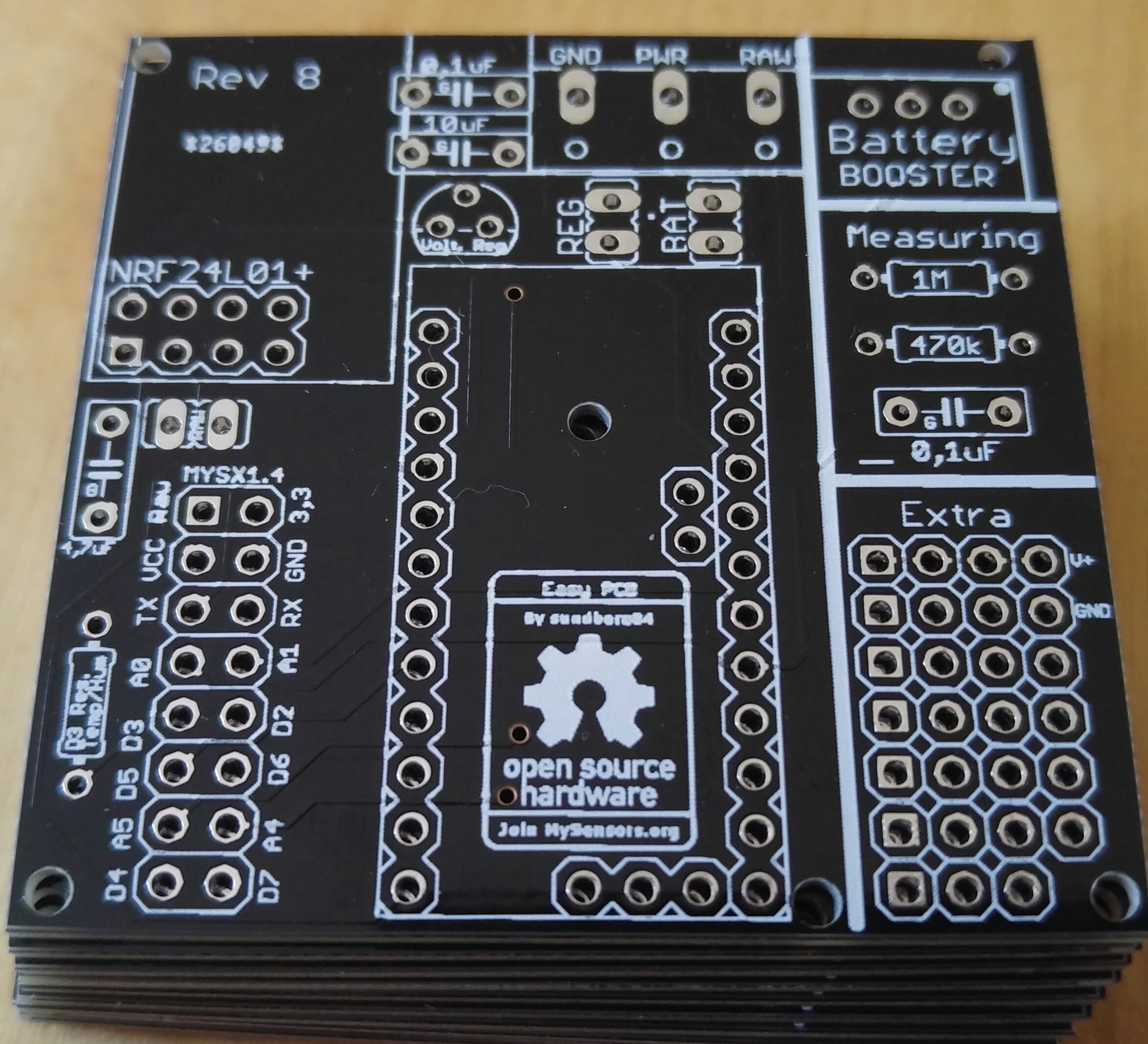
My Dirty boards arrived today! Woho! Got 12 of them.
-
Just wanted to say that my first sensor on this board works great! Measuring passives in place. Worked first try.
On battery, with booster and one DS18B20 temperature sensor.Great work @sundberg84!
-
@sundberg84: I have plan to use your pcb to build ethernet gateway, thus I want to use NRF24L01+ radio with external antenna. In this case it's more than recommended to use external power to supply the radio as pro mini has not enough juice to feed radio properly. Could you please give me some hint how to do it in most elegant way? I think it should be enough to do not solder radio's vcc and gnd pins to pcb, but to connect external power supply to these pins with hardsoldered capacitor. What do you think?
-
@fisher - that is exactly what I did... i made a external "powerpcb" which i could connect the radio to and the node (Arduino + Ethern module) to. This way I didnt feed the radio from the arduino. Be sure to use a voltage regulator with a good ampere output.
Check this: https://www.openhardware.io/view/207/Mysensors-20-ethernet-gateway-W5100-build
-
@sundberg84: thx for the quick response. I saw your post with external ethernet gateway but I'd like to avoid use of jumper wires and use your newbie psb instead
-
@fisher - well, the only option then is to use a 3.3v arduino on my PCB and BAT jumper. Then make sure you have a steady 3.3v on PWR on the PCB. If you have any units (like ethernet module?) that needs 5v you need a step up for this... i guess there are many ways to solve this but I have not tried them so you need to experiment a little.
-
@sundberg84: I think I have to abandon my idea to use Newbie PCB as there is slightly different wiring required for connecting w5100 module. I will solder it on prototype board instead. Thanks for your help
-
@sundberg84
I really like this design. Do you have plans to make a version for the RFM69W radio? Shouldn't be to difficult but with the free version of eagle, I can't edit your design.
-
@FotoFieber - that shouldnt be any problem editing. Do you try to open the gerber files, you need to open .sch and .brd
-
So I have one more flaw to point out in the board that I didn't notice before. I also have a question regarding powering the nano. I'll start with the problem and this is for @sundberg84 . Some weeks back I posted some suggestions and differences that I noticed in the revisions of the boards. This was the pic:

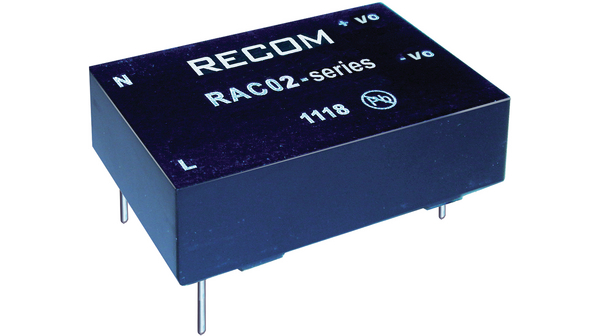
When I posted that, you noted that for the capacitors, the G denotes ground. If you look at the blue board on the right which is the one that I have, you have the G marked on the left leg of the capacitor. If you measure continuity from that pin to the large ground tab for incoming power, you will notice that that is not ground. The one on the right is. Since I got the boards, I have always teeted for continuity for my ground legs, so I haven't had any issues, but for a newbie, which is what the board is geared toward, there could be issues.Now on to my question regarding power. So I am building another node and I am using the 5 volt version of a Recom power module
 .
.
Seeing that this is a 5 volt output, I would think I should be able to go directly to the 5 volt in on the nano, but what is the best way to wire this if I am using a screw terminal connector to bring my power in? The RAW power pad goes to the regulator input on the nano, and the PWR pad goes to the battery booster which I am not using. I would also guess that I would need to jumper the BAT pads. Would I then too want to remove the regulator from the nano, or won't that matter?Any help is appreciated.
-
@dbemowsk - thanks for your unput! I have checked my project and changed the G label.
I will also make an notise on openhardware!You should be able to use that just fine as power. Most people here use HLK-PM01 but this might be a great addition! (Havent seen it before).
Check this thread out: https://forum.mysensors.org/topic/1607/safe-in-wall-ac-to-dc-transformers. You should connect it to PWR and GND with REG jumper short.
-
@sundberg84 said:
this might be a great addition! (Havent seen it before).Unfortunately it's not the same price range as HLK with 12$95 from all suppliers linked from their website.
Could still have been nice if it had "physical" advantages compared to HLK but it's bigger and with lower power.
So it's got the safety of a German product left, but HLK is safe enough provided we get a genuine one.Interesting part is the recommended circuit which is similar to the one suggested here for the HLK with input fuse, varistor for use with 230V source and optionnal output capacitor to reduce ripple. No temperature fuse but I suppose with bigger size, lower power and higher quality components it's getting really overkill.
-
I ended up ordering 3 of these. I got them from this site. It wasn't till after I ordered them that I saw a post on here about the HLK-PM01 modules. I see the better advantages of the HLK series, cost being the big one, and will order these in the future as needed, but I am just trying to use up the 3 of these that I have.
I have another project I am working on where I might order some HLK-PM12 modules. I ended up getting a lot of 10 - 12 or 24 volt relay modules for free that I figure I can use in some projects. I wish they were 5 volt, but it's hard to argue with FREE.
-
Hello,
I'm using the temperature sensor (DS18B20) on a card v8.
Ok if I use a 18650 battery, if I use a CR2032 coin battery, the sensor does not work.
I have to make some adjustments?
-
@fabix68 Your problem might be in the fact that the 18650 battery is a 3.7 volt battery, where the CR2032 is only a 3 volt. The extra 0.7 volts will make all the difference. If you use a CR2032, there are a few things you want to do. The first thing is that you need a battery booster. This will boost your power from 3 volts to the needed 3.3 for the nano and the radio. Next is to remove the LED from your nano. This will put unnecessary load on your battery and drain it much faster. You may even want to remove the regulator from the nano.
-
I'm already using a booster to the battery and removed led and regulator. I partially solved by inserting in parallel to battery a 10mF capacitor
-
What are your setup @fabix68 ? If you are using a 3.3v arudino straight on it will not work.
Please describe your setup and hardware and not only your battery,