What did you build today (Pictures) ?

-
-
My 3V Node (Atmega328P 1MHz), embedded NRF24L01+ with ceramic antenna, ATSHA256, AT25DF512, BME208, LED, Battery monitoring, ICSP, FTDI, Castelizable, Breadboardable.
-
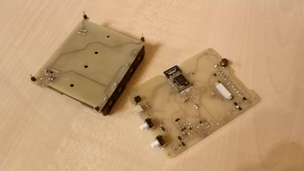
Today finished with the HW part of the new device
-
Great idea @sundberg84
This prompted me to finally get started on something that I've put off for far too long, especially considering how little work it was.I'm still using dupont wires to connect my radios, despite better solutions such as the easypcb being available. But this quick little trick makes it easier to switch the radio modules.
https://youtu.be/Jeg0kS9AcgYYou'll need:
- Dupont female-female wires (I use 10cm), https://www.aliexpress.com/item/Free-Shipping-1lot-40pcs-lot-10cm-2-54mm-1pin-femal-to-femal-jumper-wire-Dupont-cable/32329983091.html
- 4x2 jumper wire connector/header from a 620 pcs kit, https://www.aliexpress.com/item/620-Pcs-1-Set-Jumper-Wire-Cable-Pin-Header-Connector-Kit-Male-Crimp-Female-Pin-Terminal/32816829548.html
- NRF24L01+ radio module, https://www.aliexpress.com/item/Free-shiping-best-prices-10pcs-lot-NRF24L01-NRF24L01-Wireless-Module-2-4G-Wireless-Communication-Module/674686536.html
- Small screwdriver
In the future, I plan to build the other end of the connector for Pro Mini and Rasbperry Pi.
@mfalkvidd
Looks impressive! -
-
Today.... This MQ2 gas sensor with Neopixel RGB lamp on top and a capacitive touch button under the circle mark on the front.
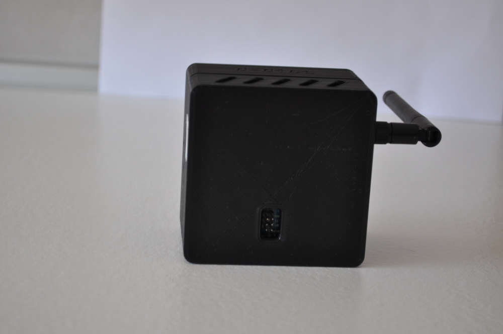
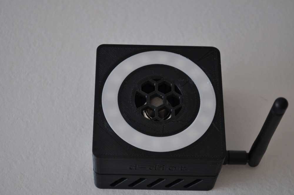
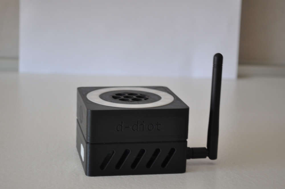
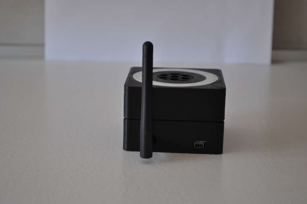
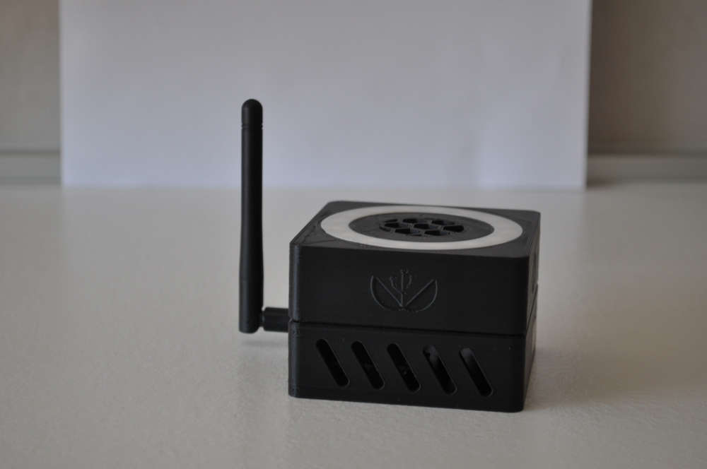
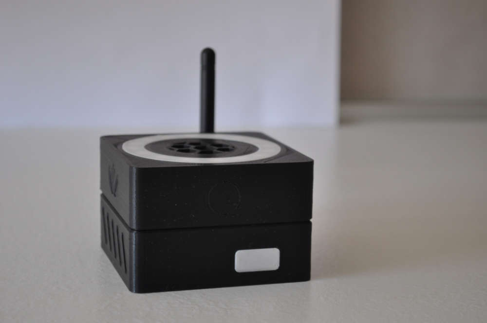
It is part of the d-diot project. The files of the 3d-printable case are available in Thingiverse.
The firmware is available here, the wiki page is under construction.
In the next weeks I will try to print it in wood... Just to increase the WAF :wink:
-
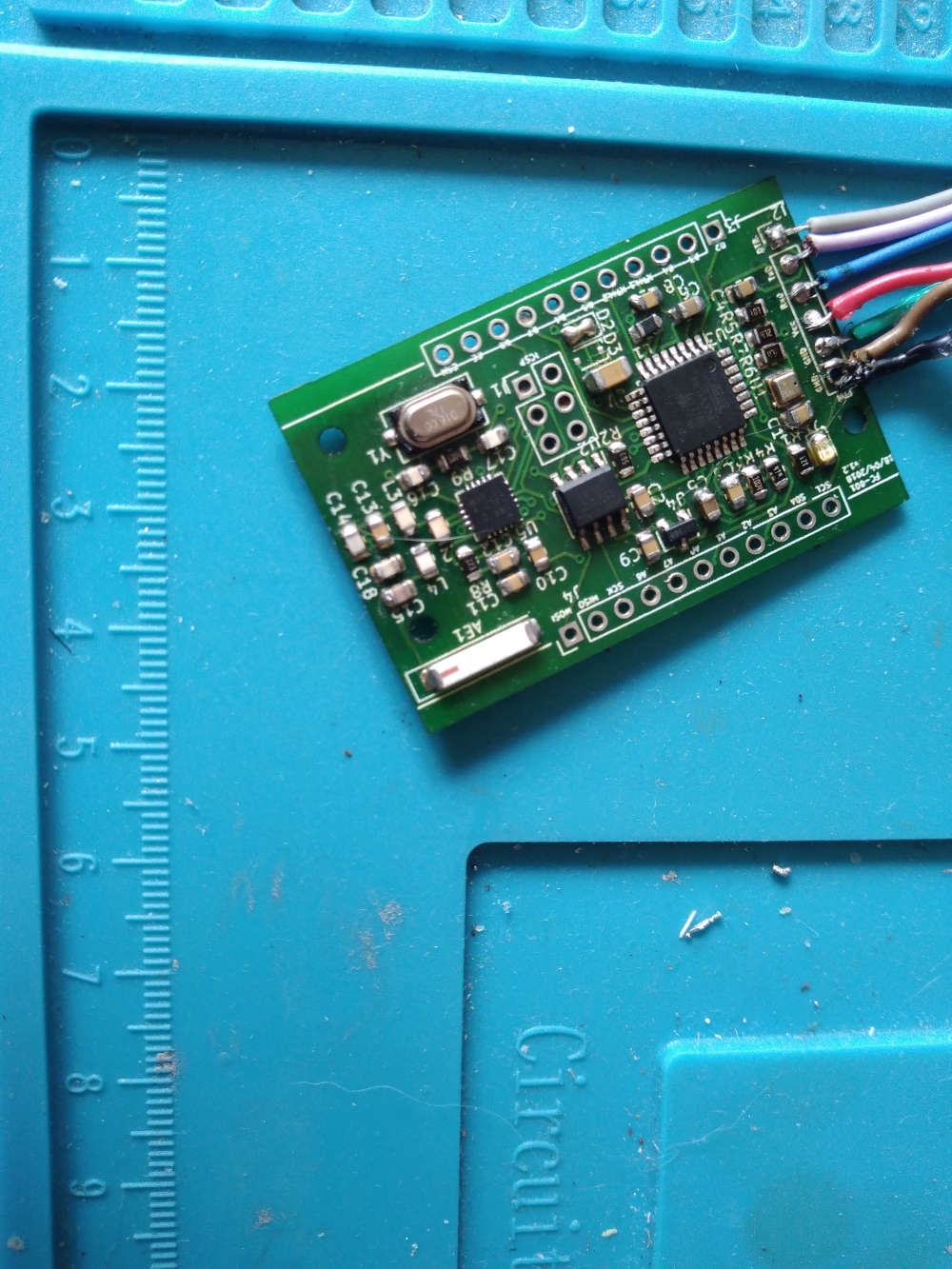
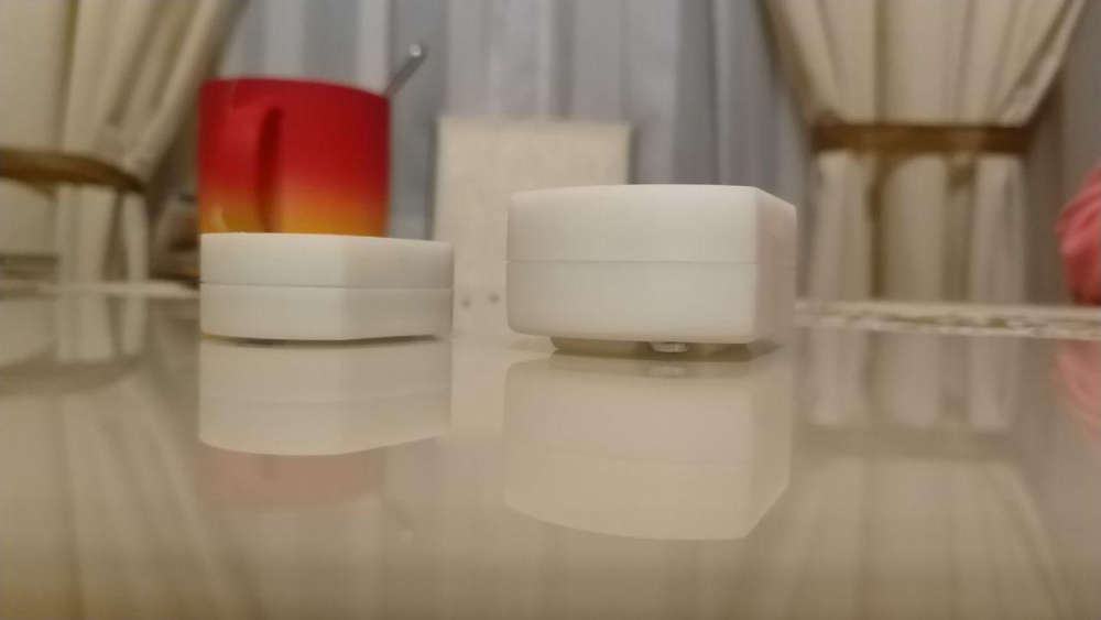
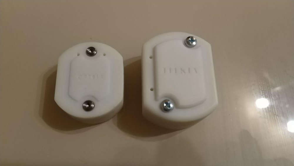
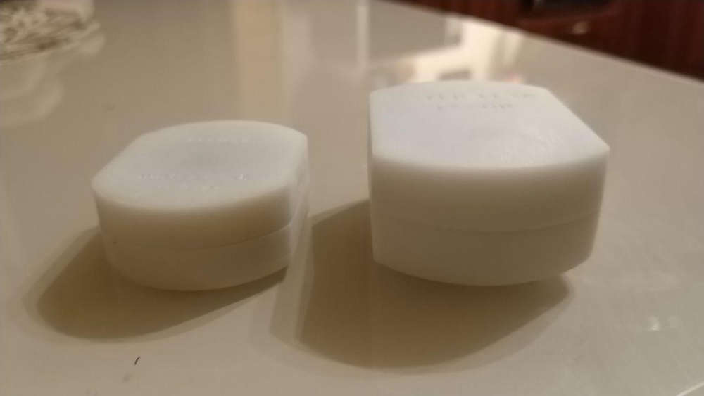
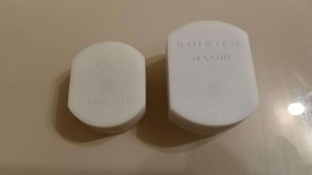
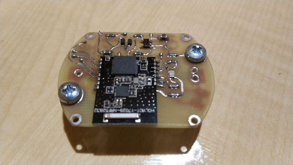
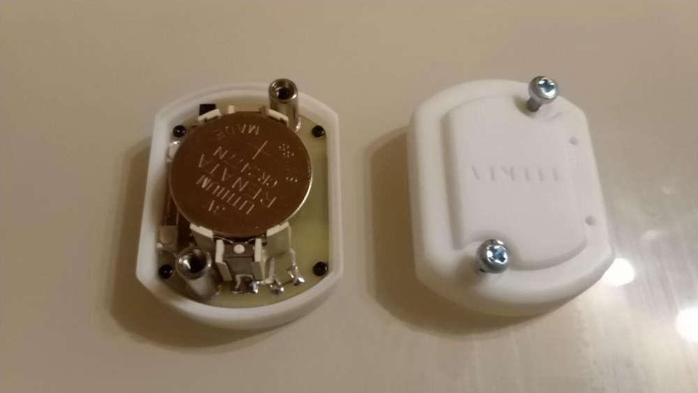
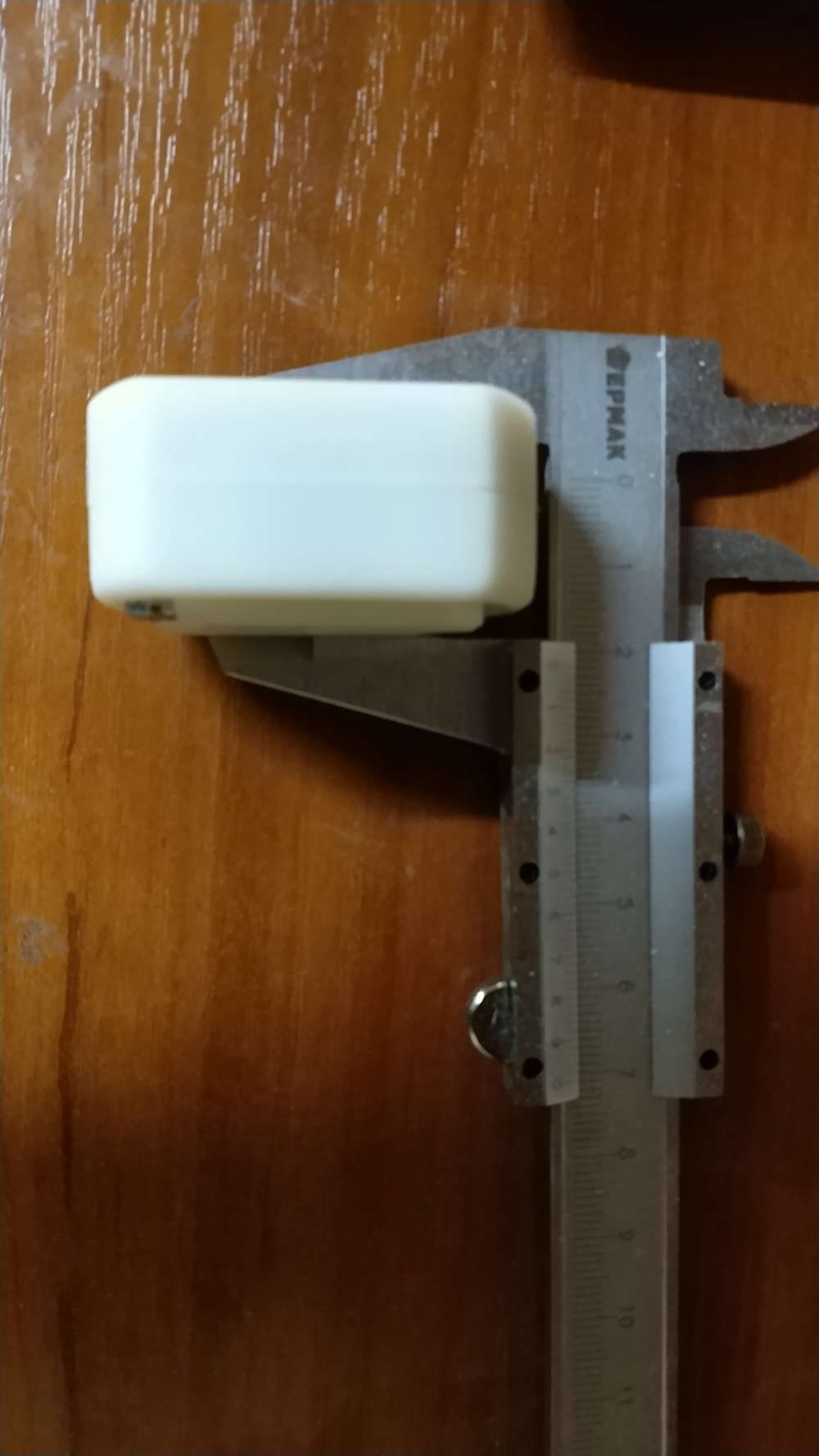
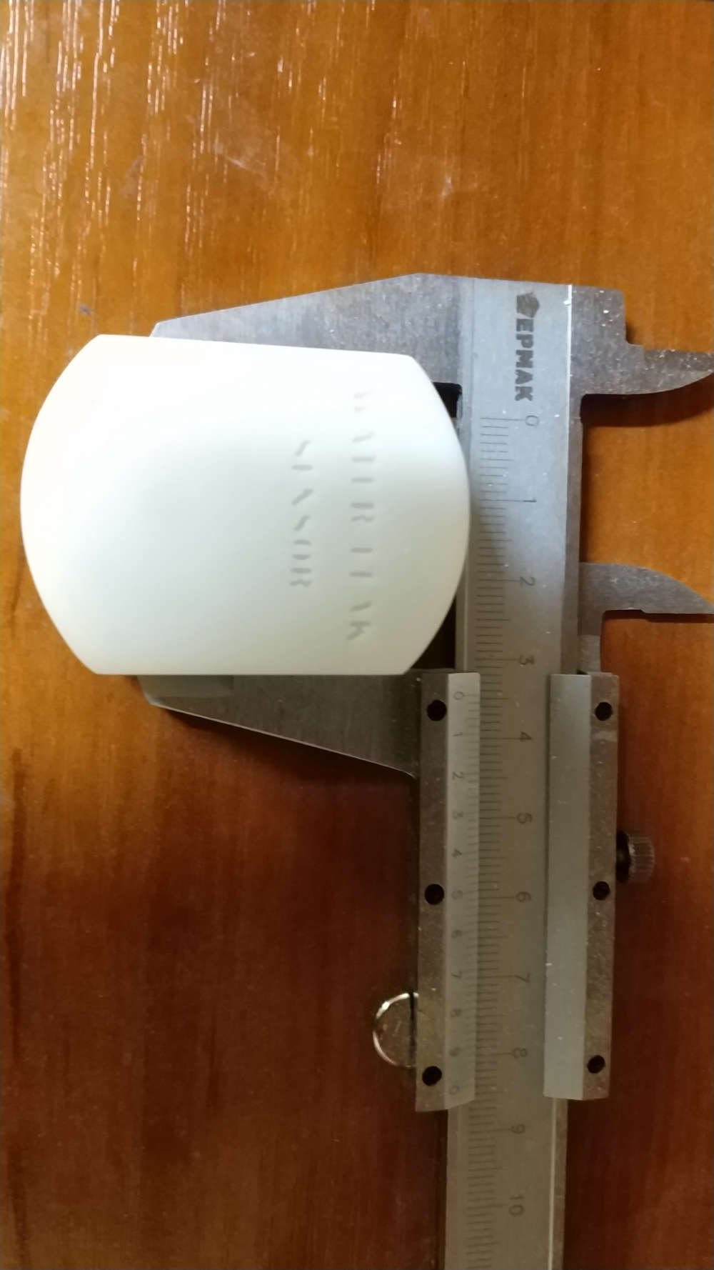
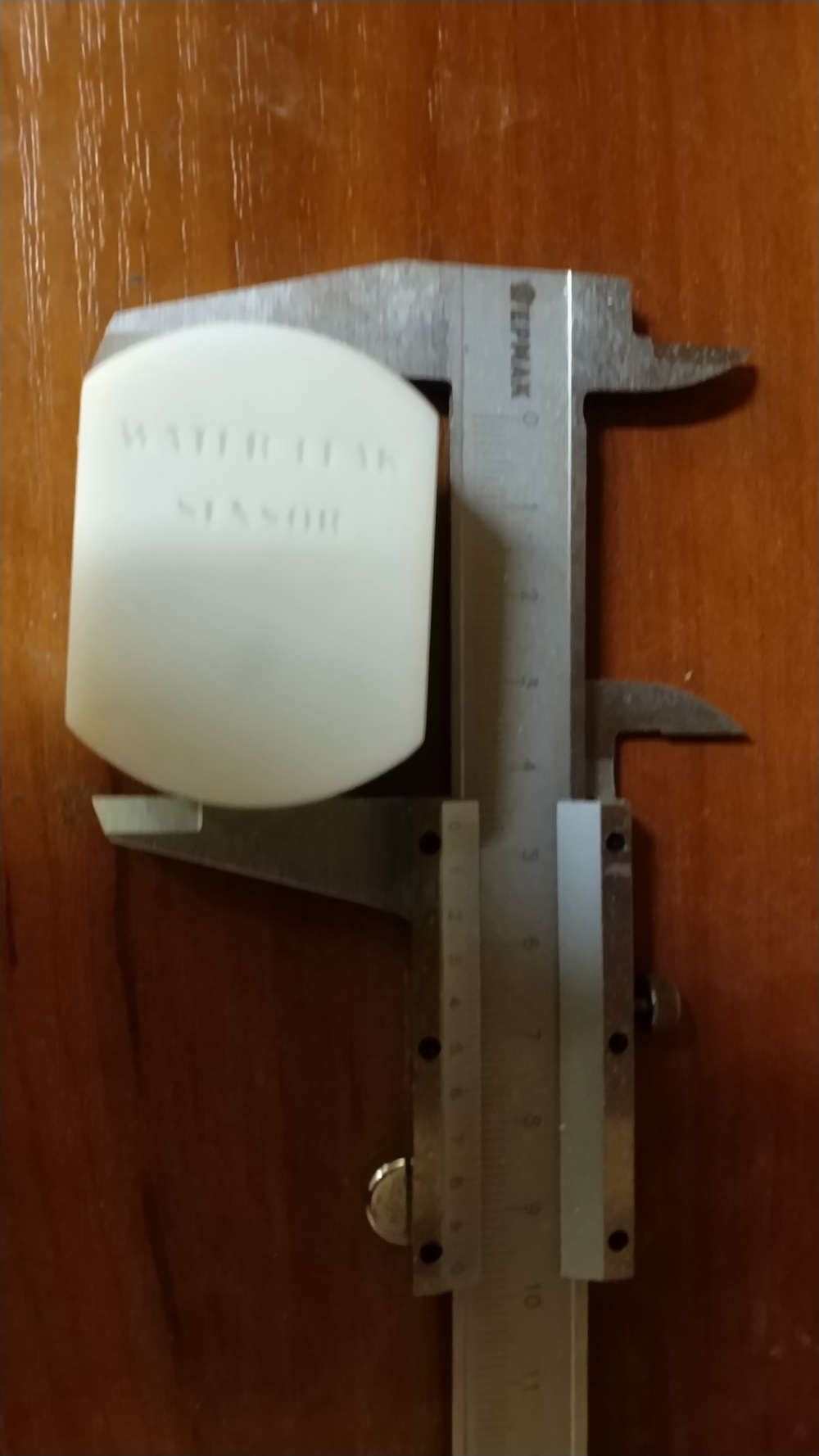
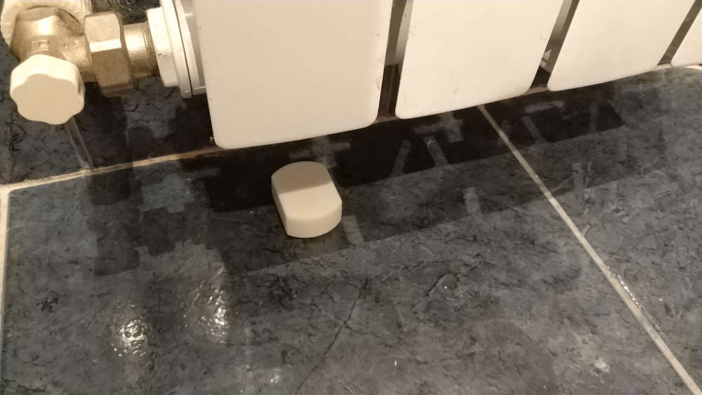
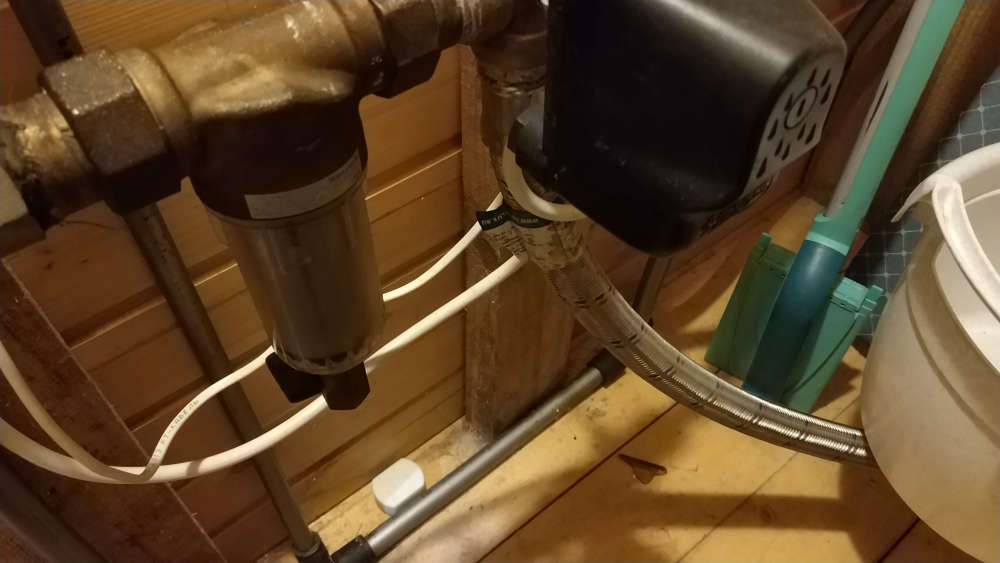
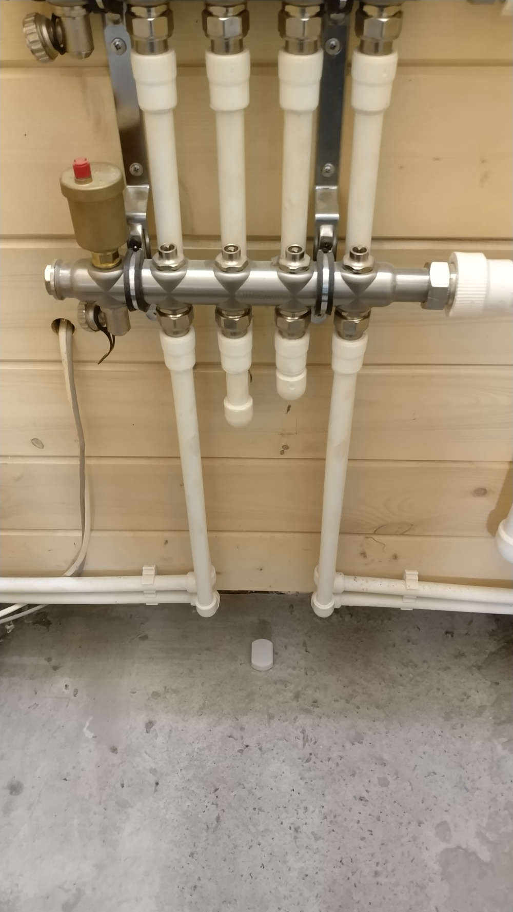
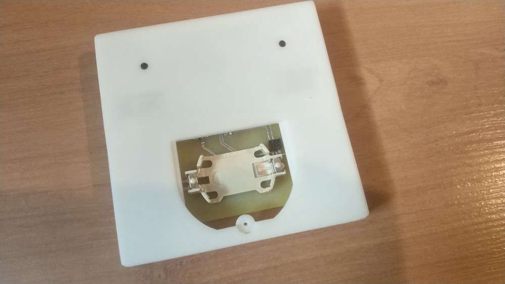
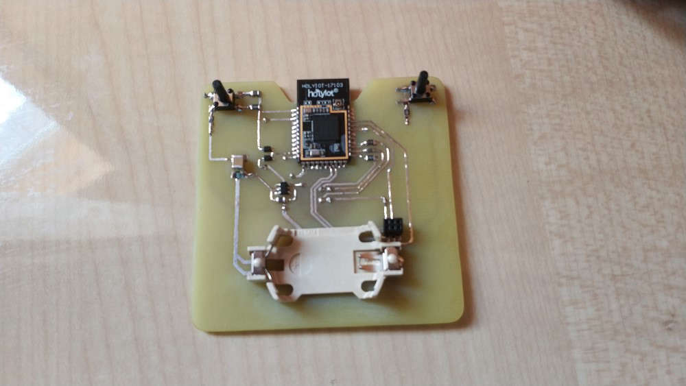
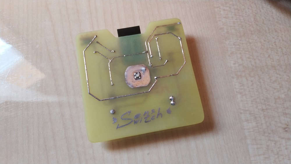
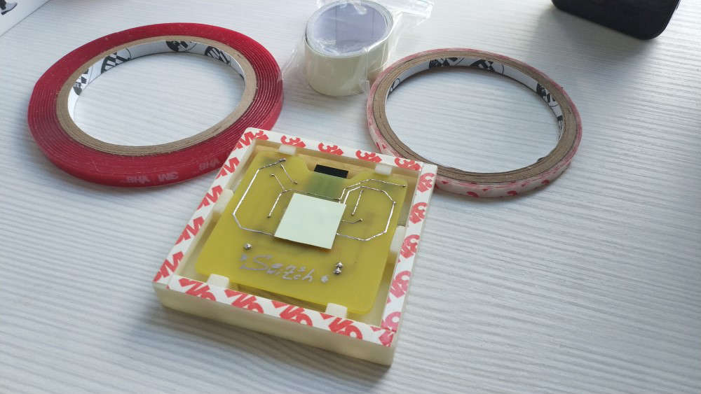
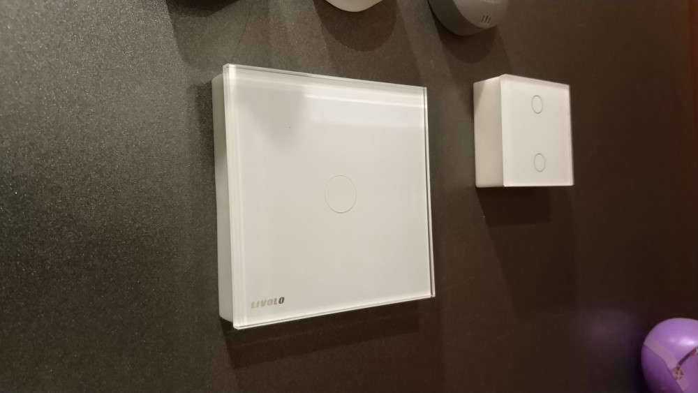
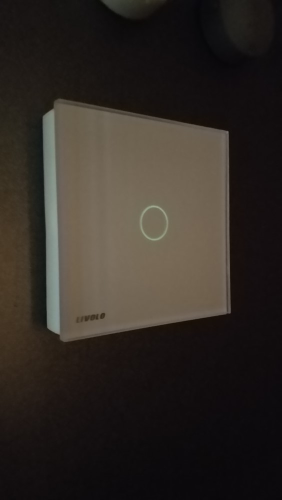
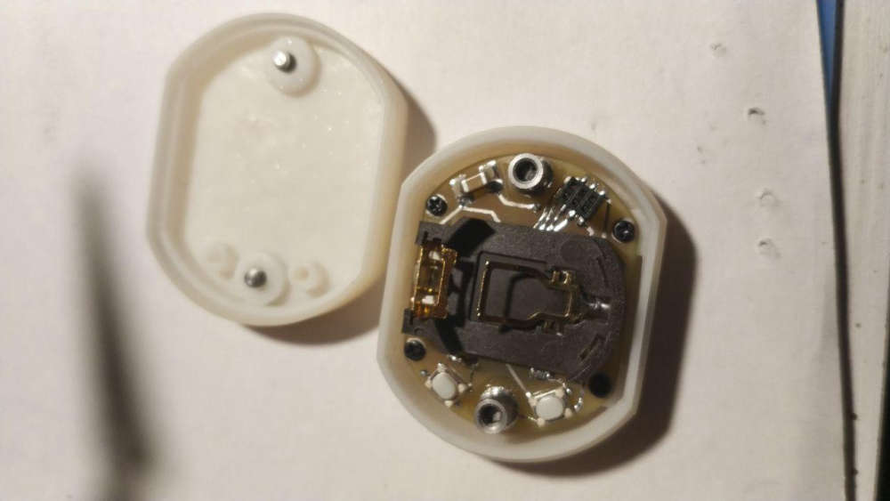
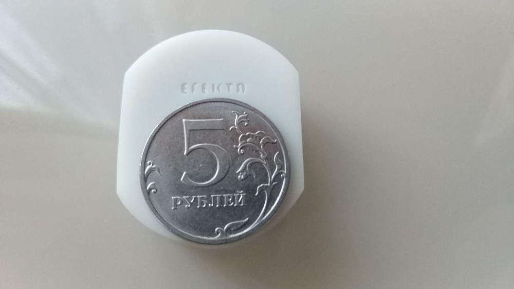
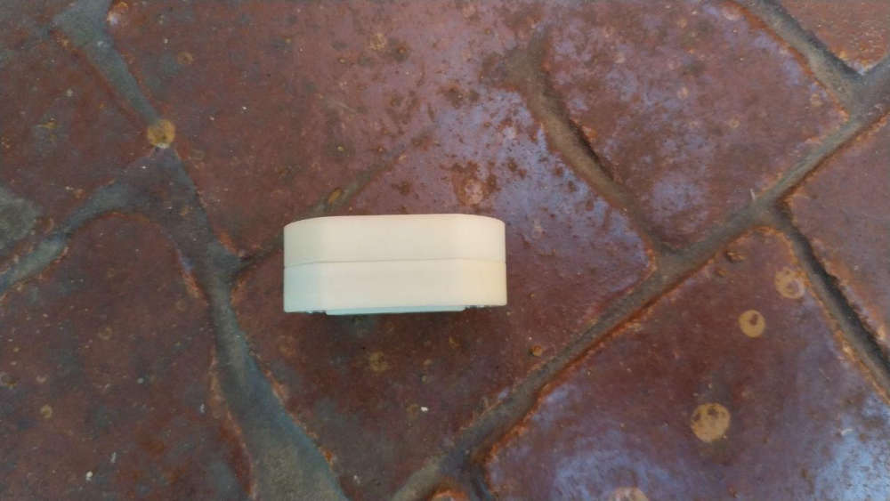
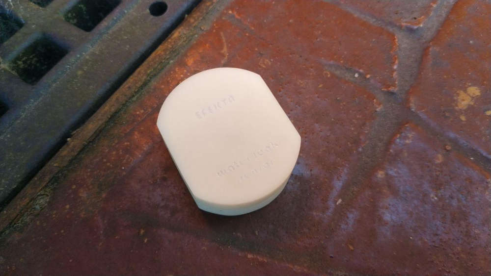
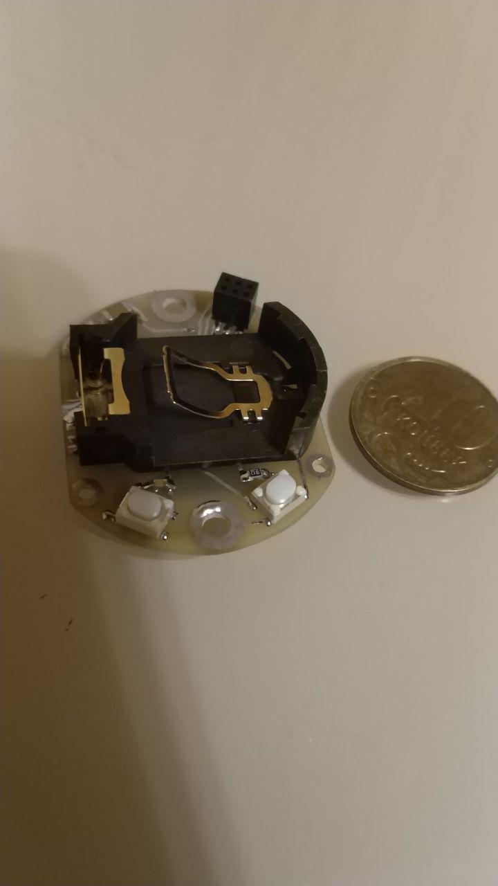
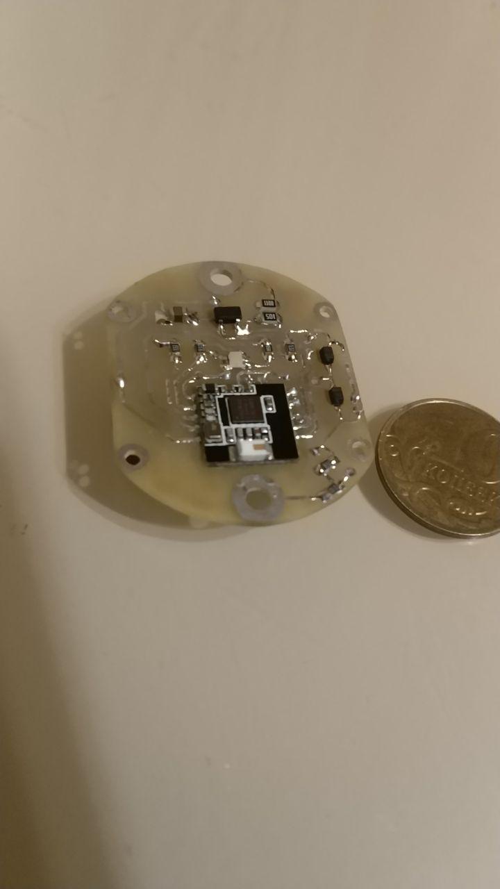
Pro version of water leak sensor, for very very hard to reach and remote places :). Version with amplifier.

-
@berkseo what's the range improvement with amplifier ?
From my experience with nrf24 the amplifier + ceramic antenna was not giving great results.@nca78 said in What did you build today (Pictures) ?:
what's the range improvement with amplifier ?
From my experience with nrf24 the amplifier + ceramic antenna was not giving great results.A few months ago, when testing, I received about 200 meters of stabilized power from the power bank. While this device was tested for 30 metres. There are problems with receiving the delivery confirmation, the device is guaranteed to transmit, but does not receive the delivery confirmation(sometimes). I think it's linked to my gateway, it has the usual radio module nrf24l01+. Of course we are talking about dc-dc-mode :)
-
Pro version of water leak sensor, for very very hard to reach and remote places :). Version with amplifier.
I do not want to be too offensive, but it seems to me as if your skills in electronics and 3D-printing is way better developed than your trust in the plumbing :sweat_smile:
Now for the serious part: how often do you experience water leaks? And how long do the batteries in this design last?
Boozz
-
I do not want to be too offensive, but it seems to me as if your skills in electronics and 3D-printing is way better developed than your trust in the plumbing :sweat_smile:
Now for the serious part: how often do you experience water leaks? And how long do the batteries in this design last?
Boozz
-
@gohan
I was referring to @berkseo 's situation and images/examples. I just wondered why this person would put this amount of effort in creating a device that would probably not be functional at the moment it should be functional. I'm just thinking about corrosion of the pcb, a drained battery, change of properties of the 'sensor' due to time-effects etc.
Do not misunderstand me: I'm absolutely enthousiastic about this device (and I'm impressed by how small it is and the design), but I'm a bit concerned about the effects that could negatively affect the behaviour of it. -
@gohan
I was referring to @berkseo 's situation and images/examples. I just wondered why this person would put this amount of effort in creating a device that would probably not be functional at the moment it should be functional. I'm just thinking about corrosion of the pcb, a drained battery, change of properties of the 'sensor' due to time-effects etc.
Do not misunderstand me: I'm absolutely enthousiastic about this device (and I'm impressed by how small it is and the design), but I'm a bit concerned about the effects that could negatively affect the behaviour of it.@boozz said in What did you build today (Pictures) ?:
@gohan
I was referring to @berkseo 's situation and images/examples. I just wondered why this person would put this amount of effort in creating a device that would probably not be functional at the moment it should be functional. I'm just thinking about corrosion of the pcb, a drained battery, change of properties of the 'sensor' due to time-effects etc.
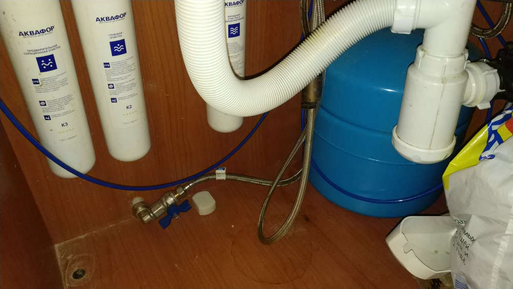
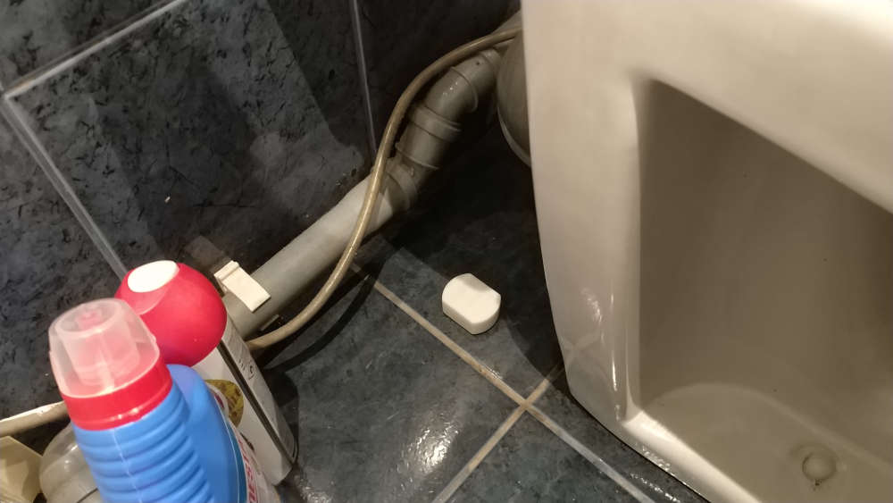
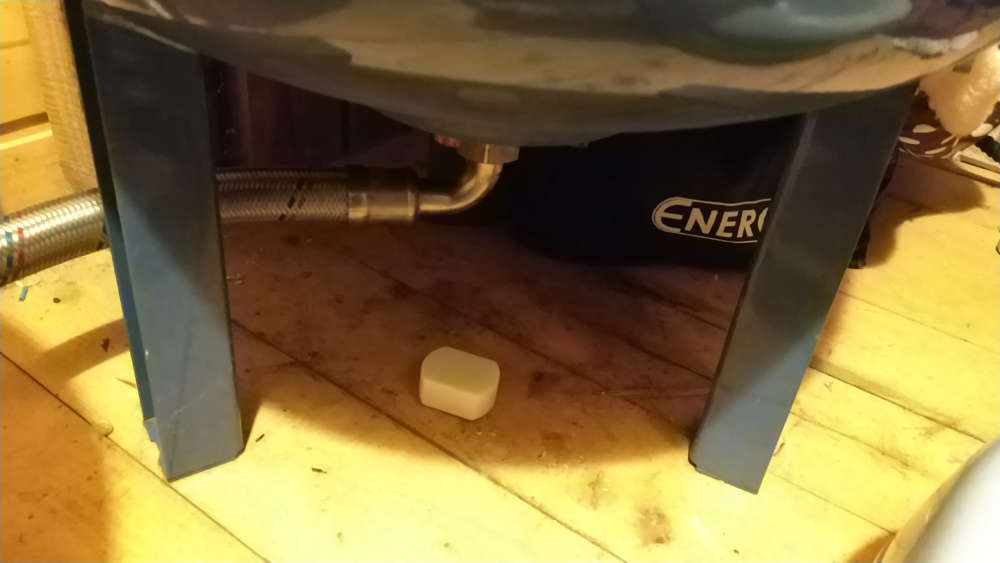
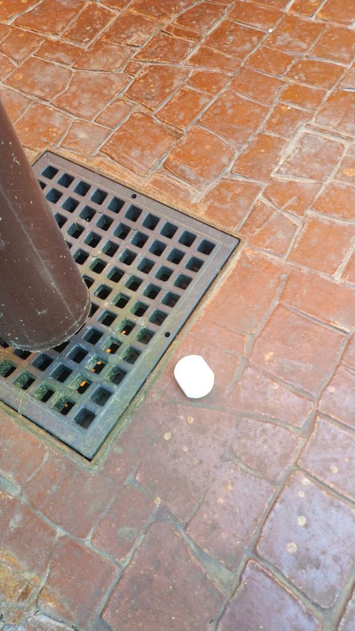
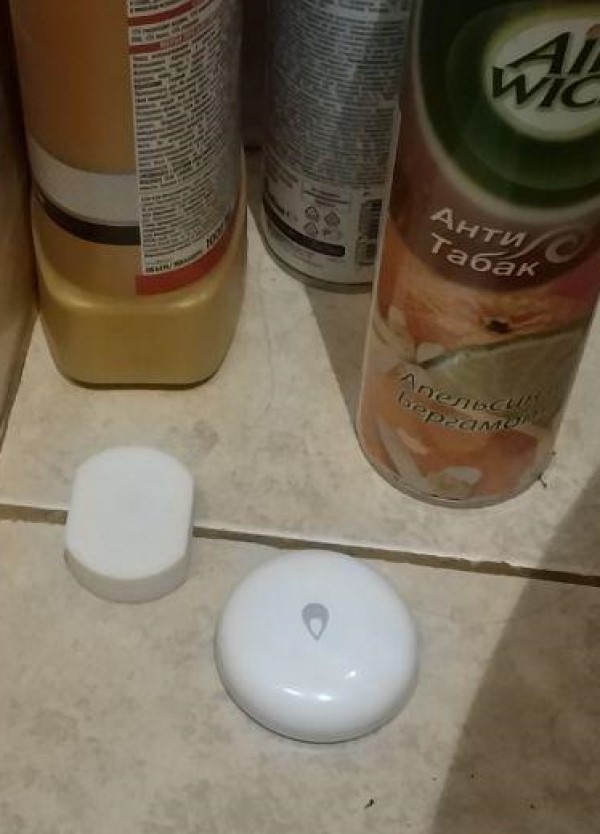
Do not misunderstand me: I'm absolutely enthousiastic about this device (and I'm impressed by how small it is and the design), but I'm a bit concerned about the effects that could negatively affect the behaviour of it.You can see on the picture he already had a leak under his kitchen sink :p
And in some countries pipes installations are not very reliable, for example yesterday evening my dishwasher emptied on the floor because the workers did not glue the PVC pipe angle so it went away. Would have love to be warned at the first drops instead of realizing it much later when walking in water in the middle of the kitchen. I also had problem with drinkable water fountain not stopping when tank was full and emptying the 20l bottle on the floor, leaks of sinks and bathtub in the bathrooms in previous apartment, etc etc
So there's truly a "market" for those sensors, they could also be slightly modified to make rain detection instead and warn you if rain is coming and some windows are still opened (very useful here in tropical weather when you can switch from sunny to tropical rain in a mater of minutes).And if you use the low power comparator of the nrf5 it uses only a few uA in sleep mode, easily detects a bit of water between the 2 contacts and can last for 1-2 years on button cell.
-
@boozz said in What did you build today (Pictures) ?:
@gohan
I was referring to @berkseo 's situation and images/examples. I just wondered why this person would put this amount of effort in creating a device that would probably not be functional at the moment it should be functional. I'm just thinking about corrosion of the pcb, a drained battery, change of properties of the 'sensor' due to time-effects etc.
Do not misunderstand me: I'm absolutely enthousiastic about this device (and I'm impressed by how small it is and the design), but I'm a bit concerned about the effects that could negatively affect the behaviour of it.You can see on the picture he already had a leak under his kitchen sink :p
And in some countries pipes installations are not very reliable, for example yesterday evening my dishwasher emptied on the floor because the workers did not glue the PVC pipe angle so it went away. Would have love to be warned at the first drops instead of realizing it much later when walking in water in the middle of the kitchen. I also had problem with drinkable water fountain not stopping when tank was full and emptying the 20l bottle on the floor, leaks of sinks and bathtub in the bathrooms in previous apartment, etc etc
So there's truly a "market" for those sensors, they could also be slightly modified to make rain detection instead and warn you if rain is coming and some windows are still opened (very useful here in tropical weather when you can switch from sunny to tropical rain in a mater of minutes).And if you use the low power comparator of the nrf5 it uses only a few uA in sleep mode, easily detects a bit of water between the 2 contacts and can last for 1-2 years on button cell.
@nca78 I suspect what @boozz is referring to is not the functionality but the direct effect of water on the device.
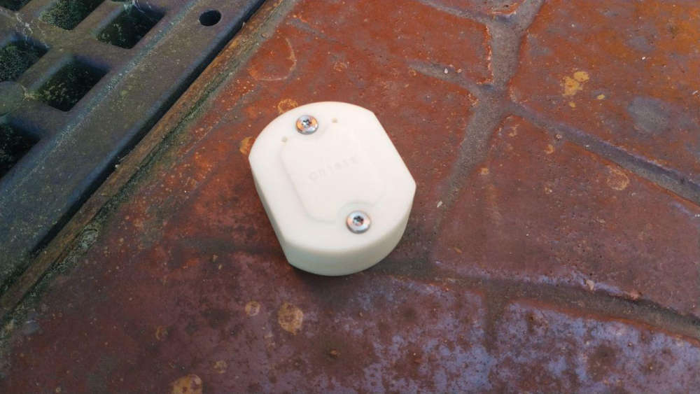
Pretty sure a pair of threaded socket bolts could be swapped for the cover screws and permit wall mounting on a couple of threaded SS electrodes to solve it though, and it would still make for a very compact and unobtrusive arrangement. -
I think very useful device.
Stainless screw like detectors - no corrosion.
And all the time this device sits in dry area - no corrosion.
But software must call controller ( with battery level for example ) sometimes, say one per a day, to inform it is alive.
And if controller does not receive this message - sends alert.
I am using this for all my nodes - very easy in Domoticz.
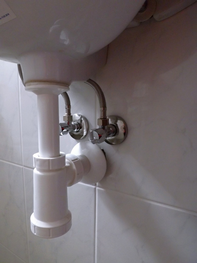
If node dies, Domoticz send me e-mail ( and SMS ) with information.And 40 years with this hoses for example ?
Try it .....
-
I think very useful device.
Stainless screw like detectors - no corrosion.
And all the time this device sits in dry area - no corrosion.
But software must call controller ( with battery level for example ) sometimes, say one per a day, to inform it is alive.
And if controller does not receive this message - sends alert.
I am using this for all my nodes - very easy in Domoticz.
If node dies, Domoticz send me e-mail ( and SMS ) with information.And 40 years with this hoses for example ?
Try it .....
@kimot I followed your logic until you suggested 40 years in the future with presumably failed wash hand basin umbillicals..

Hello! It looks like you're interested in this conversation, but you don't have an account yet.
Getting fed up of having to scroll through the same posts each visit? When you register for an account, you'll always come back to exactly where you were before, and choose to be notified of new replies (either via email, or push notification). You'll also be able to save bookmarks and upvote posts to show your appreciation to other community members.
With your input, this post could be even better 💗
Register Login