šŸ’¬ NRF2RFM69


  • Admin

    use a 4.7uF capacitor, or there about..

    There is no pads for a SMA connector, but you could attach one with a pigtail..


  • @tbowmo Thanks for the Information... One stupid question about the SMA conenctor šŸ™‚ Is it enough to connect only the Antenna Output conenction or must GND also conencted...?


  • Mod

    You can just solder the antenna only on pcb. I use a coil spring type


  • just one more question... I have on the Gateway a RFM69HW and a node with a RFM69W module. In the Gateway Sketch is the HW type enabled

    #define MY_RFM69_FREQUENCY RF69_868MHZ
    #define MY_IS_RFM69HW
    

    But there is no comunication from the node... I use Mysensors 2.1.1.
    Any idea?


  • Mod

    What gateway is that? I'd suggest to try mysensors 2.2 development


  • @gohan It at the Moment only a test. So I have one EasyPCB NRF board with FTDI as Gateway and another EasyPCB board with DHT22 Sensor attached as Node. On both is a 4,7uF electrolytic condensator attached Close to the NRF socket. Both boards are at the Moment with RFM69W 868. The sensor node is battey powered.


  • Mod

    Get latest 2.2 library and use new rfm69 driver. Did you remember to close the IRQ contact in the easypcb?


  • @gohan Oh Sh* must check this... I've tried it yesterday on both devices the 2.2 Dev. But will Keep ypu informed...
    Don't find the jumperfor the IRQ on the Rev 9 board. can you please post a Picture. Seems that this one is definitly not closed...
    --> Edit... found it in the documentation but still the same.
    Think the next Point to check for me are the antennas... šŸ˜ž


  • Mod

    I'd suggest to buy the coil spring antennas for your frequency, they are cheap and compact.


  • in principle there is traffic between node and Gateway..

    159631 !TSM:FPAR:NO REPLY
    159637 TSM:FPAR
    169848 TSF:MSG:SEND,10-10-255-255,s=255,c=3,t=7,pt=0,l=0,sg=0,ft=0,st=OK:
    171868 !TSM:FPAR:NO REPLY
    171874 TSM:FPAR
    179087 TSF:MSG:SEND,10-10-255-255,s=255,c=3,t=7,pt=0,l=0,sg=0,ft=0,st=OK:
    181106 !TSM:FPAR:FAIL
    181112 TSM:FAIL:CNT=4
    181118 TSM:FAIL:DIS
    181123 TSF:TDI:TSL
    191131 TSM:FAIL:RE-INIT
    191137 TSM:INIT
    191143 TSM:INIT:TSP OK
    191150 TSM:INIT:STATID=10
    191158 TSF:SID:OK,ID=10
    191164 TSM:FPAR
    198377 TSF:MSG:SEND,10-10-255-255,s=255,c=3,t=7,pt=0,l=0,sg=0,ft=0,st=OK:
    200396 !TSM:FPAR:NO REPLY
    200402 TSM:FPAR
    207616 TSF:MSG:SEND,10-10-255-255,s=255,c=3,t=7,pt=0,l=0,sg=0,ft=0,st=OK:
    209635 !TSM:FPAR:NO REPLY
    209641 TSM:FPAR
    216854 TSF:MSG:SEND,10-10-255-255,s=255,c=3,t=7,pt=0,l=0,sg=0,ft=0,st=OK:
    218873 !TSM:FPAR:NO REPLY
    218880 TSM:FPAR
    226093 TSF:MSG:SEND,10-10-255-255,s=255,c=3,t=7,pt=0,l=0,sg=0,ft=0,st=OK:
    228112 !TSM:FPAR:FAIL
    228118 TSM:FAIL:CNT=5
    228124 TSM:FAIL:DIS
    228128 TSF:TDI:TSL
    238135 TSM:FAIL:RE-INIT
    238141 TSM:INIT
    238147 TSM:INIT:TSP OK
    238153 TSM:INIT:STATID=10
    238161 TSF:SID:OK,ID=10
    238168 TSM:FPAR
    248385 TSF:MSG:SEND,10-10-255-255,s=255,c=3,t=7,pt=0,l=0,sg=0,ft=0,st=OK:
    250404 !TSM:FPAR:NO REPLY
    250411 TSM:FPAR
    257624 TSF:MSG:SEND,10-10-255-255,s=255,c=3,t=7,pt=0,l=0,sg=0,ft=0,st=OK:
    259643 !TSM:FPAR:NO REPLY
    259649 TSM:FPAR
    269731 TSF:MSG:SEND,10-10-255-255,s=255,c=3,t=7,pt=0,l=0,sg=0,ft=0,st=OK:
    271751 !TSM:FPAR:NO REPLY
    271757 TSM:FPAR
    
    
    0;255;3;0;9;189196 TSF:PNG:SEND,TO=0
    0;255;3;0;9;189206 TSF:CKU:OK
    0;255;3;0;9;189214 TSF:MSG:GWL OK
    0;255;3;0;9;191236 !TSF:MSG:SEND,0-0-10-10,s=255,c=3,t=8,pt=1,l=1,sg=0,ft=0,st=NACK:0
    0;255;3;0;9;244555 TSF:MSG:READ,10-10-255,s=255,c=3,t=7,pt=0,l=0,sg=0:
    0;255;3;0;9;244574 TSF:MSG:BC
    0;255;3;0;9;244582 TSF:MSG:FPAR REQ,ID=10
    0;255;3;0;9;244594 TSF:PNG:SEND,TO=0
    0;255;3;0;9;244604 TSF:CKU:OK
    0;255;3;0;9;244613 TSF:MSG:GWL OK
    0;255;3;0;9;257744 !TSF:MSG:SEND,0-0-10-10,s=255,c=3,t=8,pt=1,l=1,sg=0,ft=0,st=NACK:0
    0;255;3;0;9;269957 TSF:MSG:READ,10-10-255,s=255,c=3,t=7,pt=0,l=0,sg=0:
    0;255;3;0;9;269977 TSF:MSG:BC
    0;255;3;0;9;269985 TSF:MSG:FPAR REQ,ID=10
    0;255;3;0;9;269996 TSF:PNG:SEND,TO=0
    0;255;3;0;9;270006 TSF:CKU:OK
    0;255;3;0;9;270014 TSF:MSG:GWL OK
    0;255;3;0;9;281585 !TSF:MSG:SEND,0-0-10-10,s=255,c=3,t=8,pt=1,l=1,sg=0,ft=0,st=NACK:0
    0;255;3;0;9;289732 TSF:MSG:READ,10-10-255,s=255,c=3,t=7,pt=0,l=0,sg=0:
    0;255;3;0;9;289753 TSF:MSG:BC
    0;255;3;0;9;289761 TSF:MSG:FPAR REQ,ID=10
    0;255;3;0;9;289771 TSF:PNG:SEND,TO=0
    0;255;3;0;9;289781 TSF:CKU:OK
    0;255;3;0;9;289789 TSF:MSG:GWL OK
    0;255;3;0;9;297015 !TSF:MSG:SEND,0-0-10-10,s=255,c=3,t=8,pt=1,l=1,sg=0,ft=0,st=NACK:0
    0;255;3;0;9;306757 TSF:MSG:READ,10-10-255,s=255,c=3,t=7,pt=0,l=0,sg=0:
    0;255;3;0;9;306776 TSF:MSG:BC
    0;255;3;0;9;306784 TSF:MSG:FPAR REQ,ID=10
    0;255;3;0;9;306796 TSF:PNG:SEND,TO=0
    0;255;3;0;9;306806 TSF:CKU:OK
    0;255;3;0;9;306814 TSF:MSG:GWL OK
    0;255;3;0;9;316682 !TSF:MSG:SEND,0-0-10-10,s=255,c=3,t=8,pt=1,l=1,sg=0,ft=0,st=NACK:0
    0;255;3;0;9;322084 TSF:MSG:READ,10-10-255,s=255,c=3,t=7,pt=0,l=0,sg=0:
    0;255;3;0;9;322103 TSF:MSG:BC
    0;255;3;0;9;322111 TSF:MSG:FPAR REQ,ID=10
    0;255;3;0;9;322123 TSF:PNG:SEND,TO=0
    0;255;3;0;9;322131 TSF:CKU:OK
    0;255;3;0;9;322142 TSF:MSG:GWL OK
    0;255;3;0;9;333180 !TSF:MSG:SEND,0-0-10-10,s=255,c=3,t=8,pt=1,l=1,sg=0,ft=0,st=NACK:0


  • Mod

    That's either the node not receiving or the gateway having problems when sending


  • @gohan šŸ˜ž any idea what else I can do/check ?


  • @Markus. You have an RF issue. Typically for nrf24l01+ I'd use a different power supply or a different module.

    Are you sure both modules are set to the same channel and frequency? What antennas are you using?
    Do you have HW modules?


  • @alexsh1 I use at the Moment RFm69W 868 modules not NRF. Because the RFMs are mounted on the NRF connector on an EasyPCB. I use at the Moment single wire antennas with a lenght of 8,3 cm.


  • @Markus and channel and freq? are they the same in your sketch?


  • @alexsh1 should be, becaus ist not defined explicit in the Sketch. By Default in the MYS Lib 2.2 dev is it 868 mhz. And when i try to define the frequency in the Sketch. Like #define MY_RFM69_FREQUENCY RF69_868MHZ
    I get the error message. 'RF69_868MHZ' was not declared in this scope


  • Mod

    @Markus. try RFM69_868MHZ (RF69 -> RFM69)


  • @mfalkvidd you are right... Ist now added in the GW and node Sketch, but still the same Problem.


  • I think at the end will it be a power problem. It seems that the sensor node powered with 2x AA cells can not handle the Radio on TX/RX. The same on the Gateway site which is also a Easy PBB powered fom the FTDI Connector connected to USB. The question now is how can i fix this power Problems ? Or more, how can i make sure that this is definitly not the reason.


  • Mod

    Try bigger capacitor


  • @gohan 10uF electrolyt cap direct on the radios already tierd beside the 4,7uF on the Radio socket.


  • @gohan ohhhh helllll... its working.. As usual.. the Problem was infront of the Monitor... šŸ™‚ So, two Problems. the first mistake i did was to use a HW module as Gateway. The power source was a FTDI adaptor which has only max Output current of 50mA (HW module Needs 120mA Minimum). The result was randomly reboot of the Gateway. The second and main Problem was the Jumper of the IRQ on the Easy PCB boards. I checked only the domumentation and there is the Jumper wrong descriped. So i placed the Jumper wrong. I have corrected this now on my two test boards and use a W module on the Gateway.. now its working šŸ™‚
    Many thanks for all the Patience... šŸ™‚


  • Mod

    @Markus. said in šŸ’¬ NRF2RFM69:

    I checked only the domumentation and there is the Jumper wrong descriped

    Where is it wrong described?


  • @gohan the arrow goes to the Jumper close to the cap on the NRF socket.
    [link text]https://www.openhardware.io/view/4/EasyNewbie-PCB-for-MySensors(link url)
    But the other Jumper isthe right one . Well, could be also wrong interpreted frommy site, however ist now working and the range is also fine so far...


  • Mod

    you are right, the picture has an error, but the pcb has the right labels. Maybe @sundberg84 may fix the picture šŸ™‚


  • @gohan yes and i didn't checked the PCB Label...shit happends


  • Hardware Contributor

    @Markus. Sorry, this is because it was changed from Rev 8 to Rev 9 and the location of the IRQ jumper is changed. I will try to update to REV 9 pictures only.


  • @tbowmo

    @tbowmo said in šŸ’¬ NRF2RFM69:

    I've added the panel design to dirtypcb's store.. So just order it from the following link

    http://dirtypcbs.com/view.php?share=16378&accesskey=4e199dccdf623eab0c90fddbc4786f80

    I ordered PCBs from dirtypcbs via the link above. But just now I got this message from dirtypcb:
    "Problems Drill holes don't match with the solder pads."
    Do you know why?

    Thanks for your help!


  • Mod

    I got them from seeed studio, no problem


  • @gohan But then I guess you didn't use the panel version?
    From what I can see it looks like the drill file in the panel version is missing the drill holes on the board itself. It looks like it only contains the drill holes between the cards? I am not sure, and has little experience with drill files and pcb design, but it looks like this when I open the drill file (and the profile layer, .gml-file) in gerbview in kicad:
    0_1516022887876_de7ec221-3c6f-4fba-ba8f-def608ce3788-image.png

    From what I can see the drill holes on the boards itself is missing, but I guess there are others that have ordered this panel version from dirtypcbs, so I find it strange that there should be an error.


  • Admin

    @jostor

    That sounds weird, as I haven't touched the files at dirtypcb for the last couple of years.. And I got a notification from dirtypcb the other day, that another set was successfully ordered..

    Perhaps it's a fluke in their system?


  • @tbowmo
    OK. Then I guess the files are OK, and that the error is in dirtypcb's system. Thanks!
    But what about the drill file on your github. Why am I not seeing the drill holes on the card itself when I am opening it? Shouldn't they be a part of the drill file?


  • Admin

    @jostor

    probably.. Can't remember much of what I did 2 years ago šŸ™‚


  • @tbowmo
    That's understandable šŸ™‚

    I received this email from dirtypcbs today:

    "Thanks for ordering!
    So here is the thing- please see attached screenshots. The only drill holes in this Gerber are the mouse bits(the pink layer, photo 001). The light green layer(photo 002) is the top solder mask layer. The problem is that no drills are specified in the solder pads or circles, which means that if we make the board exactly how the gerber is designed, all of the light green parts are solder pads and there WILL NOT be drill holes at the bottom of the solder pads, which seems wrong.
    I checked this gerber in our system, and I couldn't find any other orders that included it. Even if we have made this board for other people, it doesn't mean that this back-and-forth didn't happen before. I suggest that you write the designer and forward this message and screenshot to him, so that he can update the design in case you order again in the future.
    I am also going to include a screenshot of the whole design, and I hope that will be clear to you what the problem is.
    "

    The attachments in the email are basically showing the same as the image I attached in my post above.
    I don't find any design files for the panel layout in your git repository, just gerber files. I guess you don't have them anymore?
    I will try to make a new panel layout myself, if I not succeed, I will just order single boards.


  • Admin

    @jostor

    If I remember right I used this gerber panelizer to place 3 of the normal gerber files on one board. You could do the same again, and re-create a panel.


  • @tbowmo
    Thanks! I have looked at it, and it seems easy to create a panel with that tool. I will look more into it later today or tomorrow.


  • Hi,
    I ordered this board trough pcbway on 6th december and still didn't received it. I event did not received any confirmation email accept paypal payment confirmation. Did any one here ordered those boards with pcbway ? Do they send any information about the order ?


  • Admin

    @rozpruwacz, I'll PM you the shipping details.


  • What value should be the C1 SMD ? I don't have kicad, so I can't open the file. Just saw it the 3d sketch and realized I have to order some SMDs...


  • @joaoabs i use 10u and ir works ok.


  • Admin

    @joaoabs

    It's not a specific value.. I just added the footprint, so that it was available, if someone wanted to add a capacitor.


  • First of all, thank you to the creator of this very convenient PCB.
    I ordered 10 of those but got confused when I tried to make a RPi 3 gateway and Arduino node.

    In the "Connecting the Radio" guide, the instructions are to connect NRF's IRQ pin to Arduino No 2 pin.
    This is where RFM's D100 pin is supposed to be connected. As far as I could tell from the PCB this is correct, as RFM's D100 pin is broken out to where NRF's IRQ pin is.

    However, in the "Building a Raspberry Pi Gateway" guide, it says to connect RFM's D100 pin to RPi's pin 22, which is where NRF's CE pin is supposed to be connected, not IRQ. As for IRQ, it says it's "optional", but if you do connect it, this should be to RPi's pin 15.

    So, if you connect the radio to the RPi following the NRF instructions, you get a different circuit than if you connect it following the RFM instructions (and using the pin matching you get from the "connecting the radio" guide). When I did the former, the gateway wasn't working, but when I did the latter, it worked.

    I don't know why this difference exists, but I think it's important to point out for anyone wanting to use the PCB with an RPi.


  • @symos IRQ is not utilised for nrf24l01+ in MySensors. There is a provision for future, but just ignore IRQ for now.


  • Admin

    @alexsh1

    You can enable interrupt usage for NRF24, depending on your hardware and needs.

    see the #MY_RF24_IRQ_PIN define, which is used around here


  • Mod

    see the #MY_RF24_IRQ_PIN define, which is used around here

    Or the documentation at https://www.mysensors.org/apidocs/group__RF24SettingGrpPub.html#ga23c9926f77307bf1b0263432232e4f4a šŸ˜‰


  • @tbowmo I wonder what would be an example of using it?!
    I knew it would be supported at a certain time in the future but I did not realise it it supported already.


  • On a related note, if anyone is trying to get the NRF2RFM69 board or similar working with the awesome Sensebender Gateway and W5100 Ethernet board, hereā€™s what I had to do today as far as the CS and IRQ defines are concerned.

    [FYI: Iā€™m coming back to MySensors after a long hiatus and am in the process of updating (some from v1.3!) all my gateways and sensors...]

    Aside from the usual radio selection, I had use the new driver and point the RFM69 NSS and IRQ pins at the nRF CS and IRQ nets. Also, if you want to, you can point the RFM69 RESET pin at the nRF CE net:

    #define MY_RFM69_NEW_DRIVER
    #define MY_RF69_RESET 34  // Note: Should be MY_RFM69_RST_PIN, but this didnā€™t work.
    #define MY_RFM69_IRQ_PIN 31
    #define MY_RFM69_IRQ_NUM digitalPinToInterrupt(MY_RFM69_IRQ_PIN)
    #define MY_RFM69_CS_PIN 29
    #define MY_DEBUG_VERBOSE_RFM69  // Note: Only if you want to check the pins, RSSI, etc.
    

    0_1547615836181_MySensors Gateway & Nodes - Small.jpg

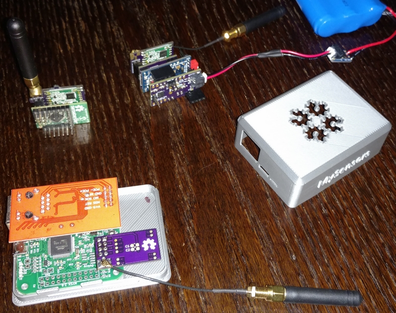
    Hope that helps someone.


  • Admin

    @acb

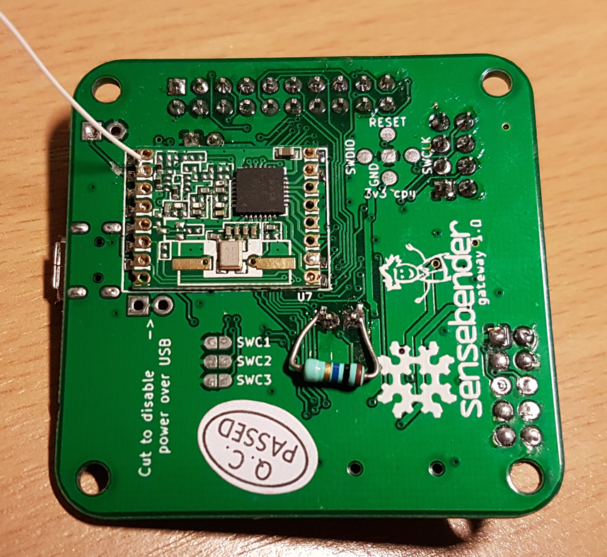
    You do know that there is solder pads for RFM69HW on the back of the gateway, right? And the board defs for the gateway are configured to use those pins for the RFM69 by default.


  • Mod

    Adding image for reference
    alt text


  • @alexsh1 Thanks, though I'm not sure you understood exactly what I'm saying.
    If I connect the radio to the RPi 3 following the NRF instructions and using the NRF2RFM69 adapter, it is NOT working.

    For it to work, I MUST connect the "IRQ" pin of the NRF2RFM69 (which corresponds to RFM's D100 pin) to RPi's pin 22 (which is where CE is supposed to go, according to instructions) and leave CE unconnected.

    So if someone is using the NRF2RFM69 adapter and tries to connect the radio to the RPi 3 as if it were an NRF, it won't work. I think this is confusing and that's why I posted it.


  • Yes @tbowmo, I saw the solder pads on the back - although thanks for the reminder (and image @mfalkvidd)!

    Iā€™m not using those (yet) since I didnā€™t want to ā€œpermanentlyā€ attach one of my ā€œpreciousā€ RFM69HWs to it whilst Iā€™m tinkering with all these lovely new radios you now support. RFM95 next I hope, after checking out the FOTA and signing! You guys have really done great work!

    I also wanted to range-test with a few different externally mounted antennas I had lying around and so I combined pads for a surface mount U.fl and edge SMA on my own NRF2RFM69.

    Not a great deal of room around the SBGWā€™s pin breakout (P1) for a helical - although I really respect the design choices - so I figure Iā€™ll probably breakout those pins to pigtail an SMA.

    But this is getting a bit off-topic Re: NRF2RFM69 and probably better suited to the Sensebender Gateway thread.

    Bringing it back on-topic a little:

    Do you know if there is a version of this board that is pad-compatible with the C-versions of these HopeRF RFM69s before I go searching? (Since I believe the C-versions are also pad-compatible with the RFM95sā€¦)


  • Banned

    This post is deleted!


  • @acb
    Hi @acb and others, regarding "Do you know if there is a version of this board that is pad-compatible with the C-versions of these HopeRF RFM69s before I go searching? (Since I believe the C-versions are also pad-compatible with the RFM95sā€¦)" - did you find any alternative?
    I'm in the same boat looking for an adapter from NRF24 to the footprint of RFM69*C = RFM95/96.
    Thanks, Joost


Suggested Topics

1
Online

11.2k
Users

11.1k
Topics

112.5k
Posts