💬 Smart Alarm Clock


  • Admin

    Cool project!


  • @hek
    Thanks!!!

    I've been stalking the forum and asking beginner questions for at least a year now... I've learned so much and am so grateful for everyone's help... Now I've finally got a project close to completion, so I thought it was about time to try and give back 🙂

    Plus by sharing, the super smart forum members like yourself will probably tell me where I messed and could have done better... lol


  • Admin

    We don't have anything similar in build pages on the main site. I'll add your project there as well.

    You have a long list of features, will be interesting to follow!


  • @hek
    thanks!!!!

    I've got a bunch of other things I want to add to it...

    I'm really excited about adding @petewill 's Bed-Occupancy-Sensor... I've got two kids (and I'm planning on building them both a clock)... and they are at my house 50% of the time... so I want the alarms to go off on school days, but only when they are at my house.

    So I plan on using the bed occupancy sensor to cancel the alarm if no one is in the bed.

    On the flip side, if the kid turns off the alarm, but doesn't get out of bed within a set amount of time, I want the alarm to go off again... kinda like a forced snooze.

    I also want to add an SD card and mini amplifier (LM386) so I can play their favorite song as the wake-up music... but I've got to wait for my aliexpress order of the LM386 to arrive (in 30 to 60 days...lol)


  • Admin

    Haha, evil father 😉 The kids will probably outsmart you somehow.


  • @hek

    I welcome the challenge 🙂


  • Admin

    Cool project! I may need to build one of these myself. I have so many things on the project list and never enough time 😞


  • @petewill

    Don't we all have a list that is too long.


  • Eventually I'm going to make a case/enclosure for it.

    I don't want to make it boring, like a basic alarm clock rectangle.... instead I want to build it into something... kinda like this stereo in a mannequin I found on Pinterest
    alt text

    or like this clock in an NES
    alt text

    Although since it's for kids I'll probably use a toy dinosaur or something


  • I've finally settled on an enclosure design for my first (of 3) clock. This one is for my 10 year old son, I think he's going to love it.

    I originally found this on pintrest....

    fake bomb clock
    Fake bomb clock

    I'm going to use the bomb idea but modify it to fit all my existing design elements.

    I'm currently awaiting some parts from aliexpress and I'm still trying to find materials for the dynamite sticks. Hopefully I'll have everything I need soon so I can start to build it


  • Mod

    @micah very cool idea. Just don't bring it when you travel by air 😉


  • Awesome! I like that!

    I have ordered some parts to have a go myself with Nokia 5110 screen and rotary encoder 🙂

    May i have a look at your .ino file please ? Pretty sure i am not able to start from scratch...


  • How do you transfer this to the arduino?


  • Hi Can someone point me in the direction of the Ardunio code for this project? I have everything built and can get any code to work with the liquid crystal lib?


  • Mod

    @Newzwaver are the files in the sources tab insufficient? If so, could you clarify what is missing?


  • thanks for the reply and I might be missing it but the Arduino file is not posted under the code tab.


  • Mod

    @Newzwaver could you be a bit more specific? Which file is missing?
    0_1507127389644_IMG_5952.PNG

    There should be some file ending in .ino? So that's what is missing?


  • Yes the file ending in .ino is missing as you can see by your post above.


  • Mod

    Thanks. Hopefully micahbowerbank kan reply.


  • SO does anyone have any code for this project? I need the arduino code. Thanks in advance, excellent project btw.


  • Hey everyone.

    Sorry, had a computer crash and file loss issue a few months ago.

    I can't find my final code file, but I did find an older version (incomplete) called ClockRebuild.ino and I uploaded it to the project.

    Hopefully that helps

    One day I'll come back and truly finish this project, life just keeps getting in the way


  • Thanks for the arduino code, i will give it a shot.


  • I am just curious why you did your switch board the way you did? You can do a similar style switch setup using all the same value resistors. Then you don't have to buy so many different resistor values. Something like this:
    0_1508986754912_upload-8f7eb5ee-6fac-4bb8-8ef7-c5a3c6f82e0c

    In this approach, whichever button you press, the resistor values, being in series, add up giving you a different voltage on your analog pin. With your approach, you use different resistor values on each switch which gives you your different voltage. My approach is only slightly different than yours. I am just wondering if there is an advantage one way or another.


  • Hardware Contributor

    @dbemowsk said in 💬 Smart Alarm Clock:

    In this approach, whichever button you press, the resistor values, being in series, add up giving you a different voltage on your analog pin. With your approach, you use different resistor values on each switch which gives you your different voltage. My approach is only slightly different than yours. I am just wondering if there is an advantage one way or another.

    I guess it is useful in the case when user pushes more than one button ?


  • @Nca78 said in 💬 Smart Alarm Clock:

    I guess it is useful in the case when user pushes more than one button ?

    I hadn't thought about that, but you are right. In my example, you couldn't press more than one button.


  • @Nca78
    exactly correct.

    I originally went with the same resistor value so that it was easy. But then when I thought about how many button combinations I wanted (thinking about a real clock where you hold down the alarm set button then press the hour button) I went with different values.

    My implementation still isn't perfect, since I'm a bloody amateur... lol. I think 1 or 2 of the combinations I never got working.

    But for the most part it accomplished what I wanted... provided many buttons and combinations on a single input pin, since I was quickly running out of them


  • I found a library online.... #include <AnalogMatrixKeypad.h>

    I made some modifications (although I can't quite remember what they were), I think about the number of buttons, or combinations, or target values.

    But generally the library provided the 1 wire, resistor ladder and debouncing functionality I needed


  • I often wish our fancy mysensor nRF chips only used 1 arduino wire 😞


  • @micah Picking resistor values based on the number of switches you have shouldn't be too terribly difficult. You ar just creating a voltage divider circuit. When pushing multiple buttons, you just have to look at the resistor values for the buttons you have and calculate out the parallel resistance. Then you just have to figure out the analog value for any key combinations you want to use and create IF or Switch/Case statements to perform your logic.


  • So, I didn't look the sketch over for this, but I am planning on building one of these and I have some questions. Does this show in 12 hour or 24 hour format? If it is 12 hour, how do you indicate AM or PM? Also, do you have a way of indicating that alarms are set? I may add some LEDs for these features.


  • Here is my start on this. No speaker yet and I haven't added the LEDs for AM/PM and alarms, but that will come.
    0_1509333312144_upload-29d46ab7-e40a-49b9-aa1e-330beede8488

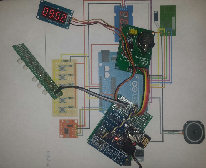
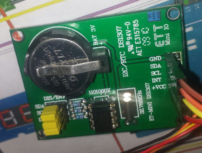
    I will need to make a bunch of modifications to the sketch. Mainly because I am using a different RTC module (DS1307). It is one that I have had laying around in my parts bin for years. I get a bunch of compile errors when I try to include the RTC library for this module.
    0_1509333483010_upload-75b8f66d-d692-412f-9171-d0175ea0402d

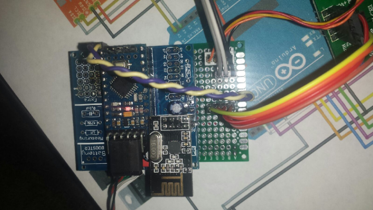
    Here is the board layout so far.
    0_1509333525901_upload-7777b1c8-2200-4300-aae8-c0a94786b7c8


  • @dbemowsk
    To use a 24 hour clock switch the following bool

    bool Screen_HourFormat24 = false;
    

    I think I used the colon to signify that an alarm was set, I think I flashed it on and off. in the Update_Screen method

       if ((Alarm1_Enabled) && (!Keys_ShowAlarmOnScreen)){
          if(Screen_ClockPoint)ledScreen.point(POINT_ON);
          else ledScreen.point(POINT_OFF);
        } else
          ledScreen.point(POINT_ON);


  • @micah said in 💬 Smart Alarm Clock:

    To use a 24 hour clock switch the following bool

    I wasn't necessarily saying that I wanted to switch to 24hr format. I was wondering if you had a way of indicating AM and PM when in 12 hour format.

    @micah said in 💬 Smart Alarm Clock:

    I think I used the colon to signify that an alarm was set, I think I flashed it on and off. in the Update_Screen method

    I see, so when it is blinking there is an alarm and when it is on solid there is not. I may add a different alarm indicator..

    One other question on this. I see you have 5 buttons on your switch panel. What were your planned uses of those 5 buttons? I didn't see anything documented on that.


  • The method Check_KeyPad (Line 300) handles the buttons.
    Currently my buttons do the following

    • show/program alarm
    • hour
    • minute
    • turn alarm on and off
    • turn on or off nightlight


  • Another thing that I've thought of is removing the RTC module completely since we can query the time from the server periodically.

    This would save components and pins, but it would limit the clock to only working with the controller, whereas the current design allows it to run independently


  • Plugin Developer

    😄 Wow, what an amazing design.


Suggested Topics

0
Online

11.2k
Users

11.1k
Topics

112.5k
Posts