Windows GUI/Controller for MySensors


  • Hero Member

    @tekka cool software! btw the sorting of the child sensors in the tree could be optimized.
    Right now the nodes are sorted like string instead of numbers:

    0 - ...
    1 - ...
    10 -
    11 -
    ...
    2 -
    21-
    ...


  • @tekka said:


    To update hit the update button or download here.


    Chrome blocks the download since it is "malicious".


  • Admin

    @samppa read my previous post::

    @AWI My guess is because of the upx-packed executable (MYSController.exe) in the archive being recognized as false positive.

    I didn't face a warning with IE or Firefox, but indeed, Chrome reports it.


  • Admin

    @Heinz thanks. I will add the number sorting in the next build.


  • Greetings Tekka,

    I am teaching myself programming while learning about the NRF24L01+ and various controllers and sensors. I have tried to download several free software controllers but yours is the only one that was straightforward enough for me to be successful. I have used it to monitor communication to and from my gateway but I am at a loss as to how to use your creation as a controller. It is the most wonderful tool for visualizing and debugging node-to-gateway communications because of the exceptional work you have done translating the command codes into real command words.

    Is there a way to input data through your GUI or is it best used as an output device? If input is accepted, would you be so kind as to elaborate on the subject enough to get me moving?

    Respectfully - Baran


  • Right click on a node and click Send Msg:

    upload-470b8000-35d1-49b5-8917-27fb9cf5934f


  • Thanks Eric - Way too cool!


  • Hi.
    I try your project ..and find problem in my side..
    I use MCU with USB - UART converter what possible set speed max 38kBps .. is possible in your MYSController set lower speed ??
    I thinks that you now use 115200 ..

    regards.


  • Contest Winner

    I'm looking some days into this topic, although I found not the time to test your very good looking software - The issue mentioned by dzairo would also be important for me. As I run my nodes at 8MHz I cannot use the default 115200kbps and use (also) 38kbps - so it would be important for me to change the BAUD rate too.

    Anyways - nice work!


  • ... some other problem is if you want run MCU in 3.3V then not possible use higher frequency .. then all use internal 8 Mhz RC oscillator and maximum speed is 38k ..
    this is reason why use 38k ..

    best regards.


  • Admin

    @Dirk_H , @dzairo: yup, will include this option in the next update. Thanks for reporting.


  • Thank you for this excellent work. I look forward to using it in my network. I just have a couple questions regarding setting up the GUI. I've read through this thread several times, but still have a couple of gaps in my understanding.

    1. Is the gateway that interfaces with the GUI an additional gateway which listens to, and sends node messages and updates? That is, additional to one that is interfaced with the controller (in my case a serial gateway connected to a Vera controller)?

    2. If my the answer to my first question is, yes, it is an additional gateway, is the code defining the operation different such that is does not interfere with the 'true' gateway? Or is the code the same (standard serial gateway sketch) but simply does not interfere?

    3. Do the nodes require the MYSBootloader in order to show up in the 'messages' tab, or will 'messages' tab show all node traffic regardless of bootloader? Of course for over the air (OTA) sketch updates it needs the MYSBootloader.

    4. Are these the correct steps to setup operation:

    a) download and extract the files.

    'b) place the bootloader folder into /arduino/hardware path such that the MYSBootloader and the associated boards show up in the 'tools->boards' menu.

    c) connect an Arduino with the gateway sketch to a computer using a USB cable (for the serial connection).

    d) run MYSController.exe (on windows) and select the COM port of the serial gateway in the configuration.

    e) hit connect and node traffic will show up in the 'messages' tab.

    If this is correct (and now that I write it down) it seems pretty straightforward, but I didn't see it explicitly described elsewhere. Sorry to be such a beginner, and thanks for straightening me out if I'm incorrect in any step.


  • Admin

    @therik said:

    Is the gateway that interfaces with the GUI an additional gateway which listens to, and sends node messages and updates? That is, additional to one that is interfaced with the controller (in my case a serial gateway connected to a Vera controller)?

    No, but certainly a good idea to look into.

    Do the nodes require the MYSBootloader in order to show up in the 'messages' tab, or will 'messages' tab show all node traffic regardless of bootloader? Of course for over the air (OTA) sketch updates it needs the MYSBootloader.

    No, the MYSBootloader is required for OTA updates with MYSController or compatible controllers.

    Are these the correct steps to setup operation:

    a) download and extract the files.

    'b) place the bootloader folder into /arduino/hardware path such that the MYSBootloader and the associated boards show up in the 'tools->boards' menu.

    c) connect an Arduino with the gateway sketch to a computer using a USB cable (for the serial connection).

    d) run MYSController.exe (on windows) and select the COM port of the serial gateway in the configuration.

    e) hit connect and node traffic will show up in the 'messages' tab.

    Yes, that's pretty much it. Copying the bootloader directory is only needed for updating to MYSBootloader via ISP.


  • Admin

    @Dirk_H , @dzairo BAUD option included in the latest release. Update via software or here.


  • @tekka Hello, I check your great software and do my first steps with mySensors.

    It looks very amazing!

    Here are my first comments:

    1. I must program the MYSBootloader with the H-fuse setting H:0xD8 (2048 word), the value H:0xDE (in your fuses.txt) or H:0xDA (in your boards.txt) didn't work for me.
    2. The blink.hex seems to be the normal blink sketch, it didn't have nrf24 functionality. Needs a local hardreset to flash other firmware.
    3. The Arduino IDE (with the enhanced boards.txt) isn't able to program a firmware with the MYSBootloader - think this results in the higher baud rate (115200 vs. 57600) and my case to have the Arduino running in a VM !?
    4. The update function in MYSController isn't working because it needs a proxy configuration (not imported).
    5. I got a warning sign on the nodes-tree, don't know what it mean, but node is working (no info in the context menu).
    6. The interrupt line of the ner24L01 isn't needed.
    7. A right click in the open context menu ( e.g. on clear firmware) forces a software error.
      8 ) After connecting the Serial GW the MYSController doesn't responce for a while (searching for nodes?) Maybe a background task or an indicater would be a idea ?!
      9)On XP (or XP style) a selected row in the mesages or nodes tab is not readable - the selection is in dark blue, the text in black.

    It should be possible to use the MYSBootloder (.hex) without changes also for 8Mhz nodes (internal RC L:0xE2), OTA only.
    The SPI is independent from the clock, Uart is not used, delays are 2 times longer but this should be no problem.

    Is there a scenario to keep your MYSController connected and have the mash working at the same time?
    For example, with a gateway connected at Raspberry PI and a TCP connection from MYSController to the RPI? Or with two gateways ?

    Looking forward for the next features :-),
    regards Pit


  • Admin

    @pit007 Thanks for your feedback.

    1. I must program the MYSBootloader with the H-fuse setting H:0xD8 (2048 word), the value H:0xDE (in your fuses.txt) or H:0xDA (in your boards.txt) didn't work for me.

    Ups, this is a mistake in the fuses.txt file, I will update that. The settings in the boards.txt are correct.
    The MYSBootloader 1.0 is 1834 bytes in size, therefore 0xDA works (1024W), but 0xD8 (2048W) is also ok (assuming you are programming the atmega328p). All calls are relative, and the MCU skips invalid commands (0xFF) until it starts parsing at 0x7800.

    1. The blink.hex seems to be the normal blink sketch, it didn't have nrf24 functionality. Needs a local hardreset to flash other firmware.

    yep, correct 🙂

    1. The Arduino IDE (with the enhanced boards.txt) isn't able to program a firmware with the MYSBootloader - think this results in the higher baud rate (115200 vs. 57600) and my case to have the Arduino running in a VM !?

    With MYSBootloader 1.0 you can only program a firmware with MYSController or similar tools. I'm currently working on a dual bootloader that includes OTA and Arduino IDE/AVRDude programming.

    1. The update function in MYSController isn't working because it needs a proxy configuration (not imported).

    Hmm, I assume you are referring to the check for updates function (automatically triggered after startup)? I will look into that.

    1. I got a warning sign on the nodes-tree, don't know what it mean, but node is working (no info in the context menu).

    The warning sign means no version/type information received. This information is sent during MYSBootloader startup, but not with conventional (e.g. optiboot) bootloaders.

    1. The interrupt line of the ner24L01 isn't needed.

    The communication is entirely controlled by the gateway - and yes, the interrupt pin is not used in the current gateway setup.

    1. A right click in the open context menu ( e.g. on clear firmware) forces a software error.

    Please send a screenshot to myscontroller@gmail.com

    8 ) After connecting the Serial GW the MYSController doesn't responce for a while (searching for nodes?) Maybe a background task or an indicater would be a idea ?!

    Please check the debug tab: any truncated messages or error flags after startup?

    1. On XP (or XP style) a selected row in the messages or nodes tab is not readable - the selection is in dark blue, the text in black.

    ok, will look into that.

    It should be possible to use the MYSBootloder (.hex) without changes also for 8Mhz nodes (internal RC L:0xE2), OTA only.
    The SPI is independent from the clock, Uart is not used, delays are 2 times longer but this should be no problem.

    Yes, 8Mhz should work, but ideally you recompile the bootloader with F_CPU set to 8 Mhz for correct delay timings.

    Is there a scenario to keep your MYSController connected and have the mash working at the same time?
    For example, with a gateway connected at Raspberry PI and a TCP connection from MYSController to the RPI? Or with two gateways ?

    Not yet, but I have some ideas...

    Have fun


  • Hi and thanks for a cool piece of software!

    I finally got around to soldering an ethernet gateway and decided to give this a spin. It worked like a charm for a while but now I get this error everytime any message goes through the gateway to Vera:

    myscontroller error.PNG

    OS is 32-bit Windows 7

    I can only get rid of this behaviour if I delete the configuration settings file and start over. It seems it only happens if I have logging enabled and exit the program and restart it.

    I'll have to start playing with the bootloader soon to get the OTA capabilities.


  • Hi.
    Just one idea .. your tools is very good .. why not add more better function ..
    1.If not received data from sensor more than predefined time then send email or tweet .. etc. for example using https://www.pushingbox.com/
    2. Make server version .. for web interface ..
    I thinks .. is possible order in TESCO cheap windows 8.1 tablet in price 90Euros ..
    one or two year later then will be possible buy in price around 50 euros .. why not use this platform?
    I use ASUS with USB serial port and work good .. if make easy uart to wifi (esp8266) converter then can work directly with wifi..


  • Admin

    @slarti I've seen this error if the log file is exclusively opened somewhere else. Try deleting or renaming the current logfile and restart the MYSController. I will change the log file handling in a upcoming release.


  • Admin

    @dzairo certainly an interesting idea! Please have a look at one of the discussed home automation solutions - there you can even define more complex scenarios.


  • yes.. I just that user use RPi etc hardware solution .. but in fact
    is possible buy tablet .. complete solution : standard windows 8.1 , LCD , battery .. wifi , bluetooth .. CE .. why not use this platform ..
    give link for - home automation solution..

    regards..

    PS: you can see , I my self make similar software for windows ..but more easy .. and why not use windows core for server , database .. etc ..


  • @tekka This GUI is great help especially for beginners like me who don't understand what the serial messages mean! You extract all the information so well and so beautifully.
    Hope its not too much to ask, but may I take a look at the source code? Because I need to know the method you used to extract the messages, as well as tying the data to the proper fields. I somehow need to push all of these data to the proper fields in my database and I'm stuck at deciphering the messages being received. Thanks in advance and cheers!


  • Contest Winner

    This is a nice tool. Good work! Is there any possibility to get support for all the message types on the development branch as well?


  • Admin

    @Anticimex Thanks 🙂 Yes, I in the upcoming release.


  • Hi.
    One idea .. FIFO buffer for outgoing message..
    low power relay node .. if use bi stable relay then is possible to power only from battery .. but radio must go to sleep.. then wake up every 5 or 10 second .. and ask gateway for new command ..
    node just if wake up then waiting for example 0,5 sec for incoming message .. if not received then go sleep ..
    gateway wait for node .. and if got command in FIFO for this node then send message ..
    just idea..


  • Admin

    @dzairo excellent idea, this will be implemented in the .276 release. Thanks


  • Hi.
    ...ehm , in Windows is possible use database and install web server .. you have idea use this?
    database is good way , pls try thinking about my idea using cheap windows tablet as controller , by serial port (usb) or lan (wifi ..etc) . .. problem is that tablet memory is not good for many write cycle .. but this is possible solve ..
    best regards


  • Hi Tekka,
    Great tool and SO useful for debugging.
    I have MYSController running under Wine on Linux Mint with no problems.

    I do have one small issue though. I have a serial gateway that reports to Domoticz on my Mint PC. This works fine and MSController connects fine. When I tried to move my gateway to a remote installation of Domoticz on a Raspberry Pi (same network) MSController cannot see it if I try to connect by TCP. I hope it's just something silly like port no. or something, but any ideas?

    Many thanks


  • Admin

    @blackdog65 You will have to pipe the serial gateway via tcp:port with e.g. ser2net.


  • @tekka WOW! I thought that was going to be SO difficult... but it took 10mins total! Thank you very much... I'm good to go 😉


  • Admin

    For completeness, here are the MYSBootloader instructions for OTA updates via MYSController:

    1. Load gw sketch and connect arduino either via serial or ethernet port. No special bootloader needed for that part (i.e. standard optiboot bootloader will do the job).

    2. Add these lines to the boards.txt file in your Arduino IDE installation folder (located somewhere like C:/Program Files/Arduino/hardware/arduino/avr)

      proMYSBL16.name=ATmega328 external 16Mhz with MYSBootloader
      proMYSBL16.upload.tool=avrdude
      proMYSBL16.upload.protocol=arduino
      proMYSBL16.upload.maximum_size=30720
      proMYSBL16.upload.maximum_data_size=2048
      proMYSBL16.upload.speed=115200
      proMYSBL16.bootloader.tool=avrdude
      proMYSBL16.bootloader.low_fuses=0xF7
      proMYSBL16.bootloader.high_fuses=0xDA
      proMYSBL16.bootloader.extended_fuses=0x06
      proMYSBL16.bootloader.unlock_bits=0x3F
      proMYSBL16.bootloader.lock_bits=0x3F
      proMYSBL16.bootloader.file=MySensors/MYSBootloader.hex
      proMYSBL16.build.mcu=atmega328p
      proMYSBL16.build.f_cpu=16000000L
      proMYSBL16.build.board=AVR_UNO
      proMYSBL16.build.core=arduino
      proMYSBL16.build.variant=standard

      ######## settings for 8Mhz internal clock

      proMYSBL8.name=ATmega328 internal 8Mhz with MYSBootloader
      proMYSBL8.upload.tool=avrdude
      proMYSBL8.upload.protocol=arduino
      proMYSBL8.upload.maximum_size=30720
      proMYSBL8.upload.maximum_data_size=2048
      proMYSBL8.upload.speed=57600
      proMYSBL8.bootloader.tool=avrdude
      proMYSBL8.bootloader.low_fuses=0xE2
      proMYSBL8.bootloader.high_fuses=0xDA
      proMYSBL8.bootloader.extended_fuses=0x06
      proMYSBL8.bootloader.unlock_bits=0x3F
      proMYSBL8.bootloader.lock_bits=0x3F
      proMYSBL8.bootloader.file=MySensors/MYSBootloader.hex
      proMYSBL8.build.mcu=atmega328p
      proMYSBL8.build.f_cpu=8000000L
      proMYSBL8.build.board=AVR_UNO
      proMYSBL8.build.core=arduino
      proMYSBL8.build.variant=standard

    3. Copy MYSBootloader.hex (from MYSController/Bootloader folder) to the Arduino IDE installation folder C:/Program Files/Arduino/hardware/arduino/avr/bootloaders/MySensors/

    4. Restart Arduino IDE, choose under Tools | Board | ATmega328 external 16Mhz with MYSBootloader or Tools | Board | ATmega328 internal 8Mhz with MYSBootloader depending on your HW settings

    5. Connect USBasp to sensor node and select Tools | Burn Bootloader

    6. If everything worked well until here, you now have the MYSBootloader with the fuse settings from above burnt to your sensor node (16Mhz extXTAL or 8Mhz intRC, BOOTSZ 1024W, BOD 1V8).

    7. Please use the AVR fuse calculator to retrieve the individual fuse settings. If you need to change frequency, BOD or other settings, change the fuse settings based on the fuse calculator.
      Important: The MYSBootloader.hex file was compiled for 16Mhz oscillators but it should also work at 8Mhz. If you intend to go below 8Mhz, I highly recommend to compile the bootloader with adjusted frequency settings.

    8. Start MYSController, hit config and adjust settings (COM-Port & baud or IP address:port)

    9. Hit connect: Connection to gateway should be established (gateway answers with gateway ready message), the node should appear and request an ID & FW.

    10. Right-mouse click on that node, select assign FW, choose for example **TimeReporter ** (demo firmware included in the MYSController/Firmware folder). Then click reboot and wait until FW is uploaded and node boots.

    11. TimeReporter firmware reports every few seconds some values such as time, millis, and voltage.

    12. Custom firmware: compile your sketch and retrieve the generated .hex file (activate verbose mode in the Arduino IDE to get compiler messages and output path).

    13. Copy .hex file to MYSController/Firmware folder and edit firmware_config.csv file according to the existing lines.

    14. Hit Refresh Repo in MYSController and the newly copied firmware should appear in the Assign FW dropdown list, ready to be uploaded.

    Have fun 🙂


  • ..nice..
    .. and you try add new function what we talking above..? .. if make node with bi-stable relay battery powered only ..

    regards..


  • Contest Winner

    Hi,
    I have tried to use the GUI controller but I cannot get any output although it claims to be connected to my ethernet GW.
    I should mention that I run on the development branch. Perhaps there are changes that prevents your tool from acknowlegding my "development" gateway?
    EDIT: When connected through serial, it seem to work though. Perhaps the gw does not permit multiple connections on Ethernet. Nice! It barfs on my messages though but I guess it is because I run on dev and you have already stated that development branch support is "coming" so I don't worry about that.
    This is the output though in case you are interested:

    2015-03-10 20:31:02 ERROR: Truncated message, Msg=101;1;1;1;36;0
    101;1;1;1;36;0
    2015-03-10 20:31:14 RECV: 101;1;1;1;36;1
    101;1;1;1;36;1
    2015-03-10 20:31:14 ERROR: Truncated message, Msg=101;1;1;1;36;1
    101;1;1;1;36;1
    2015-03-10 20:31:20 RECV: 101;1;1;1;36;0
    101;1;1;1;36;0
    2015-03-10 20:31:20 ERROR: Truncated message, Msg=101;1;1;1;36;0
    101;1;1;1;36;0

  • Admin

    MYSController 0.1.2.276 and MYSBootloader 1.1 released:

    • send message upon RX (for battery-powered nodes)
    • bootloader commands (for MYSBootloader 1.1)
    • bugfixes

    Enjoy!


  • @tekka
    Thanks!
    Where can this be downloaded? Is that under an open source license, are sources available in github or something? If so, maybe someone would be willing to help with making it platform independent 🙂


  • @tekka very good job 👍 Thx !

    The ID change worked (but tried it only one time 🙂 A stesstest will follow ! )

    Next thing: Know how often a node send a package (or how long it like to sleep) and take this info to create a quality level and a warning if - i.e. after 3 times - there is no feedback from the node ?

    • Pit


  • The included TimeReporter (I don't know where to find the sketch) has a small problem.
    In the minutes and the seconds the leading zero is missing - i.e. 11h 9 min 5 sevc is shown as: 11:9:5 instead of 11:09:05.

    -Pit


  • i tried using the OTA FW update by following your guide a few posts up and i must say i like it a lot!
    i just cant figure out how to upload FW from the software. every time it starts uploading FW by responding on FW requests my gateway seems to freeze, i use a usb ttl converter and arduino pro mini with radio as gw. i also uploaded the log. by the time the server responds to the FW req i have assigned FW to the node. then the GW just stops recieving and transmitting for no apearent reason so there is no communication back and forth, then when i reset the GW ( by pushing the reset button on the GW the comm is back up.. when the GW is frosen the led (pin 13, clock) is also completely off.. and yes, i also tried a radio with capacitor.
    MySensors_20150318-202006.log


  • Admin

    @diamantmatch The link to the log file is broken (currently, the forum experiences some issues with uploading files / pictures. Can you share it on e.g. dropbox and post the link?).
    I've come across similar issues with debug mode activated on the GW sketch - try reflashing the GW with debug mode disabled and give it another shot.


  • Admin

    @tekka said:

    the forum experiences some issues with uploading files

    @diamantmatch
    I have cherry-picked a couple of patches that should fix file-uploads now. Please try to re-upload your log file. Downloading your logfile works again.


  • @tekka
    Awesome! everything now works like a charm! many thanks for your help!


  • @tekka I am still a bit confused after rereading this thread.

    I have a humidity sensor plugged by usb and using config and debug see this sensor.
    Question is for the full gui do I need to unplug serial usb from gw and plug it into computer and start your program?

    If this is correct, then it will be temporarily disconnected from vera3 controller while I study and learn to understand what is being presented to me, when I again config and debug.

    After reviewing then reconfigure gw back to vera?


  • @tekka I update my bootloader to MYSbootloader and the fuses as per the doc but now when I try to program the Arduino mini pro I get this error can you help?

    upload-42f4e020-3b06-4acb-90b2-87beaeebdcac


  • Admin

    @5546dug MYSController connects directly to the gw to interact with the nodes.


  • Admin

    @Francois said:

    @tekka I update my bootloader to MYSbootloader and the fuses as per the doc but now when I try to program the Arduino mini pro I get this error can you help?

    upload-42f4e020-3b06-4acb-90b2-87beaeebdcac

    That's correct: with the MYSBootloader you can upload the firmware OTA only - use MYSController to upload new fw


  • thank you @tekka , will try it.


  • @tekka A further small bug or misunerstanding by us - the unix time:

    API:
    I_TIME 1 Sensors can request the current time from the Controller using this message. The time will be reported as the seconds since 1970 = unix time ?

    The MYSController send the local time, but not the unix time (the unix time is the same all over te world)


  • @tekka what does the dc =1 mean in this example?
    I understand the s c t pt and l but not d
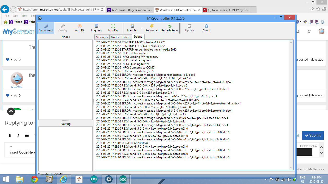
Screenshot (40).png c

    is the humidity sensor ok?
    pro mini
    serial gw nano to win 8.1 via usb interface
    ver 1.4
    lib 1.4
    humidity sketch mysensors

    readings seem accurate

    also have temp read 30 sec and hum read when changes only

    is all well or issues?

    thanks


  • Admin

    @5546dug dc=1 indicates that the message is truncated (i.e. you lack the first part of the telegram, see below). Please make sure, that you are running the most recent version of the library, i.e. 1.4.1.

    Your messages lack the bytes in bold:

    3/25/2015 23:24:29 RECV: **5;0;1;0;1;**send: 5-5-0-0...etc


  • You seem to have a sensor connected to your MYSController and not a gateway.
    Maybe wrong serialport?

    /J


  • Admin

    "
    @JeJ indeed, you are right. thanks!


  • Hi guys! I'm still a newbie but i'm very interested in this tool and I'm quite confused how to install it. I'm only interested in see the communication to start with.

    Is there an installation instruction somewhere?

    I have tried to install it but I can't see any serial ports in the config window. Here is what I have done:

    1. Downloaded the package and run the program (I'm using Wine on a Mac)
    2. Uploaded a the standard SerialGateway sketch from Mysensor to a Nano board and have it connected to the computer. I can see from the serial monitor in the Arduino IDE that it sees the communication fine from the various sensors.
      I haven't done anything to the Gateway that's connected to the Vera. Is it that one I should use and connect to the computer???

    Sorry for the newbie questions..


  • Well I found an old Windows laptop and it worked on that, so I guess it's the Mac computer 😥
    Yesterday I tried to make a Repeater with the standard sketch as instructed. Now I can see that it says: Undefined firmware/type. What is the reason for that???

    30-03-2015 15:03:38 NODE: New node discovered, node id=34
    30-03-2015 15:03:38 CHILD: New child discovered, node id=34, child id=internal
    30-03-2015 15:03:38 DEBUG: Update child id=255, type=ARDUINO_RELAY
    30-03-2015 15:03:38 RECV: 0;0;3;0;9;read: 34-34-0 s=255,c=3,t=6,pt=1,l=1:0
    30-03-2015 15:03:38 RECV: 34;255;3;0;6;0
    30-03-2015 15:03:38 SEND: 34;255;3;0;6;M
    30-03-2015 15:03:38 RECV: 0;0;3;0;9;send: 0-0-34-34 s=255,c=3,t=6,pt=0,l=1,st=ok:M
    30-03-2015 15:03:40 RECV: 0;0;3;0;9;read: 34-34-0 s=255,c=3,t=11,pt=0,l=13:Repeater Node
    30-03-2015 15:03:40 RECV: 34;255;3;0;11;Repeater Node
    30-03-2015 15:03:40 DEBUG: Undefined firmware/type for node=34
    30-03-2015 15:03:40 RECV: 0;0;3;0;9;read: 34-34-0 s=255,c=3,t=12,pt=0,l=3:1.0
    30-03-2015 15:03:40 RECV: 34;255;3;0;12;1.0
    30-03-2015 15:03:40 DEBUG: Undefined firmware/type for node=34

    I think it works because when I disconnect it stops sending messages to MYSController so all communication to this is done via the repeater.
    Is it something to worry about???


  • Admin

    @Mouridsen MYSController should work using Wine on Mac - for the serial communication, just type e.g. /dev/ttyUSB0 or whatever your GW is assigned to in the serial edit field. The "undefined firmware/type" message appears, if you use the standard arduino bootloader (e.g. optiboot). For OTA functionality, you can use MYSBootloader which will also transmit the firmware type/version to MYSController.


  • @tekka Thanks, it works perfect. That was a quite easy fix 🙂


  • Admin

    MYSController Version 0.1.2.278 released

    New features:

    • Support MYSBootloader 2.0 / SHA (signing bootloader) ==> will be released in the nearest future
    • Support 1.5 framework (dev branch)
    • Parse MySensors log/debug messages
    • Div. options

    Changelog:

    • Moved send message dialog to main window
    • Handler adjustments
    • Bugfix FW upload in GW debug mode
    • Bugfix message logging

    Update via update button in MYSController or download here.


  • Brilliant work! Ran perfectly under Wine on Fedora linux by using /dev/ttyUSB0 for serial port [after first checking my gateway was connected to that port]. Solved a problem I was having with a sensor getting assigned a weird node ID. Saved me loads of time tracking down the problem, many thanks for sharing this tool, much appreciated!


  • This is awesome!

    Any plans to provide source or a back-end API that could be used to connect this up to an HA controller? That way you could control everything downstream in the MySensors cloud from this app, and everything upstream (the HA controller and the cloud) could interface with a much richer (and presumably more robust) infrastructure rather than yet again figuring out how to parse the bits coming off of the serial port...


  • @rickmontana83 parse the data from the serial port is easy, im put in other post in this forum with a part of my code in vb.net


  • Admin

    @rickmontana83 Serial API is described here.


  • @tekka once you flash the Arduino with the MYSBootloader is the only why that now you can programme the Arduino is though the MYSController software?


  • Admin

    @Francois AFAIK, MYSController and NodeJsController (see framework, link here) are the only controllers that provide OTA updates via bootloader. Both controllers use the OTA protocol described here. However, MYSBootloader 2.0 will support updates OTA and via IDE.


  • @tekka the reason I asked I has a problem where I had 2 node with the same node ID and a could not do a OTA via MYSController. As i keep the same ID. I clear the EEPROM and still l it did not work. So the only why I could get the node working was to reflash the boot loader.


  • Admin

    @Francois in general, if two nodes have the same ID, you have to disconnect one node and reassign ID/clear eeprom of the other node:

    • MYSBootloader 1.1: use the bootloader commands in MYSController (right mouse click on the node, then reassign ID or clear EEPROM)
    • MYSBootloader 1.0: upload the clear eeprom sketch and have the controller reassigning the ID


  • @tekka I doing this and still the node ID is not changing. I change this node to 4 and it still come up as Node 3. The reboot command also don't reboot the device. I have to do a manual reset on the device is this normal?

    upload-fcaad57f-daaa-4259-8905-9c148719e332


  • Admin

    @Francois ok, I see - can you post or send the log (with debug mode on) to myscontroller at gmail dot com.
    If the reboot command is not functioning properly you may have a corrupt routing table: Try clearing the routing table of the node & all routing nodes in between (right mouse click on the node in the routing panel|clear routing table) then try again to reboot.


  • @tekka will it be a problem if I don't have all my node on the MYSbootloader? Currently I only have 2 of my nodes with MYSBootloader. I am still testing before I change all the nodes


  • Admin

    @Francois should be fine


  • @tekka log file send


  • @tekka See below it reboot the first time when I try it the seconde time it did
    not it just say reboot

    upload-c74f717f-972d-42a4-8346-7dac5fd0bc3a

    Here is my routing Tabel:

    upload-eab02958-9c75-4343-b325-7578209d761f


  • Admin

    @Francois the node has AUTO ID or fix assigned ID (i.e. 91?) - if so, this may be an issue in the dev branch


  • Hero Member

    Anyone who owns a Vera controller, and perhaps was able to connect this nice MYSController to the mySensors serial-gateway hooked into Vera USB?

    The serial port is exposed in TCP/IP by Vera via ser2net, however I wasn't successful by setting MYSController to <my-vera-ip>:3482 (3482 is the port displayed in Vera -> APPS -> Develop Apps -> Serial port config ) .

    (maybe the Vera MYSensor plugin opens the serial connection to GW in 'exclusive' mode or something like that? )

    If I remove the GW from Vera USB and plug in my computer, MYSController works fine.

    Anyone? Am I wanting too much?


  • I'm new to MySensors and playing around with this implementation since some weeks. I implemented an interface from serial to MQTT per python and everything is running fine so far. The last days I spend some time with the bootloader (it is a great feature!!!). I created also a python mqtt client that will take care on that.

    I got really crazy the last 2 days with the CRC calculation. I always got a different CRC as as the MYSController. Now I found out, that it seems that the last byte within the HEX file is interpreted as 0xFF instead of the real data. I flashed now one sensor with the MYSController and as I can see in the log-file -> the last byte is read from the HEX as wrong value (0xFF instead of 0x14) -> therefore the HEX file is not flashed correctly (last byte is wrong) -> it seems that this is a bug in MYSController. (I'm using version 0.1.2.278)

    Can you check that please?


  • Admin

    @JoergP Indeed, bug confirmed. There is an error in the block padding code. I will push the update soon. Thanks for reporting!


  • Hello,

    First of all, thanks Tekka for the great MYScontroller!

    I want to get started with the MYSbootloader but I can't get it to work. I've followed each step securely but I never "see" my arduino in MYScontroller after flashing the bootloader. Perhaps I misunderstand the theory behind the bootloader? Maybe the fuses are wrong, I don't know.

    Perhaps someone can reply to the following;

    • Can I just attach a radio module to an Arduino Nano as instructed on the site, clear the eeprom and then burn the bootloader using usbasp? (as instructed in this thread) Or do I need to upload the gateway sketch before burning the bootloader?
    • I have a hard time understanding what the bootloader does, I think it enables low level nrf functionality for OTA and Myscontroller instructions like reboot and clear eeprom etc. But when I upload a sketch does that mean the bootloader inits the nrf first and then the uploaded sketch will just re-init the nrf again?
    • Is there a way to debug the bootloader?

    Have a good laugh if you will at these noob questions, but any help is appreciated 🙂


  • Admin

    @cdr said:

    • Can I just attach a radio module to an Arduino Nano as instructed on the site, clear the eeprom and then burn the bootloader using usbasp? (as instructed in this thread) Or do I need to upload the gateway sketch before burning the bootloader?

    Yes, simply attach the radio and burn the bootloader with the correct fuse settings (see the fuses.txt file in the bootloader directory). If you intend to use MYSController, set AutoID to automatically assign IDs to the nodes.

    • I have a hard time understanding what the bootloader does, I think it enables low level nrf functionality for OTA and Myscontroller instructions like reboot and clear eeprom etc. But when I upload a sketch does that mean the bootloader inits the nrf first and then the uploaded sketch will just re-init the nrf again?

    Yes, that's correct. The bootloader is a small piece of code located at the end of the flash area that is (if the fuses are set accordingly) executed first upon rebooting and allows for low-level OTA updates.

    • Is there a way to debug the bootloader?

    Yes, there are several ways (e.g. visual with LED, serial output, or AVR DebugWire)...you may want to google these topics for further information..

    Have a good laugh if you will at these noob questions, but any help is appreciated 🙂

    no problem 🙂


  • Hi tekka,

    Thanks for the response and clarification. I think I need more knowledge about fuses and bootloaders, it could be that the arduino clones are giving me sh&t.

    Looking forward to my success and MYSloader 2.0 ofcourse!

    Thanks again for all your work.


  • Admin

    MYSController Version 0.1.2.280 released

    Changelog:

    • Bugfix FW padding (thanks @JoergP)
    • Handler rework
    • Logging format rework
    • Support battery-powered/sleeping nodes
    • Refactoring

    Update via update button in MYSController or download here.


  • This is the most helpful tool I used since I started messing around with mysensors.

    I hate to nag but this tool source code would be a giant step to someone looking to create a new controller by himself.
    .


  • Hello, how to verify right bootloader is uploaded to arduino?

    I'm using two Arduino Pro Mini 328 5.0V 16Mhz, one as ArduinoISP programmer and one as sensor node to upload bootloader and firmware.

    I followed manual (http://forum.mysensors.org/topic/838/windows-gui-controller-for-mysensors/76) step by step.

    I have tried MYSBootloader.hex coming from latest MYSController 0.1.2.280 and MYSBootloader.hex (1.1) from github with same results.

    Upload log is here:

    C:\Program Files (x86)\Arduino\hardware\tools\avr/bin/avrdude -CC:\Program Files (x86)\Arduino\hardware\tools\avr/etc/avrdude.conf -v -patmega328p -cstk500v1 -PCOM10 -b19200 -e -Ulock:w:0x3F:m -Uefuse:w:0x06:m -Uhfuse:w:0xDA:m -Ulfuse:w:0xF7:m 
    
    avrdude: Version 6.0.1, compiled on Apr 15 2015 at 19:59:58
             Copyright (c) 2000-2005 Brian Dean, http://www.bdmicro.com/
             Copyright (c) 2007-2009 Joerg Wunsch
    
             System wide configuration file is "C:\Program Files (x86)\Arduino\hardware\tools\avr/etc/avrdude.conf"
    
             Using Port                    : COM10
             Using Programmer              : stk500v1
             Overriding Baud Rate          : 19200
             AVR Part                      : ATmega328P
             Chip Erase delay              : 9000 us
             PAGEL                         : PD7
             BS2                           : PC2
             RESET disposition             : dedicated
             RETRY pulse                   : SCK
             serial program mode           : yes
             parallel program mode         : yes
             Timeout                       : 200
             StabDelay                     : 100
             CmdexeDelay                   : 25
             SyncLoops                     : 32
             ByteDelay                     : 0
             PollIndex                     : 3
             PollValue                     : 0x53
             Memory Detail                 :
    
                                      Block Poll               Page                       Polled
               Memory Type Mode Delay Size  Indx Paged  Size   Size #Pages MinW  MaxW   ReadBack
               ----------- ---- ----- ----- ---- ------ ------ ---- ------ ----- ----- ---------
               eeprom        65    20     4    0 no       1024    4      0  3600  3600 0xff 0xff
               flash         65     6   128    0 yes     32768  128    256  4500  4500 0xff 0xff
               lfuse          0     0     0    0 no          1    0      0  4500  4500 0x00 0x00
               hfuse          0     0     0    0 no          1    0      0  4500  4500 0x00 0x00
               efuse          0     0     0    0 no          1    0      0  4500  4500 0x00 0x00
               lock           0     0     0    0 no          1    0      0  4500  4500 0x00 0x00
               calibration    0     0     0    0 no          1    0      0     0     0 0x00 0x00
               signature      0     0     0    0 no          3    0      0     0     0 0x00 0x00
    
             Programmer Type : STK500
             Description     : Atmel STK500 Version 1.x firmware
             Hardware Version: 2
             Firmware Version: 1.18
             Topcard         : Unknown
             Vtarget         : 0.0 V
             Varef           : 0.0 V
             Oscillator      : Off
             SCK period      : 0.1 us
    
    avrdude: AVR device initialized and ready to accept instructions
    
    Reading | ################################################## | 100% 0.05s
    
    avrdude: Device signature = 0x1e950f
    avrdude: erasing chip
    avrdude: reading input file "0x3F"
    avrdude: writing lock (1 bytes):
    
    Writing | ################################################## | 100% 0.03s
    
    avrdude: 1 bytes of lock written
    avrdude: verifying lock memory against 0x3F:
    avrdude: load data lock data from input file 0x3F:
    avrdude: input file 0x3F contains 1 bytes
    avrdude: reading on-chip lock data:
    
    Reading | ################################################## | 100% 0.02s
    
    avrdude: verifying ...
    avrdude: 1 bytes of lock verified
    avrdude: reading input file "0x06"
    avrdude: writing efuse (1 bytes):
    
    Writing | ################################################## | 100% 0.02s
    
    avrdude: 1 bytes of efuse written
    avrdude: verifying efuse memory against 0x06:
    avrdude: load data efuse data from input file 0x06:
    avrdude: input file 0x06 contains 1 bytes
    avrdude: reading on-chip efuse data:
    
    Reading | ################################################## | 100% 0.01s
    
    avrdude: verifying ...
    avrdude: 1 bytes of efuse verified
    avrdude: reading input file "0xDA"
    avrdude: writing hfuse (1 bytes):
    
    Writing | ################################################## | 100% 0.03s
    
    avrdude: 1 bytes of hfuse written
    avrdude: verifying hfuse memory against 0xDA:
    avrdude: load data hfuse data from input file 0xDA:
    avrdude: input file 0xDA contains 1 bytes
    avrdude: reading on-chip hfuse data:
    
    Reading | ################################################## | 100% 0.02s
    
    avrdude: verifying ...
    avrdude: 1 bytes of hfuse verified
    avrdude: reading input file "0xF7"
    avrdude: writing lfuse (1 bytes):
    
    C:\Program Files (x86)\Arduino\hardware\tools\avr/bin/avrdude -CC:\Program Files (x86)\Arduino\hardware\tools\avr/etc/avrdude.conf -v -patmega328p -cstk500v1 -PCOM10 -b19200 -Uflash:w:C:\Program Files (x86)\Arduino\hardware\arduino\avr/bootloaders/MySensors/MYSBootloader.hex:i -Ulock:w:0x0F:m 
    
    avrdude: Version 6.0.1, compiled on Apr 15 2015 at 19:59:58
             Copyright (c) 2000-2005 Brian Dean, http://www.bdmicro.com/
             Copyright (c) 2007-2009 Joerg Writing | ################################################## | 100% 0.02s
    
    avrdude: 1 bytes of lfuse written
    avrdude: verifying lfuse memory against 0xF7:
    avrdude: load data lfuse data from input file 0xF7:
    avrdude: input file 0xF7 contains 1 bytes
    avrdude: reading on-chip lfuse data:
    
    Reading | ################################################## | 100% 0.02s
    
    avrdude: verifying ...
    avrdude: 1 bytes of lfuse verified
    
    avrdude done.  Thank you.
    
    Wunsch
    
             System wide configuration file is "C:\Program Files (x86)\Arduino\hardware\tools\avr/etc/avrdude.conf"
    
             Using Port                    : COM10
             Using Programmer              : stk500v1
             Overriding Baud Rate          : 19200
             AVR Part                      : ATmega328P
             Chip Erase delay              : 9000 us
             PAGEL                         : PD7
             BS2                           : PC2
             RESET disposition             : dedicated
             RETRY pulse                   : SCK
             serial program mode           : yes
             parallel program mode         : yes
             Timeout                       : 200
             StabDelay                     : 100
             CmdexeDelay                   : 25
             SyncLoops                     : 32
             ByteDelay                     : 0
             PollIndex                     : 3
             PollValue                     : 0x53
             Memory Detail                 :
    
                                      Block Poll               Page                       Polled
               Memory Type Mode Delay Size  Indx Paged  Size   Size #Pages MinW  MaxW   ReadBack
               ----------- ---- ----- ----- ---- ------ ------ ---- ------ ----- ----- ---------
               eeprom        65    20     4    0 no       1024    4      0  3600  3600 0xff 0xff
               flash         65     6   128    0 yes     32768  128    256  4500  4500 0xff 0xff
               lfuse          0     0     0    0 no          1    0      0  4500  4500 0x00 0x00
               hfuse          0     0     0    0 no          1    0      0  4500  4500 0x00 0x00
               efuse          0     0     0    0 no          1    0      0  4500  4500 0x00 0x00
               lock           0     0     0    0 no          1    0      0  4500  4500 0x00 0x00
               calibration    0     0     0    0 no          1    0      0     0     0 0x00 0x00
               signature      0     0     0    0 no          3    0      0     0     0 0x00 0x00
    
             Programmer Type : STK500
             Description     : Atmel STK500 Version 1.x firmware
             Hardware Version: 2
             Firmware Version: 1.18
             Topcard         : Unknown
             Vtarget         : 0.0 V
             Varef           : 0.0 V
             Oscillator      : Off
             SCK period      : 0.1 us
    
    avrdude: AVR device initialized and ready to accept instructions
    
    Reading | ################################################## | 100% 0.06s
    
    avrdude: Device signature = 0x1e950f
    avrdude: NOTE: "flash" memory has been specified, an erase cycle will be performed
             To disable this feature, specify the -D option.
    avrdude: erasing chip
    avrdude: reading input file "C:\Program Files (x86)\Arduino\hardware\arduino\avr/bootloaders/MySensors/MYSBootloader.hex"
    avrdude: writing flash (32722 bytes):
    
    Writing | ################################################## | 100% -0.00s
    
    avrdude: 32722 bytes of flash written
    avrdude: verifying flash memory against C:\Program Files (x86)\Arduino\hardware\arduino\avr/bootloaders/MySensors/MYSBootloader.hex:
    avrdude: load data flash data from input file C:\Program Files (x86)\Arduino\hardware\arduino\avr/bootloaders/MySensors/MYSBootloader.hex:
    avrdude: input file C:\Program Files (x86)\Arduino\hardware\arduino\avr/bootloaders/MySensors/MYSBootloader.hex contains 32722 bytes
    avrdude: reading on-chip flash data:
    
    Reading | ################################################## | 100% 0.02s
    
    avrdude: verifying ...
    avrdude: 32722 bytes of flash verified
    avrdude: reading input file "0x0F"
    avrdude: writing lock (1 bytes):
    
    Writing | ################################################## | 100% 0.05s
    
    avrdude: 1 bytes of lock written
    avrdude: verifying lock memory against 0x0F:
    avrdude: load data lock data from input file 0x0F:
    avrdude: input file 0x0F contains 1 bytes
    avrdude: reading on-chip lock data:
    
    Reading | ################################################## | 100% 0.01s
    
    avrdude: verifying ...
    avrdude: 1 bytes of lock verified
    
    avrdude done.  Thank you.


    Fuses looks like right:

    avrdude: Device signature = 0x1e950f
    avrdude: safemode: lfuse reads as F7
    avrdude: safemode: hfuse reads as DA
    avrdude: safemode: efuse reads as 6
    

    MYSController log after node with new bootloader start:

    14.06.2015 10:14:46	STARTUP	Initialize message logging
    14.06.2015 10:14:46	STARTUP	MYSController 0.1.2.280
    14.06.2015 10:14:46	STARTUP	FPC 2.6.4 / Lazarus 1.4
    14.06.2015 10:14:46	STARTUP	still under development :) tekka 2015
    14.06.2015 10:14:46	STARTUP	Load INI file...
    14.06.2015 10:14:46	STARTUP	INI version 0.1.2.280
    14.06.2015 10:14:46	INFO	*** Logging START ***
    14.06.2015 10:14:46	VERSION	MYSController 0.1.2.280
    14.06.2015 10:14:46	STARTUP	INI file loaded
    14.06.2015 10:14:46	STARTUP	Loading FW repository...
    14.06.2015 10:14:46	REPO	FW "Blink" loaded. t=10, v=1, blocks=72, crc=0xD098
    14.06.2015 10:14:46	REPO	FW "TimeReporter" loaded. t=20, v=1, blocks=840, crc=0x4AC5
    14.06.2015 10:14:46	REPO	FW repository loaded. Items=2
    14.06.2015 10:14:46	STARTUP	Initialize message types
    14.06.2015 10:14:46	NODE	New node discovered, node id=0
    14.06.2015 10:14:46	NODE	New node discovered, node id=255
    14.06.2015 10:14:49	INFO	Connected to 192.168.0.1:12345
    14.06.2015 10:14:59	UPDATE	4295098648
    14.06.2015 10:21:26	CHILD	New child discovered, node id=0, child id=0
    14.06.2015 10:21:26	RX	0;0;3;0;9;read: 255-255-255 s=255,c=3,t=7,pt=0,l=0,sg=0:
    14.06.2015 10:21:26	RX	0;0;3;0;9;send: 0-0-255-255 s=255,c=3,t=8,pt=1,l=1,sg=0,st=bc:0
    14.06.2015 10:21:28	RX	0;0;3;0;9;read: 3-3-255 s=255,c=3,t=7,pt=0,l=0,sg=0:
    14.06.2015 10:21:28	RX	0;0;3;0;9;send: 0-0-3-3 s=255,c=3,t=8,pt=1,l=1,sg=0,st=ok:0
    14.06.2015 10:21:30	RX	0;0;3;0;9;read: 3-3-0 s=255,c=3,t=6,pt=1,l=1,sg=0:0
    14.06.2015 10:21:30	NODE	New node discovered, node id=3
    14.06.2015 10:21:30	CHILD	New child discovered, node id=3, child id=internal
    14.06.2015 10:21:30	TX	3;255;3;0;6;M
    14.06.2015 10:21:30	RX	3;255;3;0;6;0
    14.06.2015 10:21:30	RX	0;0;3;0;9;send: 0-0-3-3 s=255,c=3,t=6,pt=0,l=1,sg=0,st=ok:M
    14.06.2015 10:21:32	RX	0;0;3;0;9;read: 3-3-0 s=255,c=3,t=11,pt=0,l=7,sg=0:Balcony
    14.06.2015 10:21:32	RX	3;255;3;0;11;Balcony
    14.06.2015 10:21:32	RX	0;0;3;0;9;read: 3-3-0 s=255,c=3,t=12,pt=0,l=3,sg=0:1.0
    14.06.2015 10:21:32	RX	3;255;3;0;12;1.0
    14.06.2015 10:21:32	RX	0;0;3;0;9;read: 3-3-0 s=1,c=0,t=16,pt=0,l=20,sg=0:Photoconductive Cel
    14.06.2015 10:21:32	CHILD	New child discovered, node id=3, child id=1
    14.06.2015 10:21:32	DEBUG	Update child id=1, type=LIGHT_LEVEL
    14.06.2015 10:21:32	RX	3;1;0;0;16;Photoconductive Cell
    14.06.2015 10:21:32	RX	0;0;3;0;9;read: 3-3-0 s=2,c=0,t=6,pt=0,l=3,sg=0:ds0
    14.06.2015 10:21:32	CHILD	New child discovered, node id=3, child id=2
    14.06.2015 10:21:32	DEBUG	Update child id=2, type=TEMP
    14.06.2015 10:21:32	RX	3;2;0;0;6;ds0
    14.06.2015 10:21:32	RX	0;0;3;0;9;read: 3-3-0 s=3,c=0,t=6,pt=0,l=3,sg=0:ds1
    14.06.2015 10:21:32	CHILD	New child discovered, node id=3, child id=3
    14.06.2015 10:21:32	DEBUG	Update child id=3, type=TEMP
    14.06.2015 10:21:32	RX	3;3;0;0;6;ds1
    14.06.2015 10:21:32	RX	0;0;3;0;9;read: 3-3-0 s=4,c=0,t=6,pt=0,l=3,sg=0:ds2
    14.06.2015 10:21:32	CHILD	New child discovered, node id=3, child id=4
    14.06.2015 10:21:32	DEBUG	Update child id=4, type=TEMP
    14.06.2015 10:21:32	RX	3;4;0;0;6;ds2
    14.06.2015 10:21:32	RX	0;0;3;0;9;read: 3-3-0 s=5,c=0,t=6,pt=0,l=3,sg=0:ds3
    14.06.2015 10:21:32	CHILD	New child discovered, node id=3, child id=5
    14.06.2015 10:21:32	DEBUG	Update child id=5, type=TEMP
    14.06.2015 10:21:32	RX	3;5;0;0;6;ds3
    14.06.2015 10:21:33	RX	0;0;3;0;9;read: 3-3-0 s=6,c=0,t=6,pt=0,l=3,sg=0:ds4
    14.06.2015 10:21:33	CHILD	New child discovered, node id=3, child id=6
    14.06.2015 10:21:33	DEBUG	Update child id=6, type=TEMP
    14.06.2015 10:21:33	RX	3;6;0;0;6;ds4
    14.06.2015 10:21:33	RX	0;0;3;0;9;read: 3-3-0 s=7,c=0,t=6,pt=0,l=3,sg=0:ds5
    14.06.2015 10:21:33	CHILD	New child discovered, node id=3, child id=7
    14.06.2015 10:21:33	DEBUG	Update child id=7, type=TEMP
    14.06.2015 10:21:33	RX	3;7;0;0;6;ds5
    14.06.2015 10:21:33	RX	0;0;3;0;9;read: 3-3-0 s=8,c=0,t=6,pt=0,l=3,sg=0:ds6
    14.06.2015 10:21:33	CHILD	New child discovered, node id=3, child id=8
    14.06.2015 10:21:33	DEBUG	Update child id=8, type=TEMP
    14.06.2015 10:21:33	RX	3;8;0;0;6;ds6
    14.06.2015 10:21:33	RX	0;0;3;0;9;read: 3-3-0 s=9,c=0,t=6,pt=0,l=3,sg=0:ds7
    14.06.2015 10:21:33	CHILD	New child discovered, node id=3, child id=9
    14.06.2015 10:21:33	DEBUG	Update child id=9, type=TEMP
    14.06.2015 10:21:33	RX	3;9;0;0;6;ds7
    14.06.2015 10:21:33	RX	0;0;3;0;9;read: 3-3-0 s=10,c=0,t=6,pt=0,l=3,sg=0:ds8
    14.06.2015 10:21:33	CHILD	New child discovered, node id=3, child id=10
    14.06.2015 10:21:33	DEBUG	Update child id=10, type=TEMP
    14.06.2015 10:21:33	RX	3;10;0;0;6;ds8
    14.06.2015 10:21:33	RX	0;0;3;0;9;read: 3-3-0 s=11,c=0,t=6,pt=0,l=3,sg=0:ds9
    14.06.2015 10:21:33	CHILD	New child discovered, node id=3, child id=11
    14.06.2015 10:21:33	DEBUG	Update child id=11, type=TEMP
    14.06.2015 10:21:33	RX	3;11;0;0;6;ds9
    14.06.2015 10:21:33	RX	0;0;3;0;9;read: 3-3-0 s=1,c=1,t=23,pt=2,l=2,sg=0:49
    14.06.2015 10:21:33	RX	3;1;1;0;23;49
    14.06.2015 10:21:36	RX	0;0;3;0;9;read: 3-3-0 s=3,c=1,t=0,pt=7,l=5,sg=0:26.5625
    14.06.2015 10:21:36	RX	3;3;1;0;0;26.5625
    14.06.2015 10:21:37	RX	0;0;3;0;9;read: 3-3-0 s=1,c=1,t=23,pt=2,l=2,sg=0:49
    14.06.2015 10:21:37	RX	3;1;1;0;23;49
    

    Node successfully start and connecting to gateway with new bootloader, but then I issue reboot command in MYSController, node hangs up completely, even reset button isn't working. Only power off, then power on helps. Assign firmware isn't working also (nothing happens).


  • Admin

    @robosensor said:

    The MYSBootloader.hex file you are flashing has a wrong file size (=32722 bytes) in your post:

    avrdude: reading input file "C:\Program Files (x86)\Arduino\hardware\arduino\avr/bootloaders/MySensors/MYSBootloader.hex"
    avrdude: writing flash (32722 bytes):

    MYSBootloader 1.1 should have ~2kb

    From your log I assume, that you flashed the sketch instead of the bootloader.

    Please pay attention to steps 3 and 13 from the step-by-step manual.


  • @tekka I have noticed this, but I thought that this is due to the peculiarities of bootloader upload process (upper end of memory).

     Directory of C:\Program Files (x86)\Arduino\hardware\arduino\avr\bootloaders\MySensors
    
    14.06.2015  00:08    <DIR>          .
    14.06.2015  00:08    <DIR>          ..
    14.06.2015  09:59             5 548 MYSBootloader.hex
                   1 File(s)          5 548 bytes
    

    For sketch size is too big (32722 bytes), real sketch size is 19928 bytes.

    In any case, thanks for the help, I'll try to figure it out or try to download it manually using avrdude.


  • @tekka
    Hello, could you help me with uploading bootloader. I stuck on Step 5 step-by-step manual and get error

    Arduino: 1.6.4 (Mac OS X), Плата"ATmega328 16Mhz MYSBootloader"
    avrdude: error: could not find USB device with vid=0x16c0 pid=0x5dc vendor='www.fischl.de' product='USBasp'


    I`m using 16Mhz pro mini clone and FTDI232


  • @tekka I have googled for [avrdude bootloader "bytes of flash written"] and found many answers about big upload size for bootloader (> 32000 bytes). It seems that big size is the way it should be.

    I have solved problem. I must power up node with newly burned bootloader but without sensor node firmware and upload firmware using MYSController

    Incorrect way is: burn bootloader, burn sensor node firmware, powerup sensor.

    Thank you for great software! 🙂


  • Admin

    @NewFolk You'll need e.g. USBasp or ArduinoISP to flash a new bootloader. If you have a spare Arduino and FTDI232, follow this tutorial to program a new bootloader using the Arduino IDE.

    Good luck! 🙂


  • Admin

    @robosensor Yes, the sensor firmware is uploaded OTA via MYSController.


  • Hi - I need some clarification.
    I have mysensors connected to my vera lite (working)
    I bought 3 of the sensebender micro boards and got them talking with the gateway (working)
    loaded up myscontroller it's running and see the gateway and all 3 nodes.
    yay!
    the issue is the sensors are reporting in C instead of F, so i modified the sketch, compiled it, found the hex file (66k)
    and moved it to the correct folder per instructions.
    when i says "assign FW" nothing happens.
    am i understanding correctly that "firmware" is just a compiled sketch?
    if i need to make changes to my device, is this the correct way?
    modify sketch - > compile -> move hex to myscontroller folder - > edit firmware_config file -> right click assign fw -> pick new firmware
    is that correct?
    nothing is happening for me when i do that..
    please clarify.
    thanks!

    edit: file size says 66k in win7
    but in the compiler it says
    Sketch uses 23,724 bytes (77%) of program storage space. Maximum is 30,720 bytes.
    Global variables use 822 bytes (40%) of dynamic memory, leaving 1,226 bytes for local variables. Maximum is 2,048 bytes.

    the file i grabbed was SensebenderMicro.cpp.hex


  • Admin

    @mvader said:

    when i says "assign FW" nothing happens.
    am i understanding correctly that "firmware" is just a compiled sketch?
    if i need to make changes to my device, is this the correct way?
    modify sketch - > compile -> move hex to myscontroller folder - > edit firmware_config file -> right click assign fw -> pick new firmware
    is that correct?
    nothing is happening for me when i do that..

    For OTA updates you need to burn the MYSBootloader (instructions here). Once done, assign FW, reboot node and wait until FW is transferred.

    edit: file size says 66k in win7
    but in the compiler it says
    Sketch uses 23,724 bytes (77%) of program storage space. Maximum is 30,720 bytes.

    Yup, because the .hex file is not binary but a hex (hence the suffix) format with headers and checksums.


  • @tekka said:

    @mvader said:

    when i says "assign FW" nothing happens.
    am i understanding correctly that "firmware" is just a compiled sketch?
    if i need to make changes to my device, is this the correct way?
    modify sketch - > compile -> move hex to myscontroller folder - > edit firmware_config file -> right click assign fw -> pick new firmware
    is that correct?
    nothing is happening for me when i do that..

    For OTA updates you need to burn the MYSBootloader (instructions here). Once done, assign FW, reboot node and wait until FW is transferred.

    edit: file size says 66k in win7
    but in the compiler it says
    Sketch uses 23,724 bytes (77%) of program storage space. Maximum is 30,720 bytes.

    Yup, because the .hex file is not binary but a hex (hence the suffix) format with headers and checksums.

    I thought i read those sensebender boards were going to come pre-burned with the MYSBootloader from the mfg? that why you wouldn't need a programmer. i'll check with those folks..

    edit: i found where they said it was pre-programmed..

    @hek said:

    Yes, FTDI, ISCP or over-the-air updates.

    It comes pre-programmed with MySensors variant of the DualOptiboot-bootloader.
    https://github.com/mysensors/DualOptiboot
    Which can take advantage of the extra flash memory to do a safe over-the-air firmware update.
    It comes pre-programmed with MySensors variant of the DualOptiboot-bootloader.
    https://github.com/mysensors/DualOptiboot
    Which can take advantage of the extra flash memory to do a safe over-the-air firmware update.


  • This post is deleted!


  • I have a some questions. Couldnt find answer anywhere.

    If I am using an arduino connected to the serial port on a Raspberry pi (w/openhab) How do I assign fw, reboot, etc?

    Do I need to disconnect the GW and use windows temporarily to reboot, update fw? or can I have 2 GW's?

    I updated my nano with the MYS bootloader, and after I power it on, it never shows up in MYSController.


  • @tekka Hey, it seems like the downloadlink is broken. Can you check?


  • i dont understand how to use this...
    Can somebody explain it?


  • Admin


  • Yes I tried now again an now it works. Maybe something temporary with Dropbox yesterday


  • It is possible to burn the bootloader to an Arduino Uno right? (if not please skip below and I will rtfm some more)

    Could anyone please explain me what I am doing wrong here? I use avrdudess (http://blog.zakkemble.co.uk/avrdudess-a-gui-for-avrdude/) to program the bootloader.hex (also tried the supplied method) but no dice;

    Writing the bootloader seems to work;

    Detected 1e950f = ATmega328P
    MYSBootloader.hex: 2.002 / 32.768 Bytes (6,11%)
    ~ ~ ~ ~ ~ ~ ~ ~ ~ ~ ~ ~ ~ ~ ~ ~ 
    
    avrdude.exe: set SCK frequency to 1500000 Hz
    avrdude.exe: warning: cannot set sck period. please check for usbasp firmware update.
    avrdude.exe: AVR device initialized and ready to accept instructions
    
    Reading | ################################################## | 100% 0.00s
    
    avrdude.exe: Device signature = 0x1e950f
    avrdude.exe: erasing chip
    avrdude.exe: set SCK frequency to 1500000 Hz
    avrdude.exe: warning: cannot set sck period. please check for usbasp firmware update.
    avrdude.exe: reading input file "C:\Users\codar\Desktop\MYSController_0_1_2_280\Bootloader\MYSBootloader.hex"
    avrdude.exe: input file C:\Users\codar\Desktop\MYSController_0_1_2_280\Bootloader\MYSBootloader.hex auto detected as Intel Hex
    avrdude.exe: writing flash (32722 bytes):
    
    Writing | ################################################## | 100% 0.00s
    
    avrdude.exe: 32722 bytes of flash written
    avrdude.exe: verifying flash memory against C:\Users\codar\Desktop\MYSController_0_1_2_280\Bootloader\MYSBootloader.hex:
    avrdude.exe: load data flash data from input file C:\Users\codar\Desktop\MYSController_0_1_2_280\Bootloader\MYSBootloader.hex:
    avrdude.exe: input file C:\Users\codar\Desktop\MYSController_0_1_2_280\Bootloader\MYSBootloader.hex auto detected as Intel Hex
    avrdude.exe: input file C:\Users\codar\Desktop\MYSController_0_1_2_280\Bootloader\MYSBootloader.hex contains 32722 bytes
    avrdude.exe: reading on-chip flash data:
    
    Reading | ################################################## | 100% 0.00s
    
    avrdude.exe: verifying ...
    avrdude.exe: 32722 bytes of flash verified
    

    However tech life wouldn't be techlife without days of endless debugging

    Setting the extended fuse fails verification

    avrdude.exe: reading on-chip flash data:
    
    Reading | ################################################## | 100% 0.00s
    
    avrdude.exe: verifying ...
    avrdude.exe: 32722 bytes of flash verified
    avrdude.exe: reading input file "0xF7"
    avrdude.exe: writing lfuse (1 bytes):
    
    Writing | ################################################## | 100% 0.00s
    
    avrdude.exe: 1 bytes of lfuse written
    avrdude.exe: verifying lfuse memory against 0xF7:
    avrdude.exe: load data lfuse data from input file 0xF7:
    avrdude.exe: input file 0xF7 contains 1 bytes
    avrdude.exe: reading on-chip lfuse data:
    
    Reading | ################################################## | 100% 0.00s
    
    avrdude.exe: verifying ...
    avrdude.exe: 1 bytes of lfuse verified
    avrdude.exe: reading input file "0xDA"
    avrdude.exe: writing hfuse (1 bytes):
    
    Writing | ################################################## | 100% 0.00s
    
    avrdude.exe: 1 bytes of hfuse written
    avrdude.exe: verifying hfuse memory against 0xDA:
    avrdude.exe: load data hfuse data from input file 0xDA:
    avrdude.exe: input file 0xDA contains 1 bytes
    avrdude.exe: reading on-chip hfuse data:
    
    Reading | ################################################## | 100% 0.00s
    
    avrdude.exe: verifying ...
    avrdude.exe: 1 bytes of hfuse verified
    avrdude.exe: reading input file "0xFE"
    avrdude.exe: writing efuse (1 bytes):
    
    Writing |  ***failed;  
    ################################################## | 100% 0.03s
    
    avrdude.exe: 1 bytes of efuse written
    avrdude.exe: verifying efuse memory against 0xFE:
    avrdude.exe: load data efuse data from input file 0xFE:
    avrdude.exe: input file 0xFE contains 1 bytes
    avrdude.exe: reading on-chip efuse data:
    
    Reading | ################################################## | 100% 0.00s
    
    avrdude.exe: verifying ...
    avrdude.exe: verification error, first mismatch at byte 0x0000
                 0x06 != 0xfe
    avrdude.exe: verification error; content mismatch
    
    avrdude.exe done.  Thank you.
    

    This last error is giving me headaches, why the "first mismatch at byte 0x0000 0x06 != 0xfe" error?

    Really hope someone can enlighten me...


  • Admin

    @cdr the efuse only uses the lower 3 bits: with AVRDude set 0x06, with AVRStudio set 0xFE. You can verify this with the fuse calculator.


  • I try to uplaod sketch via OTA but it doesn''t work.
    I have sensebender with stock bootloader. Gateway is connect to an ODROID C1 with ser2net and i connect to ser2net. I can see all incoming traffic for my sensors.
    I upload sensebender default sketch from dev branch using MySensors dev branch too.
    I tell MYSController sensors is battery powered.
    I try with the two provided example but nothing happen in log or anything else


  • @Fabien said:

    I try to uplaod sketch via OTA but it doesn''t work.
    I have sensebender with stock bootloader. Gateway is connect to an ODROID C1 with ser2net and i connect to ser2net. I can see all incoming traffic for my sensors.
    I upload sensebender default sketch from dev branch using MySensors dev branch too.
    I tell MYSController sensors is battery powered.
    I try with the two provided example but nothing happen in log or anything else

    check in the sensebender announcement thread. I had the same question. Hek responded with what needed to be done to make it work.
    I didn't get a chance to try his solutions yet to see if it works. if you do, post and let us know.

    edit: here
    http://forum.mysensors.org/topic/1345/sensebender-micro/139


  • Contest Winner

    @Fabien
    I dont understand what you mean by "I told MysController" that the node is battery powered. It should find that out automatically I think. Anyway I'm pretty sure that I read somewhere that battery powered sensors cant be updated OTA. (If it relly is battery powered). I think I read a define somewhere that disables the firmware low level commands in the MySensors Library if the Node is battery powered.


Log in to reply
 

Suggested Topics

  • 6
  • 2
  • 24
  • 3
  • 3
  • 73

0
Online

11.2k
Users

11.1k
Topics

112.5k
Posts