Windows GUI/Controller for MySensors


  • @tekka WOW! I thought that was going to be SO difficult... but it took 10mins total! Thank you very much... I'm good to go 😉


  • Admin

    For completeness, here are the MYSBootloader instructions for OTA updates via MYSController:

    1. Load gw sketch and connect arduino either via serial or ethernet port. No special bootloader needed for that part (i.e. standard optiboot bootloader will do the job).

    2. Add these lines to the boards.txt file in your Arduino IDE installation folder (located somewhere like C:/Program Files/Arduino/hardware/arduino/avr)

      proMYSBL16.name=ATmega328 external 16Mhz with MYSBootloader
      proMYSBL16.upload.tool=avrdude
      proMYSBL16.upload.protocol=arduino
      proMYSBL16.upload.maximum_size=30720
      proMYSBL16.upload.maximum_data_size=2048
      proMYSBL16.upload.speed=115200
      proMYSBL16.bootloader.tool=avrdude
      proMYSBL16.bootloader.low_fuses=0xF7
      proMYSBL16.bootloader.high_fuses=0xDA
      proMYSBL16.bootloader.extended_fuses=0x06
      proMYSBL16.bootloader.unlock_bits=0x3F
      proMYSBL16.bootloader.lock_bits=0x3F
      proMYSBL16.bootloader.file=MySensors/MYSBootloader.hex
      proMYSBL16.build.mcu=atmega328p
      proMYSBL16.build.f_cpu=16000000L
      proMYSBL16.build.board=AVR_UNO
      proMYSBL16.build.core=arduino
      proMYSBL16.build.variant=standard

      ######## settings for 8Mhz internal clock

      proMYSBL8.name=ATmega328 internal 8Mhz with MYSBootloader
      proMYSBL8.upload.tool=avrdude
      proMYSBL8.upload.protocol=arduino
      proMYSBL8.upload.maximum_size=30720
      proMYSBL8.upload.maximum_data_size=2048
      proMYSBL8.upload.speed=57600
      proMYSBL8.bootloader.tool=avrdude
      proMYSBL8.bootloader.low_fuses=0xE2
      proMYSBL8.bootloader.high_fuses=0xDA
      proMYSBL8.bootloader.extended_fuses=0x06
      proMYSBL8.bootloader.unlock_bits=0x3F
      proMYSBL8.bootloader.lock_bits=0x3F
      proMYSBL8.bootloader.file=MySensors/MYSBootloader.hex
      proMYSBL8.build.mcu=atmega328p
      proMYSBL8.build.f_cpu=8000000L
      proMYSBL8.build.board=AVR_UNO
      proMYSBL8.build.core=arduino
      proMYSBL8.build.variant=standard

    3. Copy MYSBootloader.hex (from MYSController/Bootloader folder) to the Arduino IDE installation folder C:/Program Files/Arduino/hardware/arduino/avr/bootloaders/MySensors/

    4. Restart Arduino IDE, choose under Tools | Board | ATmega328 external 16Mhz with MYSBootloader or Tools | Board | ATmega328 internal 8Mhz with MYSBootloader depending on your HW settings

    5. Connect USBasp to sensor node and select Tools | Burn Bootloader

    6. If everything worked well until here, you now have the MYSBootloader with the fuse settings from above burnt to your sensor node (16Mhz extXTAL or 8Mhz intRC, BOOTSZ 1024W, BOD 1V8).

    7. Please use the AVR fuse calculator to retrieve the individual fuse settings. If you need to change frequency, BOD or other settings, change the fuse settings based on the fuse calculator.
      Important: The MYSBootloader.hex file was compiled for 16Mhz oscillators but it should also work at 8Mhz. If you intend to go below 8Mhz, I highly recommend to compile the bootloader with adjusted frequency settings.

    8. Start MYSController, hit config and adjust settings (COM-Port & baud or IP address:port)

    9. Hit connect: Connection to gateway should be established (gateway answers with gateway ready message), the node should appear and request an ID & FW.

    10. Right-mouse click on that node, select assign FW, choose for example **TimeReporter ** (demo firmware included in the MYSController/Firmware folder). Then click reboot and wait until FW is uploaded and node boots.

    11. TimeReporter firmware reports every few seconds some values such as time, millis, and voltage.

    12. Custom firmware: compile your sketch and retrieve the generated .hex file (activate verbose mode in the Arduino IDE to get compiler messages and output path).

    13. Copy .hex file to MYSController/Firmware folder and edit firmware_config.csv file according to the existing lines.

    14. Hit Refresh Repo in MYSController and the newly copied firmware should appear in the Assign FW dropdown list, ready to be uploaded.

    Have fun 🙂


  • ..nice..
    .. and you try add new function what we talking above..? .. if make node with bi-stable relay battery powered only ..

    regards..


  • Contest Winner

    Hi,
    I have tried to use the GUI controller but I cannot get any output although it claims to be connected to my ethernet GW.
    I should mention that I run on the development branch. Perhaps there are changes that prevents your tool from acknowlegding my "development" gateway?
    EDIT: When connected through serial, it seem to work though. Perhaps the gw does not permit multiple connections on Ethernet. Nice! It barfs on my messages though but I guess it is because I run on dev and you have already stated that development branch support is "coming" so I don't worry about that.
    This is the output though in case you are interested:

    2015-03-10 20:31:02 ERROR: Truncated message, Msg=101;1;1;1;36;0
    101;1;1;1;36;0
    2015-03-10 20:31:14 RECV: 101;1;1;1;36;1
    101;1;1;1;36;1
    2015-03-10 20:31:14 ERROR: Truncated message, Msg=101;1;1;1;36;1
    101;1;1;1;36;1
    2015-03-10 20:31:20 RECV: 101;1;1;1;36;0
    101;1;1;1;36;0
    2015-03-10 20:31:20 ERROR: Truncated message, Msg=101;1;1;1;36;0
    101;1;1;1;36;0

  • Admin

    MYSController 0.1.2.276 and MYSBootloader 1.1 released:

    • send message upon RX (for battery-powered nodes)
    • bootloader commands (for MYSBootloader 1.1)
    • bugfixes

    Enjoy!


  • @tekka
    Thanks!
    Where can this be downloaded? Is that under an open source license, are sources available in github or something? If so, maybe someone would be willing to help with making it platform independent 🙂


  • @tekka very good job 👍 Thx !

    The ID change worked (but tried it only one time 🙂 A stesstest will follow ! )

    Next thing: Know how often a node send a package (or how long it like to sleep) and take this info to create a quality level and a warning if - i.e. after 3 times - there is no feedback from the node ?

    • Pit


  • The included TimeReporter (I don't know where to find the sketch) has a small problem.
    In the minutes and the seconds the leading zero is missing - i.e. 11h 9 min 5 sevc is shown as: 11:9:5 instead of 11:09:05.

    -Pit


  • i tried using the OTA FW update by following your guide a few posts up and i must say i like it a lot!
    i just cant figure out how to upload FW from the software. every time it starts uploading FW by responding on FW requests my gateway seems to freeze, i use a usb ttl converter and arduino pro mini with radio as gw. i also uploaded the log. by the time the server responds to the FW req i have assigned FW to the node. then the GW just stops recieving and transmitting for no apearent reason so there is no communication back and forth, then when i reset the GW ( by pushing the reset button on the GW the comm is back up.. when the GW is frosen the led (pin 13, clock) is also completely off.. and yes, i also tried a radio with capacitor.
    MySensors_20150318-202006.log


  • Admin

    @diamantmatch The link to the log file is broken (currently, the forum experiences some issues with uploading files / pictures. Can you share it on e.g. dropbox and post the link?).
    I've come across similar issues with debug mode activated on the GW sketch - try reflashing the GW with debug mode disabled and give it another shot.


  • Admin

    @tekka said:

    the forum experiences some issues with uploading files

    @diamantmatch
    I have cherry-picked a couple of patches that should fix file-uploads now. Please try to re-upload your log file. Downloading your logfile works again.


  • @tekka
    Awesome! everything now works like a charm! many thanks for your help!


  • @tekka I am still a bit confused after rereading this thread.

    I have a humidity sensor plugged by usb and using config and debug see this sensor.
    Question is for the full gui do I need to unplug serial usb from gw and plug it into computer and start your program?

    If this is correct, then it will be temporarily disconnected from vera3 controller while I study and learn to understand what is being presented to me, when I again config and debug.

    After reviewing then reconfigure gw back to vera?


  • @tekka I update my bootloader to MYSbootloader and the fuses as per the doc but now when I try to program the Arduino mini pro I get this error can you help?

    upload-42f4e020-3b06-4acb-90b2-87beaeebdcac


  • Admin

    @5546dug MYSController connects directly to the gw to interact with the nodes.


  • Admin

    @Francois said:

    @tekka I update my bootloader to MYSbootloader and the fuses as per the doc but now when I try to program the Arduino mini pro I get this error can you help?

    upload-42f4e020-3b06-4acb-90b2-87beaeebdcac

    That's correct: with the MYSBootloader you can upload the firmware OTA only - use MYSController to upload new fw


  • thank you @tekka , will try it.


  • @tekka A further small bug or misunerstanding by us - the unix time:

    API:
    I_TIME 1 Sensors can request the current time from the Controller using this message. The time will be reported as the seconds since 1970 = unix time ?

    The MYSController send the local time, but not the unix time (the unix time is the same all over te world)


  • @tekka what does the dc =1 mean in this example?
    I understand the s c t pt and l but not dScreenshot (40).png c

    is the humidity sensor ok?
    pro mini
    serial gw nano to win 8.1 via usb interface
    ver 1.4
    lib 1.4
    humidity sketch mysensors

    readings seem accurate

    also have temp read 30 sec and hum read when changes only

    is all well or issues?

    thanks


  • Admin

    @5546dug dc=1 indicates that the message is truncated (i.e. you lack the first part of the telegram, see below). Please make sure, that you are running the most recent version of the library, i.e. 1.4.1.

    Your messages lack the bytes in bold:

    3/25/2015 23:24:29 RECV: **5;0;1;0;1;**send: 5-5-0-0...etc


  • You seem to have a sensor connected to your MYSController and not a gateway.
    Maybe wrong serialport?

    /J


  • Admin

    "
    @JeJ indeed, you are right. thanks!


  • Hi guys! I'm still a newbie but i'm very interested in this tool and I'm quite confused how to install it. I'm only interested in see the communication to start with.

    Is there an installation instruction somewhere?

    I have tried to install it but I can't see any serial ports in the config window. Here is what I have done:

    1. Downloaded the package and run the program (I'm using Wine on a Mac)
    2. Uploaded a the standard SerialGateway sketch from Mysensor to a Nano board and have it connected to the computer. I can see from the serial monitor in the Arduino IDE that it sees the communication fine from the various sensors.
      I haven't done anything to the Gateway that's connected to the Vera. Is it that one I should use and connect to the computer???

    Sorry for the newbie questions..


  • Well I found an old Windows laptop and it worked on that, so I guess it's the Mac computer 😥
    Yesterday I tried to make a Repeater with the standard sketch as instructed. Now I can see that it says: Undefined firmware/type. What is the reason for that???

    30-03-2015 15:03:38 NODE: New node discovered, node id=34
    30-03-2015 15:03:38 CHILD: New child discovered, node id=34, child id=internal
    30-03-2015 15:03:38 DEBUG: Update child id=255, type=ARDUINO_RELAY
    30-03-2015 15:03:38 RECV: 0;0;3;0;9;read: 34-34-0 s=255,c=3,t=6,pt=1,l=1:0
    30-03-2015 15:03:38 RECV: 34;255;3;0;6;0
    30-03-2015 15:03:38 SEND: 34;255;3;0;6;M
    30-03-2015 15:03:38 RECV: 0;0;3;0;9;send: 0-0-34-34 s=255,c=3,t=6,pt=0,l=1,st=ok:M
    30-03-2015 15:03:40 RECV: 0;0;3;0;9;read: 34-34-0 s=255,c=3,t=11,pt=0,l=13:Repeater Node
    30-03-2015 15:03:40 RECV: 34;255;3;0;11;Repeater Node
    30-03-2015 15:03:40 DEBUG: Undefined firmware/type for node=34
    30-03-2015 15:03:40 RECV: 0;0;3;0;9;read: 34-34-0 s=255,c=3,t=12,pt=0,l=3:1.0
    30-03-2015 15:03:40 RECV: 34;255;3;0;12;1.0
    30-03-2015 15:03:40 DEBUG: Undefined firmware/type for node=34

    I think it works because when I disconnect it stops sending messages to MYSController so all communication to this is done via the repeater.
    Is it something to worry about???


  • Admin

    @Mouridsen MYSController should work using Wine on Mac - for the serial communication, just type e.g. /dev/ttyUSB0 or whatever your GW is assigned to in the serial edit field. The "undefined firmware/type" message appears, if you use the standard arduino bootloader (e.g. optiboot). For OTA functionality, you can use MYSBootloader which will also transmit the firmware type/version to MYSController.


  • @tekka Thanks, it works perfect. That was a quite easy fix 🙂


  • Admin

    MYSController Version 0.1.2.278 released

    New features:

    • Support MYSBootloader 2.0 / SHA (signing bootloader) ==> will be released in the nearest future
    • Support 1.5 framework (dev branch)
    • Parse MySensors log/debug messages
    • Div. options

    Changelog:

    • Moved send message dialog to main window
    • Handler adjustments
    • Bugfix FW upload in GW debug mode
    • Bugfix message logging

    Update via update button in MYSController or download here.


  • Brilliant work! Ran perfectly under Wine on Fedora linux by using /dev/ttyUSB0 for serial port [after first checking my gateway was connected to that port]. Solved a problem I was having with a sensor getting assigned a weird node ID. Saved me loads of time tracking down the problem, many thanks for sharing this tool, much appreciated!


  • This is awesome!

    Any plans to provide source or a back-end API that could be used to connect this up to an HA controller? That way you could control everything downstream in the MySensors cloud from this app, and everything upstream (the HA controller and the cloud) could interface with a much richer (and presumably more robust) infrastructure rather than yet again figuring out how to parse the bits coming off of the serial port...


  • @rickmontana83 parse the data from the serial port is easy, im put in other post in this forum with a part of my code in vb.net


  • Admin

    @rickmontana83 Serial API is described here.


  • @tekka once you flash the Arduino with the MYSBootloader is the only why that now you can programme the Arduino is though the MYSController software?


  • Admin

    @Francois AFAIK, MYSController and NodeJsController (see framework, link here) are the only controllers that provide OTA updates via bootloader. Both controllers use the OTA protocol described here. However, MYSBootloader 2.0 will support updates OTA and via IDE.


  • @tekka the reason I asked I has a problem where I had 2 node with the same node ID and a could not do a OTA via MYSController. As i keep the same ID. I clear the EEPROM and still l it did not work. So the only why I could get the node working was to reflash the boot loader.


  • Admin

    @Francois in general, if two nodes have the same ID, you have to disconnect one node and reassign ID/clear eeprom of the other node:

    • MYSBootloader 1.1: use the bootloader commands in MYSController (right mouse click on the node, then reassign ID or clear EEPROM)
    • MYSBootloader 1.0: upload the clear eeprom sketch and have the controller reassigning the ID


  • @tekka I doing this and still the node ID is not changing. I change this node to 4 and it still come up as Node 3. The reboot command also don't reboot the device. I have to do a manual reset on the device is this normal?

    upload-fcaad57f-daaa-4259-8905-9c148719e332


  • Admin

    @Francois ok, I see - can you post or send the log (with debug mode on) to myscontroller at gmail dot com.
    If the reboot command is not functioning properly you may have a corrupt routing table: Try clearing the routing table of the node & all routing nodes in between (right mouse click on the node in the routing panel|clear routing table) then try again to reboot.


  • @tekka will it be a problem if I don't have all my node on the MYSbootloader? Currently I only have 2 of my nodes with MYSBootloader. I am still testing before I change all the nodes


  • Admin

    @Francois should be fine


  • @tekka log file send


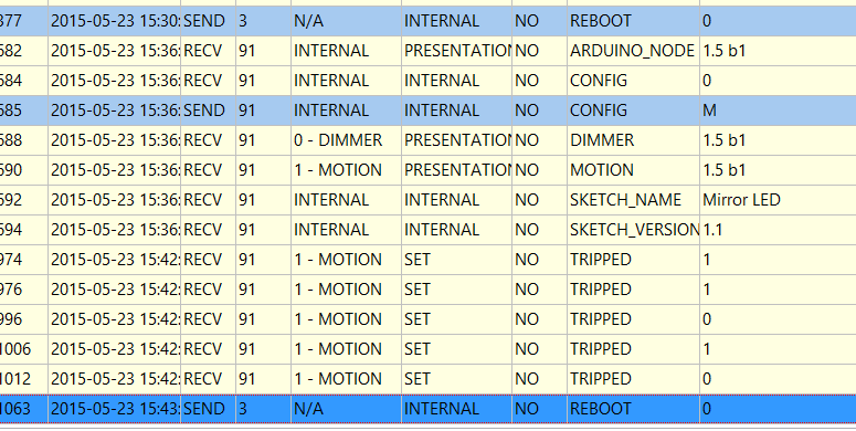
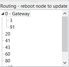
  • @tekka See below it reboot the first time when I try it the seconde time it did
    not it just say reboot

    upload-c74f717f-972d-42a4-8346-7dac5fd0bc3a

    Here is my routing Tabel:

    upload-eab02958-9c75-4343-b325-7578209d761f


  • Admin

    @Francois the node has AUTO ID or fix assigned ID (i.e. 91?) - if so, this may be an issue in the dev branch


  • Hero Member

    Anyone who owns a Vera controller, and perhaps was able to connect this nice MYSController to the mySensors serial-gateway hooked into Vera USB?

    The serial port is exposed in TCP/IP by Vera via ser2net, however I wasn't successful by setting MYSController to <my-vera-ip>:3482 (3482 is the port displayed in Vera -> APPS -> Develop Apps -> Serial port config ) .

    (maybe the Vera MYSensor plugin opens the serial connection to GW in 'exclusive' mode or something like that? )

    If I remove the GW from Vera USB and plug in my computer, MYSController works fine.

    Anyone? Am I wanting too much?


  • I'm new to MySensors and playing around with this implementation since some weeks. I implemented an interface from serial to MQTT per python and everything is running fine so far. The last days I spend some time with the bootloader (it is a great feature!!!). I created also a python mqtt client that will take care on that.

    I got really crazy the last 2 days with the CRC calculation. I always got a different CRC as as the MYSController. Now I found out, that it seems that the last byte within the HEX file is interpreted as 0xFF instead of the real data. I flashed now one sensor with the MYSController and as I can see in the log-file -> the last byte is read from the HEX as wrong value (0xFF instead of 0x14) -> therefore the HEX file is not flashed correctly (last byte is wrong) -> it seems that this is a bug in MYSController. (I'm using version 0.1.2.278)

    Can you check that please?


  • Admin

    @JoergP Indeed, bug confirmed. There is an error in the block padding code. I will push the update soon. Thanks for reporting!


  • Hello,

    First of all, thanks Tekka for the great MYScontroller!

    I want to get started with the MYSbootloader but I can't get it to work. I've followed each step securely but I never "see" my arduino in MYScontroller after flashing the bootloader. Perhaps I misunderstand the theory behind the bootloader? Maybe the fuses are wrong, I don't know.

    Perhaps someone can reply to the following;

    • Can I just attach a radio module to an Arduino Nano as instructed on the site, clear the eeprom and then burn the bootloader using usbasp? (as instructed in this thread) Or do I need to upload the gateway sketch before burning the bootloader?
    • I have a hard time understanding what the bootloader does, I think it enables low level nrf functionality for OTA and Myscontroller instructions like reboot and clear eeprom etc. But when I upload a sketch does that mean the bootloader inits the nrf first and then the uploaded sketch will just re-init the nrf again?
    • Is there a way to debug the bootloader?

    Have a good laugh if you will at these noob questions, but any help is appreciated 🙂


  • Admin

    @cdr said:

    • Can I just attach a radio module to an Arduino Nano as instructed on the site, clear the eeprom and then burn the bootloader using usbasp? (as instructed in this thread) Or do I need to upload the gateway sketch before burning the bootloader?

    Yes, simply attach the radio and burn the bootloader with the correct fuse settings (see the fuses.txt file in the bootloader directory). If you intend to use MYSController, set AutoID to automatically assign IDs to the nodes.

    • I have a hard time understanding what the bootloader does, I think it enables low level nrf functionality for OTA and Myscontroller instructions like reboot and clear eeprom etc. But when I upload a sketch does that mean the bootloader inits the nrf first and then the uploaded sketch will just re-init the nrf again?

    Yes, that's correct. The bootloader is a small piece of code located at the end of the flash area that is (if the fuses are set accordingly) executed first upon rebooting and allows for low-level OTA updates.

    • Is there a way to debug the bootloader?

    Yes, there are several ways (e.g. visual with LED, serial output, or AVR DebugWire)...you may want to google these topics for further information..

    Have a good laugh if you will at these noob questions, but any help is appreciated 🙂

    no problem 🙂


  • Hi tekka,

    Thanks for the response and clarification. I think I need more knowledge about fuses and bootloaders, it could be that the arduino clones are giving me sh&t.

    Looking forward to my success and MYSloader 2.0 ofcourse!

    Thanks again for all your work.


  • Admin

    MYSController Version 0.1.2.280 released

    Changelog:

    • Bugfix FW padding (thanks @JoergP)
    • Handler rework
    • Logging format rework
    • Support battery-powered/sleeping nodes
    • Refactoring

    Update via update button in MYSController or download here.


  • This is the most helpful tool I used since I started messing around with mysensors.

    I hate to nag but this tool source code would be a giant step to someone looking to create a new controller by himself.
    .


  • Hello, how to verify right bootloader is uploaded to arduino?

    I'm using two Arduino Pro Mini 328 5.0V 16Mhz, one as ArduinoISP programmer and one as sensor node to upload bootloader and firmware.

    I followed manual (http://forum.mysensors.org/topic/838/windows-gui-controller-for-mysensors/76) step by step.

    I have tried MYSBootloader.hex coming from latest MYSController 0.1.2.280 and MYSBootloader.hex (1.1) from github with same results.

    Upload log is here:

    C:\Program Files (x86)\Arduino\hardware\tools\avr/bin/avrdude -CC:\Program Files (x86)\Arduino\hardware\tools\avr/etc/avrdude.conf -v -patmega328p -cstk500v1 -PCOM10 -b19200 -e -Ulock:w:0x3F:m -Uefuse:w:0x06:m -Uhfuse:w:0xDA:m -Ulfuse:w:0xF7:m 
    
    avrdude: Version 6.0.1, compiled on Apr 15 2015 at 19:59:58
             Copyright (c) 2000-2005 Brian Dean, http://www.bdmicro.com/
             Copyright (c) 2007-2009 Joerg Wunsch
    
             System wide configuration file is "C:\Program Files (x86)\Arduino\hardware\tools\avr/etc/avrdude.conf"
    
             Using Port                    : COM10
             Using Programmer              : stk500v1
             Overriding Baud Rate          : 19200
             AVR Part                      : ATmega328P
             Chip Erase delay              : 9000 us
             PAGEL                         : PD7
             BS2                           : PC2
             RESET disposition             : dedicated
             RETRY pulse                   : SCK
             serial program mode           : yes
             parallel program mode         : yes
             Timeout                       : 200
             StabDelay                     : 100
             CmdexeDelay                   : 25
             SyncLoops                     : 32
             ByteDelay                     : 0
             PollIndex                     : 3
             PollValue                     : 0x53
             Memory Detail                 :
    
                                      Block Poll               Page                       Polled
               Memory Type Mode Delay Size  Indx Paged  Size   Size #Pages MinW  MaxW   ReadBack
               ----------- ---- ----- ----- ---- ------ ------ ---- ------ ----- ----- ---------
               eeprom        65    20     4    0 no       1024    4      0  3600  3600 0xff 0xff
               flash         65     6   128    0 yes     32768  128    256  4500  4500 0xff 0xff
               lfuse          0     0     0    0 no          1    0      0  4500  4500 0x00 0x00
               hfuse          0     0     0    0 no          1    0      0  4500  4500 0x00 0x00
               efuse          0     0     0    0 no          1    0      0  4500  4500 0x00 0x00
               lock           0     0     0    0 no          1    0      0  4500  4500 0x00 0x00
               calibration    0     0     0    0 no          1    0      0     0     0 0x00 0x00
               signature      0     0     0    0 no          3    0      0     0     0 0x00 0x00
    
             Programmer Type : STK500
             Description     : Atmel STK500 Version 1.x firmware
             Hardware Version: 2
             Firmware Version: 1.18
             Topcard         : Unknown
             Vtarget         : 0.0 V
             Varef           : 0.0 V
             Oscillator      : Off
             SCK period      : 0.1 us
    
    avrdude: AVR device initialized and ready to accept instructions
    
    Reading | ################################################## | 100% 0.05s
    
    avrdude: Device signature = 0x1e950f
    avrdude: erasing chip
    avrdude: reading input file "0x3F"
    avrdude: writing lock (1 bytes):
    
    Writing | ################################################## | 100% 0.03s
    
    avrdude: 1 bytes of lock written
    avrdude: verifying lock memory against 0x3F:
    avrdude: load data lock data from input file 0x3F:
    avrdude: input file 0x3F contains 1 bytes
    avrdude: reading on-chip lock data:
    
    Reading | ################################################## | 100% 0.02s
    
    avrdude: verifying ...
    avrdude: 1 bytes of lock verified
    avrdude: reading input file "0x06"
    avrdude: writing efuse (1 bytes):
    
    Writing | ################################################## | 100% 0.02s
    
    avrdude: 1 bytes of efuse written
    avrdude: verifying efuse memory against 0x06:
    avrdude: load data efuse data from input file 0x06:
    avrdude: input file 0x06 contains 1 bytes
    avrdude: reading on-chip efuse data:
    
    Reading | ################################################## | 100% 0.01s
    
    avrdude: verifying ...
    avrdude: 1 bytes of efuse verified
    avrdude: reading input file "0xDA"
    avrdude: writing hfuse (1 bytes):
    
    Writing | ################################################## | 100% 0.03s
    
    avrdude: 1 bytes of hfuse written
    avrdude: verifying hfuse memory against 0xDA:
    avrdude: load data hfuse data from input file 0xDA:
    avrdude: input file 0xDA contains 1 bytes
    avrdude: reading on-chip hfuse data:
    
    Reading | ################################################## | 100% 0.02s
    
    avrdude: verifying ...
    avrdude: 1 bytes of hfuse verified
    avrdude: reading input file "0xF7"
    avrdude: writing lfuse (1 bytes):
    
    C:\Program Files (x86)\Arduino\hardware\tools\avr/bin/avrdude -CC:\Program Files (x86)\Arduino\hardware\tools\avr/etc/avrdude.conf -v -patmega328p -cstk500v1 -PCOM10 -b19200 -Uflash:w:C:\Program Files (x86)\Arduino\hardware\arduino\avr/bootloaders/MySensors/MYSBootloader.hex:i -Ulock:w:0x0F:m 
    
    avrdude: Version 6.0.1, compiled on Apr 15 2015 at 19:59:58
             Copyright (c) 2000-2005 Brian Dean, http://www.bdmicro.com/
             Copyright (c) 2007-2009 Joerg Writing | ################################################## | 100% 0.02s
    
    avrdude: 1 bytes of lfuse written
    avrdude: verifying lfuse memory against 0xF7:
    avrdude: load data lfuse data from input file 0xF7:
    avrdude: input file 0xF7 contains 1 bytes
    avrdude: reading on-chip lfuse data:
    
    Reading | ################################################## | 100% 0.02s
    
    avrdude: verifying ...
    avrdude: 1 bytes of lfuse verified
    
    avrdude done.  Thank you.
    
    Wunsch
    
             System wide configuration file is "C:\Program Files (x86)\Arduino\hardware\tools\avr/etc/avrdude.conf"
    
             Using Port                    : COM10
             Using Programmer              : stk500v1
             Overriding Baud Rate          : 19200
             AVR Part                      : ATmega328P
             Chip Erase delay              : 9000 us
             PAGEL                         : PD7
             BS2                           : PC2
             RESET disposition             : dedicated
             RETRY pulse                   : SCK
             serial program mode           : yes
             parallel program mode         : yes
             Timeout                       : 200
             StabDelay                     : 100
             CmdexeDelay                   : 25
             SyncLoops                     : 32
             ByteDelay                     : 0
             PollIndex                     : 3
             PollValue                     : 0x53
             Memory Detail                 :
    
                                      Block Poll               Page                       Polled
               Memory Type Mode Delay Size  Indx Paged  Size   Size #Pages MinW  MaxW   ReadBack
               ----------- ---- ----- ----- ---- ------ ------ ---- ------ ----- ----- ---------
               eeprom        65    20     4    0 no       1024    4      0  3600  3600 0xff 0xff
               flash         65     6   128    0 yes     32768  128    256  4500  4500 0xff 0xff
               lfuse          0     0     0    0 no          1    0      0  4500  4500 0x00 0x00
               hfuse          0     0     0    0 no          1    0      0  4500  4500 0x00 0x00
               efuse          0     0     0    0 no          1    0      0  4500  4500 0x00 0x00
               lock           0     0     0    0 no          1    0      0  4500  4500 0x00 0x00
               calibration    0     0     0    0 no          1    0      0     0     0 0x00 0x00
               signature      0     0     0    0 no          3    0      0     0     0 0x00 0x00
    
             Programmer Type : STK500
             Description     : Atmel STK500 Version 1.x firmware
             Hardware Version: 2
             Firmware Version: 1.18
             Topcard         : Unknown
             Vtarget         : 0.0 V
             Varef           : 0.0 V
             Oscillator      : Off
             SCK period      : 0.1 us
    
    avrdude: AVR device initialized and ready to accept instructions
    
    Reading | ################################################## | 100% 0.06s
    
    avrdude: Device signature = 0x1e950f
    avrdude: NOTE: "flash" memory has been specified, an erase cycle will be performed
             To disable this feature, specify the -D option.
    avrdude: erasing chip
    avrdude: reading input file "C:\Program Files (x86)\Arduino\hardware\arduino\avr/bootloaders/MySensors/MYSBootloader.hex"
    avrdude: writing flash (32722 bytes):
    
    Writing | ################################################## | 100% -0.00s
    
    avrdude: 32722 bytes of flash written
    avrdude: verifying flash memory against C:\Program Files (x86)\Arduino\hardware\arduino\avr/bootloaders/MySensors/MYSBootloader.hex:
    avrdude: load data flash data from input file C:\Program Files (x86)\Arduino\hardware\arduino\avr/bootloaders/MySensors/MYSBootloader.hex:
    avrdude: input file C:\Program Files (x86)\Arduino\hardware\arduino\avr/bootloaders/MySensors/MYSBootloader.hex contains 32722 bytes
    avrdude: reading on-chip flash data:
    
    Reading | ################################################## | 100% 0.02s
    
    avrdude: verifying ...
    avrdude: 32722 bytes of flash verified
    avrdude: reading input file "0x0F"
    avrdude: writing lock (1 bytes):
    
    Writing | ################################################## | 100% 0.05s
    
    avrdude: 1 bytes of lock written
    avrdude: verifying lock memory against 0x0F:
    avrdude: load data lock data from input file 0x0F:
    avrdude: input file 0x0F contains 1 bytes
    avrdude: reading on-chip lock data:
    
    Reading | ################################################## | 100% 0.01s
    
    avrdude: verifying ...
    avrdude: 1 bytes of lock verified
    
    avrdude done.  Thank you.


    Fuses looks like right:

    avrdude: Device signature = 0x1e950f
    avrdude: safemode: lfuse reads as F7
    avrdude: safemode: hfuse reads as DA
    avrdude: safemode: efuse reads as 6
    

    MYSController log after node with new bootloader start:

    14.06.2015 10:14:46	STARTUP	Initialize message logging
    14.06.2015 10:14:46	STARTUP	MYSController 0.1.2.280
    14.06.2015 10:14:46	STARTUP	FPC 2.6.4 / Lazarus 1.4
    14.06.2015 10:14:46	STARTUP	still under development :) tekka 2015
    14.06.2015 10:14:46	STARTUP	Load INI file...
    14.06.2015 10:14:46	STARTUP	INI version 0.1.2.280
    14.06.2015 10:14:46	INFO	*** Logging START ***
    14.06.2015 10:14:46	VERSION	MYSController 0.1.2.280
    14.06.2015 10:14:46	STARTUP	INI file loaded
    14.06.2015 10:14:46	STARTUP	Loading FW repository...
    14.06.2015 10:14:46	REPO	FW "Blink" loaded. t=10, v=1, blocks=72, crc=0xD098
    14.06.2015 10:14:46	REPO	FW "TimeReporter" loaded. t=20, v=1, blocks=840, crc=0x4AC5
    14.06.2015 10:14:46	REPO	FW repository loaded. Items=2
    14.06.2015 10:14:46	STARTUP	Initialize message types
    14.06.2015 10:14:46	NODE	New node discovered, node id=0
    14.06.2015 10:14:46	NODE	New node discovered, node id=255
    14.06.2015 10:14:49	INFO	Connected to 192.168.0.1:12345
    14.06.2015 10:14:59	UPDATE	4295098648
    14.06.2015 10:21:26	CHILD	New child discovered, node id=0, child id=0
    14.06.2015 10:21:26	RX	0;0;3;0;9;read: 255-255-255 s=255,c=3,t=7,pt=0,l=0,sg=0:
    14.06.2015 10:21:26	RX	0;0;3;0;9;send: 0-0-255-255 s=255,c=3,t=8,pt=1,l=1,sg=0,st=bc:0
    14.06.2015 10:21:28	RX	0;0;3;0;9;read: 3-3-255 s=255,c=3,t=7,pt=0,l=0,sg=0:
    14.06.2015 10:21:28	RX	0;0;3;0;9;send: 0-0-3-3 s=255,c=3,t=8,pt=1,l=1,sg=0,st=ok:0
    14.06.2015 10:21:30	RX	0;0;3;0;9;read: 3-3-0 s=255,c=3,t=6,pt=1,l=1,sg=0:0
    14.06.2015 10:21:30	NODE	New node discovered, node id=3
    14.06.2015 10:21:30	CHILD	New child discovered, node id=3, child id=internal
    14.06.2015 10:21:30	TX	3;255;3;0;6;M
    14.06.2015 10:21:30	RX	3;255;3;0;6;0
    14.06.2015 10:21:30	RX	0;0;3;0;9;send: 0-0-3-3 s=255,c=3,t=6,pt=0,l=1,sg=0,st=ok:M
    14.06.2015 10:21:32	RX	0;0;3;0;9;read: 3-3-0 s=255,c=3,t=11,pt=0,l=7,sg=0:Balcony
    14.06.2015 10:21:32	RX	3;255;3;0;11;Balcony
    14.06.2015 10:21:32	RX	0;0;3;0;9;read: 3-3-0 s=255,c=3,t=12,pt=0,l=3,sg=0:1.0
    14.06.2015 10:21:32	RX	3;255;3;0;12;1.0
    14.06.2015 10:21:32	RX	0;0;3;0;9;read: 3-3-0 s=1,c=0,t=16,pt=0,l=20,sg=0:Photoconductive Cel
    14.06.2015 10:21:32	CHILD	New child discovered, node id=3, child id=1
    14.06.2015 10:21:32	DEBUG	Update child id=1, type=LIGHT_LEVEL
    14.06.2015 10:21:32	RX	3;1;0;0;16;Photoconductive Cell
    14.06.2015 10:21:32	RX	0;0;3;0;9;read: 3-3-0 s=2,c=0,t=6,pt=0,l=3,sg=0:ds0
    14.06.2015 10:21:32	CHILD	New child discovered, node id=3, child id=2
    14.06.2015 10:21:32	DEBUG	Update child id=2, type=TEMP
    14.06.2015 10:21:32	RX	3;2;0;0;6;ds0
    14.06.2015 10:21:32	RX	0;0;3;0;9;read: 3-3-0 s=3,c=0,t=6,pt=0,l=3,sg=0:ds1
    14.06.2015 10:21:32	CHILD	New child discovered, node id=3, child id=3
    14.06.2015 10:21:32	DEBUG	Update child id=3, type=TEMP
    14.06.2015 10:21:32	RX	3;3;0;0;6;ds1
    14.06.2015 10:21:32	RX	0;0;3;0;9;read: 3-3-0 s=4,c=0,t=6,pt=0,l=3,sg=0:ds2
    14.06.2015 10:21:32	CHILD	New child discovered, node id=3, child id=4
    14.06.2015 10:21:32	DEBUG	Update child id=4, type=TEMP
    14.06.2015 10:21:32	RX	3;4;0;0;6;ds2
    14.06.2015 10:21:32	RX	0;0;3;0;9;read: 3-3-0 s=5,c=0,t=6,pt=0,l=3,sg=0:ds3
    14.06.2015 10:21:32	CHILD	New child discovered, node id=3, child id=5
    14.06.2015 10:21:32	DEBUG	Update child id=5, type=TEMP
    14.06.2015 10:21:32	RX	3;5;0;0;6;ds3
    14.06.2015 10:21:33	RX	0;0;3;0;9;read: 3-3-0 s=6,c=0,t=6,pt=0,l=3,sg=0:ds4
    14.06.2015 10:21:33	CHILD	New child discovered, node id=3, child id=6
    14.06.2015 10:21:33	DEBUG	Update child id=6, type=TEMP
    14.06.2015 10:21:33	RX	3;6;0;0;6;ds4
    14.06.2015 10:21:33	RX	0;0;3;0;9;read: 3-3-0 s=7,c=0,t=6,pt=0,l=3,sg=0:ds5
    14.06.2015 10:21:33	CHILD	New child discovered, node id=3, child id=7
    14.06.2015 10:21:33	DEBUG	Update child id=7, type=TEMP
    14.06.2015 10:21:33	RX	3;7;0;0;6;ds5
    14.06.2015 10:21:33	RX	0;0;3;0;9;read: 3-3-0 s=8,c=0,t=6,pt=0,l=3,sg=0:ds6
    14.06.2015 10:21:33	CHILD	New child discovered, node id=3, child id=8
    14.06.2015 10:21:33	DEBUG	Update child id=8, type=TEMP
    14.06.2015 10:21:33	RX	3;8;0;0;6;ds6
    14.06.2015 10:21:33	RX	0;0;3;0;9;read: 3-3-0 s=9,c=0,t=6,pt=0,l=3,sg=0:ds7
    14.06.2015 10:21:33	CHILD	New child discovered, node id=3, child id=9
    14.06.2015 10:21:33	DEBUG	Update child id=9, type=TEMP
    14.06.2015 10:21:33	RX	3;9;0;0;6;ds7
    14.06.2015 10:21:33	RX	0;0;3;0;9;read: 3-3-0 s=10,c=0,t=6,pt=0,l=3,sg=0:ds8
    14.06.2015 10:21:33	CHILD	New child discovered, node id=3, child id=10
    14.06.2015 10:21:33	DEBUG	Update child id=10, type=TEMP
    14.06.2015 10:21:33	RX	3;10;0;0;6;ds8
    14.06.2015 10:21:33	RX	0;0;3;0;9;read: 3-3-0 s=11,c=0,t=6,pt=0,l=3,sg=0:ds9
    14.06.2015 10:21:33	CHILD	New child discovered, node id=3, child id=11
    14.06.2015 10:21:33	DEBUG	Update child id=11, type=TEMP
    14.06.2015 10:21:33	RX	3;11;0;0;6;ds9
    14.06.2015 10:21:33	RX	0;0;3;0;9;read: 3-3-0 s=1,c=1,t=23,pt=2,l=2,sg=0:49
    14.06.2015 10:21:33	RX	3;1;1;0;23;49
    14.06.2015 10:21:36	RX	0;0;3;0;9;read: 3-3-0 s=3,c=1,t=0,pt=7,l=5,sg=0:26.5625
    14.06.2015 10:21:36	RX	3;3;1;0;0;26.5625
    14.06.2015 10:21:37	RX	0;0;3;0;9;read: 3-3-0 s=1,c=1,t=23,pt=2,l=2,sg=0:49
    14.06.2015 10:21:37	RX	3;1;1;0;23;49
    

    Node successfully start and connecting to gateway with new bootloader, but then I issue reboot command in MYSController, node hangs up completely, even reset button isn't working. Only power off, then power on helps. Assign firmware isn't working also (nothing happens).


  • Admin

    @robosensor said:

    The MYSBootloader.hex file you are flashing has a wrong file size (=32722 bytes) in your post:

    avrdude: reading input file "C:\Program Files (x86)\Arduino\hardware\arduino\avr/bootloaders/MySensors/MYSBootloader.hex"
    avrdude: writing flash (32722 bytes):

    MYSBootloader 1.1 should have ~2kb

    From your log I assume, that you flashed the sketch instead of the bootloader.

    Please pay attention to steps 3 and 13 from the step-by-step manual.


  • @tekka I have noticed this, but I thought that this is due to the peculiarities of bootloader upload process (upper end of memory).

     Directory of C:\Program Files (x86)\Arduino\hardware\arduino\avr\bootloaders\MySensors
    
    14.06.2015  00:08    <DIR>          .
    14.06.2015  00:08    <DIR>          ..
    14.06.2015  09:59             5 548 MYSBootloader.hex
                   1 File(s)          5 548 bytes
    

    For sketch size is too big (32722 bytes), real sketch size is 19928 bytes.

    In any case, thanks for the help, I'll try to figure it out or try to download it manually using avrdude.


  • @tekka
    Hello, could you help me with uploading bootloader. I stuck on Step 5 step-by-step manual and get error

    Arduino: 1.6.4 (Mac OS X), Плата"ATmega328 16Mhz MYSBootloader"
    avrdude: error: could not find USB device with vid=0x16c0 pid=0x5dc vendor='www.fischl.de' product='USBasp'


    I`m using 16Mhz pro mini clone and FTDI232


  • @tekka I have googled for [avrdude bootloader "bytes of flash written"] and found many answers about big upload size for bootloader (> 32000 bytes). It seems that big size is the way it should be.

    I have solved problem. I must power up node with newly burned bootloader but without sensor node firmware and upload firmware using MYSController

    Incorrect way is: burn bootloader, burn sensor node firmware, powerup sensor.

    Thank you for great software! 🙂


  • Admin

    @NewFolk You'll need e.g. USBasp or ArduinoISP to flash a new bootloader. If you have a spare Arduino and FTDI232, follow this tutorial to program a new bootloader using the Arduino IDE.

    Good luck! 🙂


  • Admin

    @robosensor Yes, the sensor firmware is uploaded OTA via MYSController.


  • Hi - I need some clarification.
    I have mysensors connected to my vera lite (working)
    I bought 3 of the sensebender micro boards and got them talking with the gateway (working)
    loaded up myscontroller it's running and see the gateway and all 3 nodes.
    yay!
    the issue is the sensors are reporting in C instead of F, so i modified the sketch, compiled it, found the hex file (66k)
    and moved it to the correct folder per instructions.
    when i says "assign FW" nothing happens.
    am i understanding correctly that "firmware" is just a compiled sketch?
    if i need to make changes to my device, is this the correct way?
    modify sketch - > compile -> move hex to myscontroller folder - > edit firmware_config file -> right click assign fw -> pick new firmware
    is that correct?
    nothing is happening for me when i do that..
    please clarify.
    thanks!

    edit: file size says 66k in win7
    but in the compiler it says
    Sketch uses 23,724 bytes (77%) of program storage space. Maximum is 30,720 bytes.
    Global variables use 822 bytes (40%) of dynamic memory, leaving 1,226 bytes for local variables. Maximum is 2,048 bytes.

    the file i grabbed was SensebenderMicro.cpp.hex


  • Admin

    @mvader said:

    when i says "assign FW" nothing happens.
    am i understanding correctly that "firmware" is just a compiled sketch?
    if i need to make changes to my device, is this the correct way?
    modify sketch - > compile -> move hex to myscontroller folder - > edit firmware_config file -> right click assign fw -> pick new firmware
    is that correct?
    nothing is happening for me when i do that..

    For OTA updates you need to burn the MYSBootloader (instructions here). Once done, assign FW, reboot node and wait until FW is transferred.

    edit: file size says 66k in win7
    but in the compiler it says
    Sketch uses 23,724 bytes (77%) of program storage space. Maximum is 30,720 bytes.

    Yup, because the .hex file is not binary but a hex (hence the suffix) format with headers and checksums.


  • @tekka said:

    @mvader said:

    when i says "assign FW" nothing happens.
    am i understanding correctly that "firmware" is just a compiled sketch?
    if i need to make changes to my device, is this the correct way?
    modify sketch - > compile -> move hex to myscontroller folder - > edit firmware_config file -> right click assign fw -> pick new firmware
    is that correct?
    nothing is happening for me when i do that..

    For OTA updates you need to burn the MYSBootloader (instructions here). Once done, assign FW, reboot node and wait until FW is transferred.

    edit: file size says 66k in win7
    but in the compiler it says
    Sketch uses 23,724 bytes (77%) of program storage space. Maximum is 30,720 bytes.

    Yup, because the .hex file is not binary but a hex (hence the suffix) format with headers and checksums.

    I thought i read those sensebender boards were going to come pre-burned with the MYSBootloader from the mfg? that why you wouldn't need a programmer. i'll check with those folks..

    edit: i found where they said it was pre-programmed..

    @hek said:

    Yes, FTDI, ISCP or over-the-air updates.

    It comes pre-programmed with MySensors variant of the DualOptiboot-bootloader.
    https://github.com/mysensors/DualOptiboot
    Which can take advantage of the extra flash memory to do a safe over-the-air firmware update.
    It comes pre-programmed with MySensors variant of the DualOptiboot-bootloader.
    https://github.com/mysensors/DualOptiboot
    Which can take advantage of the extra flash memory to do a safe over-the-air firmware update.


  • This post is deleted!


  • I have a some questions. Couldnt find answer anywhere.

    If I am using an arduino connected to the serial port on a Raspberry pi (w/openhab) How do I assign fw, reboot, etc?

    Do I need to disconnect the GW and use windows temporarily to reboot, update fw? or can I have 2 GW's?

    I updated my nano with the MYS bootloader, and after I power it on, it never shows up in MYSController.


  • @tekka Hey, it seems like the downloadlink is broken. Can you check?


  • i dont understand how to use this...
    Can somebody explain it?


  • Admin


  • Yes I tried now again an now it works. Maybe something temporary with Dropbox yesterday


  • It is possible to burn the bootloader to an Arduino Uno right? (if not please skip below and I will rtfm some more)

    Could anyone please explain me what I am doing wrong here? I use avrdudess (http://blog.zakkemble.co.uk/avrdudess-a-gui-for-avrdude/) to program the bootloader.hex (also tried the supplied method) but no dice;

    Writing the bootloader seems to work;

    Detected 1e950f = ATmega328P
    MYSBootloader.hex: 2.002 / 32.768 Bytes (6,11%)
    ~ ~ ~ ~ ~ ~ ~ ~ ~ ~ ~ ~ ~ ~ ~ ~ 
    
    avrdude.exe: set SCK frequency to 1500000 Hz
    avrdude.exe: warning: cannot set sck period. please check for usbasp firmware update.
    avrdude.exe: AVR device initialized and ready to accept instructions
    
    Reading | ################################################## | 100% 0.00s
    
    avrdude.exe: Device signature = 0x1e950f
    avrdude.exe: erasing chip
    avrdude.exe: set SCK frequency to 1500000 Hz
    avrdude.exe: warning: cannot set sck period. please check for usbasp firmware update.
    avrdude.exe: reading input file "C:\Users\codar\Desktop\MYSController_0_1_2_280\Bootloader\MYSBootloader.hex"
    avrdude.exe: input file C:\Users\codar\Desktop\MYSController_0_1_2_280\Bootloader\MYSBootloader.hex auto detected as Intel Hex
    avrdude.exe: writing flash (32722 bytes):
    
    Writing | ################################################## | 100% 0.00s
    
    avrdude.exe: 32722 bytes of flash written
    avrdude.exe: verifying flash memory against C:\Users\codar\Desktop\MYSController_0_1_2_280\Bootloader\MYSBootloader.hex:
    avrdude.exe: load data flash data from input file C:\Users\codar\Desktop\MYSController_0_1_2_280\Bootloader\MYSBootloader.hex:
    avrdude.exe: input file C:\Users\codar\Desktop\MYSController_0_1_2_280\Bootloader\MYSBootloader.hex auto detected as Intel Hex
    avrdude.exe: input file C:\Users\codar\Desktop\MYSController_0_1_2_280\Bootloader\MYSBootloader.hex contains 32722 bytes
    avrdude.exe: reading on-chip flash data:
    
    Reading | ################################################## | 100% 0.00s
    
    avrdude.exe: verifying ...
    avrdude.exe: 32722 bytes of flash verified
    

    However tech life wouldn't be techlife without days of endless debugging

    Setting the extended fuse fails verification

    avrdude.exe: reading on-chip flash data:
    
    Reading | ################################################## | 100% 0.00s
    
    avrdude.exe: verifying ...
    avrdude.exe: 32722 bytes of flash verified
    avrdude.exe: reading input file "0xF7"
    avrdude.exe: writing lfuse (1 bytes):
    
    Writing | ################################################## | 100% 0.00s
    
    avrdude.exe: 1 bytes of lfuse written
    avrdude.exe: verifying lfuse memory against 0xF7:
    avrdude.exe: load data lfuse data from input file 0xF7:
    avrdude.exe: input file 0xF7 contains 1 bytes
    avrdude.exe: reading on-chip lfuse data:
    
    Reading | ################################################## | 100% 0.00s
    
    avrdude.exe: verifying ...
    avrdude.exe: 1 bytes of lfuse verified
    avrdude.exe: reading input file "0xDA"
    avrdude.exe: writing hfuse (1 bytes):
    
    Writing | ################################################## | 100% 0.00s
    
    avrdude.exe: 1 bytes of hfuse written
    avrdude.exe: verifying hfuse memory against 0xDA:
    avrdude.exe: load data hfuse data from input file 0xDA:
    avrdude.exe: input file 0xDA contains 1 bytes
    avrdude.exe: reading on-chip hfuse data:
    
    Reading | ################################################## | 100% 0.00s
    
    avrdude.exe: verifying ...
    avrdude.exe: 1 bytes of hfuse verified
    avrdude.exe: reading input file "0xFE"
    avrdude.exe: writing efuse (1 bytes):
    
    Writing |  ***failed;  
    ################################################## | 100% 0.03s
    
    avrdude.exe: 1 bytes of efuse written
    avrdude.exe: verifying efuse memory against 0xFE:
    avrdude.exe: load data efuse data from input file 0xFE:
    avrdude.exe: input file 0xFE contains 1 bytes
    avrdude.exe: reading on-chip efuse data:
    
    Reading | ################################################## | 100% 0.00s
    
    avrdude.exe: verifying ...
    avrdude.exe: verification error, first mismatch at byte 0x0000
                 0x06 != 0xfe
    avrdude.exe: verification error; content mismatch
    
    avrdude.exe done.  Thank you.
    

    This last error is giving me headaches, why the "first mismatch at byte 0x0000 0x06 != 0xfe" error?

    Really hope someone can enlighten me...


  • Admin

    @cdr the efuse only uses the lower 3 bits: with AVRDude set 0x06, with AVRStudio set 0xFE. You can verify this with the fuse calculator.


  • I try to uplaod sketch via OTA but it doesn''t work.
    I have sensebender with stock bootloader. Gateway is connect to an ODROID C1 with ser2net and i connect to ser2net. I can see all incoming traffic for my sensors.
    I upload sensebender default sketch from dev branch using MySensors dev branch too.
    I tell MYSController sensors is battery powered.
    I try with the two provided example but nothing happen in log or anything else


  • @Fabien said:

    I try to uplaod sketch via OTA but it doesn''t work.
    I have sensebender with stock bootloader. Gateway is connect to an ODROID C1 with ser2net and i connect to ser2net. I can see all incoming traffic for my sensors.
    I upload sensebender default sketch from dev branch using MySensors dev branch too.
    I tell MYSController sensors is battery powered.
    I try with the two provided example but nothing happen in log or anything else

    check in the sensebender announcement thread. I had the same question. Hek responded with what needed to be done to make it work.
    I didn't get a chance to try his solutions yet to see if it works. if you do, post and let us know.

    edit: here
    http://forum.mysensors.org/topic/1345/sensebender-micro/139


  • Contest Winner

    @Fabien
    I dont understand what you mean by "I told MysController" that the node is battery powered. It should find that out automatically I think. Anyway I'm pretty sure that I read somewhere that battery powered sensors cant be updated OTA. (If it relly is battery powered). I think I read a define somewhere that disables the firmware low level commands in the MySensors Library if the Node is battery powered.


  • Admin

    @Dirk_H said:

    I think I read a define somewhere that disables the firmware low level commands in the MySensors Library if the Node is battery powered.

    No there isn't. But battery powered sensors most likely sleep most of the time so they won't receive any update command. And a fw updates over-the-air would probably drain batteries pretty quick.


  • @tekka I feel really, really, REALLY stupid;

    I changed the channel in the mysensors config.h to 77, this was the reason no node would ever show up since the default mysbootloader uses the default channel 76.

    D'OH

    Thanks for your patience and help, everything is working now and I'm really happy!
    👍


  • Hi. I was wondering if someone could get the irrigation controller working with this program?
    I'm new to this all, and so far this the easiest controller that I came across. ( got the gateway etc working with almost no effort)


  • Hi, nice work. Is there any chances that you add the possibility to log the nodes information to a mysql database ?


  • Hi @tekka
    I am having trouble understanding the error codes on this gui.

    It is the solar mini weather stn on proto board and it is not working properly.

    At this minute I see that the g/w code is telling me 4-4-5-0 ,there was a node 5 in my My Sensors package and it was configured as a repeater but it is not here as it connected laptop> usb port/cord> ftdi 3.3v> 3.3 v promini.
    As the code cannot get to and from node 5 it is a down as a st=fail

    Is there a why to change this in your program to allow continuing debugging my sketch?

    Am I again missing something?
    Thanks


  • Sorry @tekka forgot the pic.Screenshot (62).png


  • Admin

    @5546dug the log looks like a sensor log, try connecting MYSController to the gateway...


  • Hero Member

    Hello guys, I'm trying to burn the MYSBootloader.hex into some Pro minis (clones) here, however after burning it, they get somehow 'bricked' :

    • I'm using my Uno "as ISP" on IDE 1.6.4
    • I've followed the step-by-step tutorial posted above by @tekka
    • My pro-minis are 5V, 16Mhz, external clock , 328p, supposedly a perfect match with 'boards.txt' info...
    • "Burn bootloader" ends successful, with "Done burning boot loader" message.
    • After that, the pro-mini pin 13 led flashes in a kind of random pattern, and it is not possible to upload any sketch, nor any kind of serial monitor on any speed.
    • I can revert it, by selecting the standard 'Arduino Pro or Pro Mini' board , and burn boot loader again. It makes the pro-mini gets back to live, I can upload my sketches and serial monitor it.

    So my questions:

    • I don't have extra eprom connected --- Is it mandatory? I've read somewhere that it can be disabled, but can't find the instructions anymore...
    • Fuse adjustments?
    • What else can I do in order to troubleshooting it?

    Thanks!


  • Hardware Contributor

    @rvendrame: it seems to be wrong fuses. MYSBootloader does not use extra eeprom. It's DualOptiboot which uses one. You need to set fuses. Then burn bootloader. For fuses you need to look in boards.txt . It should work. For setting fuses, I use usbasp. I never tried with uno.


  • Hero Member

    @scalz, thanks for the reply. BTW, did you see this?

    Well, with standard bootloader (working), my pro-minis have fuses as FF DA 05 (Low/High/Ext).

    The MYSBootloader.hex boot loader (not working) is set in boards.txt with F7 DA 06.

    I have played with all possible combinations (including changing values in boards.txt), no luck.

    Maybe I have to compile my own version of MYSBootloader? Sorry, this is all new to me...

    Thx again


  • Hardware Contributor

    @rvendrame: Hi I don't have a mac. But I use a similar tool for win (avrdudess). but your link seems ok.
    You don't have to recompile MYSBootloader. MYSBootloader needs to match fuses. If not, it will blink like you have seen. Do you have an usbasp? very useful. So you need to burn fuses F7 DA 06. Did you try that? And then burn bootloader.
    Be careful when burning fuses, don't try combination or you will semi-brick atmel chip (meaning you could not be able to reprogram it normal spi way). Never enable RSTDISBL and DWEN bits in fuse. You can see all of this here http://www.engbedded.com/fusecalc/ very useful too!

    If in future you want to test new ota, I have made a small breadboard to test it. You can find it here : https://oshpark.com/profiles/scalz You will need to solder eeprom and atsha.


  • Hero Member

    @scalz, yes I have tried to burn fuses F7 DA 06, and then MYSBootloader, no joy.

    Maybe the main diference is the low fuse F7 ( = Ext.Clock full-swing Crystal ) , as my pro-minis run fine with FF ( = Ext. Crystal Osc 8.MHz ) ?


  • Hero Member

    @scalz , one more thing: What speed did you set? The AVRFuses seems to work on at 19200 bps --- Could this be a problem?
    And moreover --- You mentioned that extra eprom is not required --- But what about atsha? I don't have that either... (just pro-mini + radio ). Is it required for OTA?


  • Hardware Contributor

    @rvendrame: I am not at home at this moment. but I will check. baudrate is already set up in .hex and in boards.txt . So I think it should work..strange thing. I don't know MYSBootloader so. maybe grandmaster @Tekka have an idea😀 maybe something has changed. I don't know.

    extra eeprom is for new ota in mysensors 1.5
    ATSHA is optional, it is just on the board too. It is for authentication in 1.5 too.


  • Hero Member

    @scalz said:

    extra eeprom is for new ota in mysensors 1.5

    I'm using 1.5 --- So do I need the extra eprom ?


  • Hardware Contributor

    no. you don't need it.
    two ota bootloaders are available for mysensors. MYSBootloader and Dualoptiboot. MYSBootloader does not require extra eeprom. Dualoptiboot needs it. sorry for confusion😏


  • Hero Member

    @scalz said:

    MYSBootloader does not require extra eeprom.

    No problem, that's clear. Any other idea? The only thing I could progress was to catch the firmware upload in verbose mode (see bellow, it looks ok to me).

    One question: Is it okay to have "Boot Flash size = 1024 words" , and the .hex file having ~32Kb ? More strange is that file has 5.676 bytes when I check it via Mac finder.

    avrdude: input file /Users/i007897/Dropbox/Bench/Arduino/hardware/MySensors/avr/bootloaders/MySensors/MYSBootloader.hex contains 32722 bytes    <<<<<<< ????? 
    
    
    /Applications/Arduino 1.6.4.app/Contents/Java/hardware/tools/avr/bin/avrdude -C/Applications/Arduino 1.6.4.app/Contents/Java/hardware/tools/avr/etc/avrdude.conf -v -patmega328p -cstk500v1 -P/dev/cu.usbmodem1421 -b19200 -e -Ulock:w:0x3F:m -Uefuse:w:0x06:m -Uhfuse:w:0xDA:m -Ulfuse:w:0xF7:m 
    
    avrdude: Version 6.0.1, compiled on Apr 14 2015 at 16:30:25
             Copyright (c) 2000-2005 Brian Dean, http://www.bdmicro.com/
             Copyright (c) 2007-2009 Joerg Wunsch
    
             System wide configuration file is "/Applications/Arduino 1.6.4.app/Contents/Java/hardware/tools/avr/etc/avrdude.conf"
             User configuration file is "/Users/i007897/.avrduderc"
             User configuration file does not exist or is not a regular file, skipping
    
             Using Port                    : /dev/cu.usbmodem1421
             Using Programmer              : stk500v1
             Overriding Baud Rate          : 19200
             AVR Part                      : ATmega328P
             Chip Erase delay              : 9000 us
             PAGEL                         : PD7
             BS2                           : PC2
             RESET disposition             : dedicated
             RETRY pulse                   : SCK
             serial program mode           : yes
             parallel program mode         : yes
             Timeout                       : 200
             StabDelay                     : 100
             CmdexeDelay                   : 25
             SyncLoops                     : 32
             ByteDelay                     : 0
             PollIndex                     : 3
             PollValue                     : 0x53
             Memory Detail                 :
    
                                      Block Poll               Page                       Polled
               Memory Type Mode Delay Size  Indx Paged  Size   Size #Pages MinW  MaxW   ReadBack
               ----------- ---- ----- ----- ---- ------ ------ ---- ------ ----- ----- ---------
               eeprom        65    20     4    0 no       1024    4      0  3600  3600 0xff 0xff
               flash         65     6   128    0 yes     32768  128    256  4500  4500 0xff 0xff
               lfuse          0     0     0    0 no          1    0      0  4500  4500 0x00 0x00
               hfuse          0     0     0    0 no          1    0      0  4500  4500 0x00 0x00
               efuse          0     0     0    0 no          1    0      0  4500  4500 0x00 0x00
               lock           0     0     0    0 no          1    0      0  4500  4500 0x00 0x00
               calibration    0     0     0    0 no          1    0      0     0     0 0x00 0x00
               signature      0     0     0    0 no          3    0      0     0     0 0x00 0x00
    
             Programmer Type : STK500
             Description     : Atmel STK500 Version 1.x firmware
             Hardware Version: 2
             Firmware Version: 1.18
             Topcard         : Unknown
             Vtarget         : 0.0 V
             Varef           : 0.0 V
             Oscillator      : Off
             SCK period      : 0.1 us
    
    avrdude: AVR device initialized and ready to accept instructions
    
    Reading | ################################################## | 100% 0.05s
    
    avrdude: Device signature = 0x1e950f
    avrdude: erasing chip
    avrdude: reading input file "0x3F"
    avrdude: writing lock (1 bytes):
    
    Writing | ################################################## | 100% 0.02s
    
    avrdude: 1 bytes of lock written
    avrdude: verifying lock memory against 0x3F:
    avrdude: load data lock data from input file 0x3F:
    avrdude: input file 0x3F contains 1 bytes
    avrdude: reading on-chip lock data:
    
    Reading | ################################################## | 100% 0.02s
    
    avrdude: verifying ...
    avrdude: 1 bytes of lock verified
    avrdude: reading input file "0x06"
    avrdude: writing efuse (1 bytes):
    
    Writing | ################################################## | 100% 0.06s
    
    avrdude: 1 bytes of efuse written
    avrdude: verifying efuse memory against 0x06:
    avrdude: load data efuse data from input file 0x06:
    avrdude: input file 0x06 contains 1 bytes
    avrdude: reading on-chip efuse data:
    
    Reading | ################################################## | 100% 0.02s
    
    avrdude: verifying ...
    avrdude: 1 bytes of efuse verified
    avrdude: reading input file "0xDA"
    avrdude: writing hfuse (1 bytes):
    
    Writing | ################################################## | 100% 0.02s
    
    avrdude: 1 bytes of hfuse written
    avrdude: verifying hfuse memory against 0xDA:
    avrdude: load data hfuse data from input file 0xDA:
    avrdude: input file 0xDA contains 1 bytes
    avrdude: reading on-chip hfuse data:
    
    Reading | ################################################## | 100% 0.02s
    
    avrdude: verifying ...
    avrdude: 1 bytes of hfuse verified
    avrdude: reading input file "0xF7"
    avrdude: writing lfuse (1 bytes):
    
    Writing | ################################################## | 100% 0.06s
    
    avrdude: 1 bytes of lfuse written
    avrdude: verifying lfuse memory against 0xF7:
    avrdude: load data lfuse data from input file 0xF7:
    avrdude: input file 0xF7 contains 1 bytes
    avrdude: reading on-chip lfuse data:
    
    Reading | ################################################## | 100% 0.02s
    
    avrdude: verifying ...
    avrdude: 1 bytes of lfuse verified
    
    Fuse burn: 
    
    avrdude done.  Thank you.
    
    
    /Applications/Arduino 1.6.4.app/Contents/Java/hardware/tools/avr/bin/avrdude -C/Applications/Arduino 1.6.4.app/Contents/Java/hardware/tools/avr/etc/avrdude.conf -v -patmega328p -cstk500v1 -P/dev/cu.usbmodem1421 -b19200 -Uflash:w:/Users/i007897/Dropbox/Bench/Arduino/hardware/MySensors/avr/bootloaders/MySensors/MYSBootloader.hex:i -Ulock:w:0x0F:m 
    
    avrdude: Version 6.0.1, compiled on Apr 14 2015 at 16:30:25
             Copyright (c) 2000-2005 Brian Dean, http://www.bdmicro.com/
             Copyright (c) 2007-2009 Joerg Wunsch
    
             System wide configuration file is "/Applications/Arduino 1.6.4.app/Contents/Java/hardware/tools/avr/etc/avrdude.conf"
             User configuration file is "/Users/i007897/.avrduderc"
             User configuration file does not exist or is not a regular file, skipping
    
             Using Port                    : /dev/cu.usbmodem1421
             Using Programmer              : stk500v1
             Overriding Baud Rate          : 19200
             AVR Part                      : ATmega328P
             Chip Erase delay              : 9000 us
             PAGEL                         : PD7
             BS2                           : PC2
             RESET disposition             : dedicated
             RETRY pulse                   : SCK
             serial program mode           : yes
             parallel program mode         : yes
             Timeout                       : 200
             StabDelay                     : 100
             CmdexeDelay                   : 25
             SyncLoops                     : 32
             ByteDelay                     : 0
             PollIndex                     : 3
             PollValue                     : 0x53
             Memory Detail                 :
    
                                      Block Poll               Page                       Polled
               Memory Type Mode Delay Size  Indx Paged  Size   Size #Pages MinW  MaxW   ReadBack
               ----------- ---- ----- ----- ---- ------ ------ ---- ------ ----- ----- ---------
               eeprom        65    20     4    0 no       1024    4      0  3600  3600 0xff 0xff
               flash         65     6   128    0 yes     32768  128    256  4500  4500 0xff 0xff
               lfuse          0     0     0    0 no          1    0      0  4500  4500 0x00 0x00
               hfuse          0     0     0    0 no          1    0      0  4500  4500 0x00 0x00
               efuse          0     0     0    0 no          1    0      0  4500  4500 0x00 0x00
               lock           0     0     0    0 no          1    0      0  4500  4500 0x00 0x00
               calibration    0     0     0    0 no          1    0      0     0     0 0x00 0x00
               signature      0     0     0    0 no          3    0      0     0     0 0x00 0x00
    
             Programmer Type : STK500
             Description     : Atmel STK500 Version 1.x firmware
             Hardware Version: 2
             Firmware Version: 1.18
             Topcard         : Unknown
             Vtarget         : 0.0 V
             Varef           : 0.0 V
             Oscillator      : Off
             SCK period      : 0.1 us
    
    avrdude: AVR device initialized and ready to accept instructions
    
    Reading | ################################################## | 100% 0.05s
    
    avrdude: Device signature = 0x1e950f
    avrdude: NOTE: "flash" memory has been specified, an erase cycle will be performed
             To disable this feature, specify the -D option.
    avrdude: erasing chip
    avrdude: reading input file "/Users/i007897/Dropbox/Bench/Arduino/hardware/MySensors/avr/bootloaders/MySensors/MYSBootloader.hex"
    avrdude: writing flash (32722 bytes):
    
    Writing | ################################################## | 100% 0.00s
    
    avrdude: 32722 bytes of flash written
    avrdude: verifying flash memory against /Users/i007897/Dropbox/Bench/Arduino/hardware/MySensors/avr/bootloaders/MySensors/MYSBootloader.hex:
    avrdude: load data flash data from input file /Users/i007897/Dropbox/Bench/Arduino/hardware/MySensors/avr/bootloaders/MySensors/MYSBootloader.hex:
    avrdude: input file /Users/i007897/Dropbox/Bench/Arduino/hardware/MySensors/avr/bootloaders/MySensors/MYSBootloader.hex contains 32722 bytes
    avrdude: reading on-chip flash data:
    
    Reading | ################################################## | 100% 0.00s
    
    avrdude: verifying ...
    avrdude: 32722 bytes of flash verified
    avrdude: reading input file "0x0F"
    avrdude: writing lock (1 bytes):
    
    Writing | ################################################## | 100% 0.05s
    
    avrdude: 1 bytes of lock written
    avrdude: verifying lock memory against 0x0F:
    avrdude: load data lock data from input file 0x0F:
    avrdude: input file 0x0F contains 1 bytes
    avrdude: reading on-chip lock data:
    
    Reading | ################################################## | 100% 0.02s
    
    avrdude: verifying ...
    avrdude: 1 bytes of lock verified
    
    avrdude done.  Thank you.


    And


  • Admin

    @rvendrame weird...the .hex file size is 5676 bytes (this is the intel hex format and MYSBootloader is under 2kb, so 1024 words are ok). The 32722 bytes are the cause of the problem...
    You mentioned that burning the standard bootloader revives your Arduino - can you post the verbose mode output as comparison?


  • Hero Member

    @tekka said:

    an you post the verbose mode output as comparison?

    Sure, here it is. Very similar (including the size of .hex file)... strange...

    /Applications/Arduino 1.6.4.app/Contents/Java/hardware/tools/avr/bin/avrdude -C/Applications/Arduino 1.6.4.app/Contents/Java/hardware/tools/avr/etc/avrdude.conf -v -patmega328p -cstk500v1 -P/dev/cu.usbmodem1421 -b19200 -e -Ulock:w:0x3F:m -Uefuse:w:0x05:m -Uhfuse:w:0xDA:m -Ulfuse:w:0xFF:m 
    
    avrdude: Version 6.0.1, compiled on Apr 14 2015 at 16:30:25
             Copyright (c) 2000-2005 Brian Dean, http://www.bdmicro.com/
             Copyright (c) 2007-2009 Joerg Wunsch
    
             System wide configuration file is "/Applications/Arduino 1.6.4.app/Contents/Java/hardware/tools/avr/etc/avrdude.conf"
             User configuration file is "/Users/i007897/.avrduderc"
             User configuration file does not exist or is not a regular file, skipping
    
             Using Port                    : /dev/cu.usbmodem1421
             Using Programmer              : stk500v1
             Overriding Baud Rate          : 19200
             AVR Part                      : ATmega328P
             Chip Erase delay              : 9000 us
             PAGEL                         : PD7
             BS2                           : PC2
             RESET disposition             : dedicated
             RETRY pulse                   : SCK
             serial program mode           : yes
             parallel program mode         : yes
             Timeout                       : 200
             StabDelay                     : 100
             CmdexeDelay                   : 25
             SyncLoops                     : 32
             ByteDelay                     : 0
             PollIndex                     : 3
             PollValue                     : 0x53
             Memory Detail                 :
    
                                      Block Poll               Page                       Polled
               Memory Type Mode Delay Size  Indx Paged  Size   Size #Pages MinW  MaxW   ReadBack
               ----------- ---- ----- ----- ---- ------ ------ ---- ------ ----- ----- ---------
               eeprom        65    20     4    0 no       1024    4      0  3600  3600 0xff 0xff
               flash         65     6   128    0 yes     32768  128    256  4500  4500 0xff 0xff
               lfuse          0     0     0    0 no          1    0      0  4500  4500 0x00 0x00
               hfuse          0     0     0    0 no          1    0      0  4500  4500 0x00 0x00
               efuse          0     0     0    0 no          1    0      0  4500  4500 0x00 0x00
               lock           0     0     0    0 no          1    0      0  4500  4500 0x00 0x00
               calibration    0     0     0    0 no          1    0      0     0     0 0x00 0x00
               signature      0     0     0    0 no          3    0      0     0     0 0x00 0x00
    
             Programmer Type : STK500
             Description     : Atmel STK500 Version 1.x firmware
             Hardware Version: 2
             Firmware Version: 1.18
             Topcard         : Unknown
             Vtarget         : 0.0 V
             Varef           : 0.0 V
             Oscillator      : Off
             SCK period      : 0.1 us
    
    avrdude: AVR device initialized and ready to accept instructions
    
    Reading | ################################################## | 100% 0.05s
    
    avrdude: Device signature = 0x1e950f
    avrdude: erasing chip
    avrdude: reading input file "0x3F"
    avrdude: writing lock (1 bytes):
    
    Writing | ################################################## | 100% 0.02s
    
    avrdude: 1 bytes of lock written
    avrdude: verifying lock memory against 0x3F:
    avrdude: load data lock data from input file 0x3F:
    avrdude: input file 0x3F contains 1 bytes
    avrdude: reading on-chip lock data:
    
    Reading | ################################################## | 100% 0.02s
    
    avrdude: verifying ...
    avrdude: 1 bytes of lock verified
    avrdude: reading input file "0x05"
    avrdude: writing efuse (1 bytes):
    
    Writing | ################################################## | 100% 0.06s
    
    avrdude: 1 bytes of efuse written
    avrdude: verifying efuse memory against 0x05:
    avrdude: load data efuse data from input file 0x05:
    avrdude: input file 0x05 contains 1 bytes
    avrdude: reading on-chip efuse data:
    
    Reading | ################################################## | 100% 0.02s
    
    avrdude: verifying ...
    avrdude: 1 bytes of efuse verified
    avrdude: reading input file "0xDA"
    avrdude: writing hfuse (1 bytes):
    
    Writing | ################################################## | 100% 0.02s
    
    avrdude: 1 bytes of hfuse written
    avrdude: verifying hfuse memory against 0xDA:
    avrdude: load data hfuse data from input file 0xDA:
    avrdude: input file 0xDA contains 1 bytes
    avrdude: reading on-chip hfuse data:
    
    Reading | ################################################## | 100% 0.02s
    
    avrdude: verifying ...
    avrdude: 1 bytes of hfuse verified
    avrdude: reading input file "0xFF"
    avrdude: writing lfuse (1 bytes):
    
    Writing | ################################################## | 100% 0.06s
    
    avrdude: 1 bytes of lfuse written
    avrdude: verifying lfuse memory against 0xFF:
    avrdude: load data lfuse data from input file 0xFF:
    avrdude: input file 0xFF contains 1 bytes
    avrdude: reading on-chip lfuse data:
    
    Reading | ################################################## | 100% 0.02s
    
    avrdude: verifying ...
    avrdude: 1 bytes of lfuse verified
    
    avrdude done.  Thank you.
    
    /Applications/Arduino 1.6.4.app/Contents/Java/hardware/tools/avr/bin/avrdude -C/Applications/Arduino 1.6.4.app/Contents/Java/hardware/tools/avr/etc/avrdude.conf -v -patmega328p -cstk500v1 -P/dev/cu.usbmodem1421 -b19200 -Uflash:w:/Applications/Arduino 1.6.4.app/Contents/Java/hardware/arduino/avr/bootloaders/atmega/ATmegaBOOT_168_atmega328.hex:i -Ulock:w:0x0F:m 
    
    avrdude: Version 6.0.1, compiled on Apr 14 2015 at 16:30:25
             Copyright (c) 2000-2005 Brian Dean, http://www.bdmicro.com/
             Copyright (c) 2007-2009 Joerg Wunsch
    
             System wide configuration file is "/Applications/Arduino 1.6.4.app/Contents/Java/hardware/tools/avr/etc/avrdude.conf"
             User configuration file is "/Users/i007897/.avrduderc"
             User configuration file does not exist or is not a regular file, skipping
    
             Using Port                    : /dev/cu.usbmodem1421
             Using Programmer              : stk500v1
             Overriding Baud Rate          : 19200
             AVR Part                      : ATmega328P
             Chip Erase delay              : 9000 us
             PAGEL                         : PD7
             BS2                           : PC2
             RESET disposition             : dedicated
             RETRY pulse                   : SCK
             serial program mode           : yes
             parallel program mode         : yes
             Timeout                       : 200
             StabDelay                     : 100
             CmdexeDelay                   : 25
             SyncLoops                     : 32
             ByteDelay                     : 0
             PollIndex                     : 3
             PollValue                     : 0x53
             Memory Detail                 :
    
                                      Block Poll               Page                       Polled
               Memory Type Mode Delay Size  Indx Paged  Size   Size #Pages MinW  MaxW   ReadBack
               ----------- ---- ----- ----- ---- ------ ------ ---- ------ ----- ----- ---------
               eeprom        65    20     4    0 no       1024    4      0  3600  3600 0xff 0xff
               flash         65     6   128    0 yes     32768  128    256  4500  4500 0xff 0xff
               lfuse          0     0     0    0 no          1    0      0  4500  4500 0x00 0x00
               hfuse          0     0     0    0 no          1    0      0  4500  4500 0x00 0x00
               efuse          0     0     0    0 no          1    0      0  4500  4500 0x00 0x00
               lock           0     0     0    0 no          1    0      0  4500  4500 0x00 0x00
               calibration    0     0     0    0 no          1    0      0     0     0 0x00 0x00
               signature      0     0     0    0 no          3    0      0     0     0 0x00 0x00
    
             Programmer Type : STK500
             Description     : Atmel STK500 Version 1.x firmware
             Hardware Version: 2
             Firmware Version: 1.18
             Topcard         : Unknown
             Vtarget         : 0.0 V
             Varef           : 0.0 V
             Oscillator      : Off
             SCK period      : 0.1 us
    
    avrdude: AVR device initialized and ready to accept instructions
    
    Reading | ################################################## | 100% 0.05s
    
    avrdude: Device signature = 0x1e950f
    avrdude: NOTE: "flash" memory has been specified, an erase cycle will be performed
             To disable this feature, specify the -D option.
    avrdude: erasing chip
    avrdude: reading input file "/Applications/Arduino 1.6.4.app/Contents/Java/hardware/arduino/avr/bootloaders/atmega/ATmegaBOOT_168_atmega328.hex"
    avrdude: writing flash (32670 bytes):
    
    Writing | ################################################## | 100% 0.00s
    
    avrdude: 32670 bytes of flash written
    avrdude: verifying flash memory against /Applications/Arduino 1.6.4.app/Contents/Java/hardware/arduino/avr/bootloaders/atmega/ATmegaBOOT_168_atmega328.hex:
    avrdude: load data flash data from input file /Applications/Arduino 1.6.4.app/Contents/Java/hardware/arduino/avr/bootloaders/atmega/ATmegaBOOT_168_atmega328.hex:
    avrdude: input file /Applications/Arduino 1.6.4.app/Contents/Java/hardware/arduino/avr/bootloaders/atmega/ATmegaBOOT_168_atmega328.hex contains 32670 bytes
    avrdude: reading on-chip flash data:
    
    Reading | ################################################## | 100% 0.00s
    
    avrdude: verifying ...
    avrdude: 32670 bytes of flash verified
    avrdude: reading input file "0x0F"
    avrdude: writing lock (1 bytes):
    
    Writing | ################################################## | 100% 0.05s
    
    avrdude: 1 bytes of lock written
    avrdude: verifying lock memory against 0x0F:
    avrdude: load data lock data from input file 0x0F:
    avrdude: input file 0x0F contains 1 bytes
    avrdude: reading on-chip lock data:
    
    Reading | ################################################## | 100% 0.02s
    
    avrdude: verifying ...
    avrdude: 1 bytes of lock verified
    
    avrdude done.  Thank you.
    

  • Hardware Contributor

    @rvendrame: when you try to upload a sketch, do you use ftdi? because I think you can't upload with ftdi in MYSBootloader. just ota. I looked quickly at the code. Am I right @tekka ? If you want ota+ftdi options, you must use dualoptiboot.


  • Admin

    @scalz: for flashing bootloaders you have to communicate to the MCU via SPI (e.g. via USBasp, ArduinoISP, Atmel STK500, etc.) but not the usual (ftdi) serial interface.
    MYSBootloader 1.1 supports only OTA sketch uploads (at the moment), this is right - but not related to the issue of @rvendrame


  • Hero Member

    @scalz , @tekka, I'm using "Arduino as ISP" to burn the bootloader. I have my arduino Uno connected to mac via USB, and running on it the "ArduinoISP" sketch delivered with IDE.

    The pins VCC, GND, 11, 12, 13 from Uno are connected to same pins of the pro-mini (the one being programmed). Pin 10 from uno goes to pro-mini's reset pin.

    In summary, this scenario. It works perfectly for the standard pro-mini bootloader. I had success with both 3.3V and 5V versions.

    To upload my sketches: I understand that I have to compile it, move the generated .hex file to the MYSController "Firmware" folder, and load it via 'Node -> Assign FW' . I did it this part with some sense benders that I have here, and it worked perfectly --- That made me thinking in re-flashing all pro-minis that I have with MYSbootloader 😉

    The problem is that my pro-minis get 'bricked' after burning the MYSbootloader --- pin led flashes randomly , no serial-monitor, I don't think they are really running.

    Just to be 100% sure --- I just need the pro-mini itself connected during the "Tools -> Burn bootloader" ? No radio, no extra eprom, no atsha, ... right?

    I tried to connect the radio to pro-mini after I burned the MYS, as a last desperated try (who know it would 'wake up' ). But no joy 😉

    Thx!


  • Hero Member

    @scalz, @tekka, maybe if I re-compile the MYSbootloader to match my current fuses? I was trying to find a how-to, but could not find anything related. Perhaps you can give me some guidance on that too?


  • Very interesting, I´m having the exact issues with my pro minis.. It would be very helpful with a " how-to" to compile the Mysbootloader for pro minis 3.3V 8mhz.

    Kindly


  • Hero Member

    @f1dev, I'm just trying to thinking 'out of the box'. I really don't know why the MYSBootloader doesn't work (while the original arduino bootloader does).

    @scalz, @tekka, looking at MYSBootloader makefile at github, I noticed you are using

    ISP_PORT = com5
    ISP_SPEED = 115200
    ISP_PROTOCOL = stk500v2
    ISP_MCU = m328p 


    Well, my 'Arduino as ISP' only work as 'stk500v1' and 19200 bps --- Any other combination causes the "Yikes! invalid signature found" in avrdude, or no response at all (time-out). Could be that a different avr itself would introduce "strange bytes" during bootloader burning?


  • Admin

    @rvendrame let me try some things here - can you make sure, that the MYSBootloader your are trying to flash is the one from the library and/or MYSController folder (maybe you can upload it here)?
    Importantly, there is no need to re-compile MYSBootloader as it has been successfully tested down to 3.3V and 125kHz pro-minis (!). Can you please update your Arduino IDE to 1.6.5 so that we both run the same version?


  • Admin

    @rvendrame the speed is not really an issue here - the bytes are verified after flashing...


  • Hero Member

    @tekka, thank you so much. I have downloaded the .hex again from github, just for the sake. Anyway it is here MYSBootloader.hex I'm using.


  • Admin

    @rvendrame said:

    Hello guys, I'm trying to burn the MYSBootloader.hex into some Pro minis (clones) here, however after burning it, they get somehow 'bricked' :

    • I'm using my Uno "as ISP" on IDE 1.6.4
    • I've followed the step-by-step tutorial posted above by @tekka
    • My pro-minis are 5V, 16Mhz, external clock , 328p, supposedly a perfect match with 'boards.txt' info...
    • "Burn bootloader" ends successful, with "Done burning boot loader" message.
    • After that, the pro-mini pin 13 led flashes in a kind of random pattern, and it is not possible to upload any sketch, nor any kind of serial monitor on any speed.
    • I can revert it, by selecting the standard 'Arduino Pro or Pro Mini' board , and burn boot loader again. It makes the pro-mini gets back to live, I can upload my sketches and serial monitor it.

    So my questions:

    • I don't have extra eprom connected --- Is it mandatory? I've read somewhere that it can be disabled, but can't find the instructions anymore...
    • Fuse adjustments?
    • What else can I do in order to troubleshooting it?

    Thanks!

    How do you know that the bootloader is not functioning properly? you connected the RF module as mentioned earlier? The led is blinking irregularly due to SPI...Do you get a startup message (from MYSBootloader) in MYSController?

    The 327xx bytes mentioned in verbose mode are correct - the entire flash is overwritten...


Log in to reply
 

Suggested Topics

  • 2
  • 73
  • 3
  • 3
  • 2
  • 9
  • 198

21
Online

11.2k
Users

11.1k
Topics

112.5k
Posts