💬 Sensebender Gateway
-
@Magnus-Pernemark said in
 Sensebender Gateway:
@alexsh1 Feels like this could be changed, so inclusion also would work for domoticz. A also have a z-wave module hooked up to domoticz and for the z-wave there is inclusion. Just have to find the right person for it

z-wave in Domoticz is based on OpenZWave and z-wave protocol does require inclusion / exclusion. MySensors are natively supported by Domoticz and personally I do not see why inclusion/exclusion should be there. If you want security, please use signing.
-
@Magnus-Pernemark
You can disable domoticz automatic inclusion of new devices on the mysensors network, somewhere in the settings..
-
@tbowmo Ah, found a setting ""Accept new hardware/sensors" and a button for "allow for 5 minutes" that could be used as a global "include"-button
@alexsh1 well, maybe, maybe not. Don't know if I agree about not having an inclusion. Almost every device you buy you have to "pair" with something. Anyway, for now disable "allow new hardware/sensors" will do.
@Anticimex I will re-read everything and test stuff now when I have a GW and two nodes to play with.
A quick question - Is it possible to have the gateway to allow soft signing for some nodes (those without a ATSHA) and hardware signing for those with and reject everything else?I found this sentence:
It is legal to mix MySigningAtsha204 and MySigningAtsha204Soft backends in a network. They work together.The word backend is in plural, does it mean I need one GW with ATSHA and another with soft signing?
-
@Magnus-Pernemark it means literally what it says. You can mix nodes. They are fully compatible. You can have a gw with a atsha204a device using atsha backend communicating securely with a node using soft signing. Or have a node with atsha204a device and atsha backend communicate with a gw with soft signing. You could even have a node or gw with atsha204a device configured for soft signing (although that is a waste since you have hw backed support in that case which is more secure since the hmac key is readout protected). The ONLY compatibility requirement between ANY node or gw in a network is that they MUST share the same HMAC key. That's it.
-
@Anticimex Thanks again. So, really, to have hardware and software at the same time exposes the hardware key in the nodes that have soft signing, since all nodes need same HMAC, regardless of HW or SW.
I enabled MY_SIGNING_ATSHA204 and MY_SIGNING_REQUEST_SIGNATURES in the gateway
What I understand, this should activate signing (https://www.mysensors.org/about/signing and the "How to use this" part)I then took a bender with the same ATSHA keys, but without "MY_SIGNING_ATSHA204". It showed up in MYSController and reported temp. I changed the key in ATSHA to something other then the GW, it still shows up and reports the temp. So, clearly there must be something else to change as well?
I read this in the documentation: "If this [MY_SIGNING_REQUEST_SIGNATURES] is set in a gateway, it will NOT force all nodes to sign messages to it. It will only require signatures from nodes that in turn require signatures."
I intemperate this as, the gateway will require signatures, if the node says so, but it will talk to nodes that don't require signing too.All sketches are the default example sketches, except for the setting of the MY_SIGNING...
Maybe I am over-shooting the target? What I'm after is: my devices are mine alone and they should only report to me. My receiver (GW) should only listen to my devices and ignore the neighbor's devices. The neighbor should not be able to talk to my devices.
-
@Magnus-Pernemark if you are on master, yes, then a node has to require signing to make the GW require it. On development (beta) gw will require signatures from everyone if it is set to require signatures (unless a specific flag is set).
Doxygen holds the the current documentation for master and development.
-
@Magnus-Pernemark I would suggest you move the signing discussion into a corresponding thread. Other people may benefit reading what you have gone through

-
And yes, if you have nodes "exposed" you should make sure those are using atsha204a backed signing if you are afraid they might get physically abused.
-
@alexsh1 @Magnus-Pernemark indeed. There is a long running one here: https://forum.mysensors.org/topic/1021/security-introducing-signing-support-to-mysensors/
-
@Anticimex @alexsh1 yes should be in other thread. It started with a gateway question and migrated to a signing question. This will be the last one here, since I give up now. I will focus on building a network, and secure it later.
I'm on development branch, so I guess I just need that "specific flag". Couldn't find it in the documentation. I have it set up as the document in doxygen says, and GW should reject unsigned messages or wrong signing, documentation says, but it doesn't... Even nodes that have a different key and MY_SIGNING_ATSHA204 set, talks to the GW and reports temp.
I'll wait until beta is released
-
@Magnus-Pernemark
This is very simple. On the dev version:GW (assuming you have atsha204 or use soft signing?)
MY_SIGNING_ATSHA204
MY_SIGNING_REQUEST_SIGNATURESOn a node (assuming you have hardware atsha204?):
MY_SIGNING_ATSHA204This is it.
-
@Magnus-Pernemark why do you need the special flag? I just wrote that you only need that if you DON'T want your gw to require signatures from everyone. It works just like @alexsh1 wrote. And it will work like that on both bets and release after release so if you can't get it to work on beta now, it won't work on release later either.
I suggest you start posting some logs so I can see if you really have signing enabled and that all required handshaking takes place. But don't post it in this thread please.
-
@Anticimex @alexsh1 It's working now! In one of you replies (@Anticimex ), you misspelled the flag name, and I copy / pasted what you wrote. So all this time, signing was never activated. Now it is and gateway works as expected!
-
@Magnus-Pernemark oh, sorry about that. But I do hope the ones in the docs are correct. Good that it works now

-
This may be a beginner-misunderstanding, but i hope you can assist me.
I had to move one of my repeaters to improve the WAF of my sensor installation.
In this process i may have messed a bit too much with the routing as i think the nodes responds directly to the gateway, but the gateway answers through the repeater. The repeater is moved, and the signal does no longer reach the node, resulting in a head ache (FPAR fails).
I read the debug-section and I think i need to clear my eeprom to allow for a new routing to happen.This proved more difficult than I had anticipated. below is my software stack/process:
- Downloaded Arduino 1.8.3 for non admin install
- Downloaded Mysensors Library v2.1.1 using Library manager
- Downloaded Arduino SAMD Boards (32-bits ARM cortex-M0+) version 1.6.11 using Boards manager
- Downloaded Mysensors SAMD Boards version 1.0.4 using Boards manager
I then rebooted my machine for good measure and uploaded the
ClearEepromConfig-example to the gateway. No output in the serial monitor.I then searched a bit on the forum and added:
#if defined(ARDUINO_ARCH_SAMD)
    while (!Serial) {}
 #endif
In the
setup()-part. This enabled me to get some output from the gateway. Unfortunatly it only returnsStarted clearing. Please wait...I then did some more digging, and apperantly
i2c_eeprom_read_byte()fails. So i searched some more on the forum and found I2C eeprom write fix for SAMD. So i tried the above once again but this time with Mysensors Library v2.2.0-beta (dev branch) just to see if anything changed. It didnt.
What did i miss ?
-
Hi,
After weeks of tests, it doesn't work well with ethernet and RFM69HW. Every 2 days, I need to power off and on the gateway. Controller can't connect (OH2).
for some reasons, serial doesn't work on my odroid C1 with openhabian.
-
Ever since lightning took out my original RFM69 W5100 GW I have been having trouble with the replacement GW I built so now I want to use my Sensebender GW for this instead. On the GW I have allso 4 buttons and 4 relays so my question to @Anticimex is:
Witch pins on the MYSX connector do you recommend for the buttons and relays?
I was thinkin:
Buttons:
MYSX_D1_DFM
MYSX_D2_DTM
MYSX_D3_INT
MYSX_D4_INT
Relays:
MYSX_D5_PWM
MYSX_D6_PWM
MYSX_D9_A3
MYSX_D10_A4Can I assign the pins like this in my sketch:
const int relayPin[] = {MYSX_D5_PWM, MYSX_D6_PWM, MYSX_D9_A3, MYSX_D10_A4};       //  switch around pins to your desire
const int buttonPin[] = {MYSX_D1_DFM, MYSX_D2_DTM, MYSX_D3_INT, MYSX_D4_INT};   //  switch around pins to your desire
Here is the complete sketch, please comment if something can be improved:
/**
 * The MySensors Arduino library handles the wireless radio link and protocol
 * between your home built sensors/actuators and HA controller of choice.
 * The sensors forms a self healing radio network with optional repeaters. Each
 * repeater and gateway builds a routing tables in EEPROM which keeps track of the
 * network topology allowing messages to be routed to nodes.
 *
 * Created by Henrik Ekblad <henrik.ekblad@mysensors.org>
 * Copyright (C) 2013-2015 Sensnology AB
 * Full contributor list: https://github.com/mysensors/Arduino/graphs/contributors
 *
 * Documentation: http://www.mysensors.org
 * Support Forum: http://forum.mysensors.org
 *
 * This program is free software; you can redistribute it and/or
 * modify it under the terms of the GNU General Public License
 * version 2 as published by the Free Software Foundation.
 *
 *******************************
 *
 * REVISION HISTORY
 * Version 1.0 - Henrik EKblad
 * Contribution by a-lurker and Anticimex,
 * Contribution by Norbert Truchsess <norbert.truchsess@t-online.de>
 * Contribution by Tomas Hozza <thozza@gmail.com>
 *
 *
 * DESCRIPTION
 * The EthernetGateway sends data received from sensors to the ethernet link.
 * The gateway also accepts input on ethernet interface, which is then sent out to the radio network.
 *
 * The GW code is designed for Arduino 328p / 16MHz.  ATmega168 does not have enough memory to run this program.
 *
 * LED purposes:
 * - To use the feature, uncomment MY_DEFAULT_xxx_LED_PIN in the sketch below
 * - RX (green) - blink fast on radio message recieved. In inclusion mode will blink fast only on presentation recieved
 * - TX (yellow) - blink fast on radio message transmitted. In inclusion mode will blink slowly
 * - ERR (red) - fast blink on error during transmission error or recieve crc error
 *
 * See http://www.mysensors.org/build/ethernet_gateway for wiring instructions.
 *
 */

// Enable debug prints to serial monitor
#define MY_DEBUG

#define SN "EthGW/RFM69 Rele Button"
#define SV "1.5"

// Enable and select radio type attached
//#define MY_RADIO_NRF24
//#define MY_RADIO_NRF5_ESB
#define MY_RADIO_RFM69
#define MY_RFM69_FREQUENCY RF69_433MHZ
#define MY_IS_RFM69HW
//#define MY_RADIO_RFM95

// Enable gateway ethernet module type
#define MY_GATEWAY_W5100

// W5100 Ethernet module SPI enable (optional if using a shield/module that manages SPI_EN signal)
//#define MY_W5100_SPI_EN 4

// Enable Soft SPI for NRF radio (note different radio wiring is required)
// The W5100 ethernet module seems to have a hard time co-operate with
// radio on the same spi bus.
#if !defined(MY_W5100_SPI_EN) && !defined(ARDUINO_ARCH_SAMD)
#define MY_SOFTSPI
#define MY_SOFT_SPI_SCK_PIN 14
#define MY_SOFT_SPI_MISO_PIN 16
#define MY_SOFT_SPI_MOSI_PIN 15
#endif

// When W5100 is connected we have to move CE/CSN pins for NRF radio
#ifndef MY_RF24_CE_PIN
#define MY_RF24_CE_PIN 5
#endif
#ifndef MY_RF24_CS_PIN
#define MY_RF24_CS_PIN 6
#endif

// Enable UDP communication
//#define MY_USE_UDP  // If using UDP you need to set MY_CONTROLLER_IP_ADDRESS below

// Enable MY_IP_ADDRESS here if you want a static ip address (no DHCP)
#define MY_IP_ADDRESS 192,168,1,100

// If using static ip you can define Gateway and Subnet address as well
//#define MY_IP_GATEWAY_ADDRESS 192,168,178,1
//#define MY_IP_SUBNET_ADDRESS 255,255,255,0

// Renewal period if using DHCP
//#define MY_IP_RENEWAL_INTERVAL 60000

// The port to keep open on node server mode / or port to contact in client mode
#define MY_PORT 5003

// Controller ip address. Enables client mode (default is "server" mode).
// Also enable this if MY_USE_UDP is used and you want sensor data sent somewhere.
//#define MY_CONTROLLER_IP_ADDRESS 192, 168, 178, 254

// The MAC address can be anything you want but should be unique on your network.
// Newer boards have a MAC address printed on the underside of the PCB, which you can (optionally) use.
// Note that most of the Ardunio examples use  "DEAD BEEF FEED" for the MAC address.
#define MY_MAC_ADDRESS 0xDE, 0xAD, 0xBE, 0xEF, 0xED, 0xED

// Enable inclusion mode
#define MY_INCLUSION_MODE_FEATURE
// Enable Inclusion mode button on gateway
//#define MY_INCLUSION_BUTTON_FEATURE
// Set inclusion mode duration (in seconds)
#define MY_INCLUSION_MODE_DURATION 60
// Digital pin used for inclusion mode button
//#define MY_INCLUSION_MODE_BUTTON_PIN  3

// Set blinking period
#define MY_DEFAULT_LED_BLINK_PERIOD 300

// Flash leds on rx/tx/err
// Uncomment to override default HW configurations
//#define MY_DEFAULT_ERR_LED_PIN 7  // Error led pin
//#define MY_DEFAULT_RX_LED_PIN  8  // Receive led pin
//#define MY_DEFAULT_TX_LED_PIN  9  // Transmit led pin

#if defined(MY_USE_UDP)
#include <EthernetUdp.h>
#endif
#include <Ethernet.h>
#include <MySensors.h>
#include <Bounce2.h>

#define RELAY_ON 0                      // switch around for ACTIVE LOW / ACTIVE HIGH relay
#define RELAY_OFF 1
//

#define noRelays 4                     //2-4

const int relayPin[] = {MYSX_D5_PWM, MYSX_D6_PWM, MYSX_D9_A3, MYSX_D10_A4};       //  switch around pins to your desire
const int buttonPin[] = {MYSX_D1_DFM, MYSX_D2_DTM, MYSX_D3_INT, MYSX_D4_INT};   //  switch around pins to your desire

class Relay             // relay class, store all relevant data (equivalent to struct)
{
  public:
    int buttonPin;                   // physical pin number of button
    int relayPin;             // physical pin number of relay
    boolean relayState;               // relay status (also stored in EEPROM)
};

Relay Relays[noRelays];
Bounce debouncer[noRelays];
MyMessage msg[noRelays];


void setup()
{
  // Setup locally attached sensors
  wait(100);
  // Initialize Relays with corresponding buttons
  for (int i = 0; i < noRelays; i++) {
    Relays[i].buttonPin = buttonPin[i];              // assign physical pins
    Relays[i].relayPin = relayPin[i];
    msg[i].sensor = i;                                   // initialize messages
    msg[i].type = V_LIGHT;
    pinMode(Relays[i].buttonPin, INPUT_PULLUP);
    wait(100);
    pinMode(Relays[i].relayPin, OUTPUT);
    Relays[i].relayState = loadState(i);                               // retrieve last values from EEPROM
    digitalWrite(Relays[i].relayPin, Relays[i].relayState ? RELAY_ON : RELAY_OFF); // and set relays accordingly
    send(msg[i].set(Relays[i].relayState ? true : false));                 // make controller aware of last status
    wait(50);
    debouncer[i] = Bounce();                        // initialize debouncer
    debouncer[i].attach(buttonPin[i]);
    debouncer[i].interval(30);
    wait(50);
  }
}

void presentation()
{
  // Present locally attached sensors here
  // Send the sketch version information to the gateway and Controller
  sendSketchInfo(SN, SV);

  wait(100);

  for (int i = 0; i < noRelays; i++)
    present(i, S_LIGHT);                               // present sensor to gateway

  wait(100);
}

void loop()
{
  // Send locally attached sensors data here
  for (byte i = 0; i < noRelays; i++) {
    if (debouncer[i].update()) {

      int value = debouncer[i].read();

      if ( value == LOW) {
        Relays[i].relayState = !Relays[i].relayState;
        digitalWrite(Relays[i].relayPin, Relays[i].relayState ? RELAY_ON : RELAY_OFF);
        send(msg[i].set(Relays[i].relayState ? true : false));
        // save sensor state in EEPROM (location == sensor number)
        saveState( i, Relays[i].relayState );

      }

    }
  }
  //wait(20);
}

void receive(const MyMessage &message) {
  if (message.sender == 0) {
    if (message.type == V_LIGHT) {
      if (message.sensor < noRelays) {          // check if message is valid for relays..... previous line  [[[ if (message.sensor <=noRelays){ ]]]
        Relays[message.sensor].relayState = message.getBool();
        digitalWrite(Relays[message.sensor].relayPin, Relays[message.sensor].relayState ? RELAY_ON : RELAY_OFF); // and set relays accordingly
        saveState( message.sensor, Relays[message.sensor].relayState ); // save sensor state in EEPROM (location == sensor number)
      }
    }
  }
  wait(20);
}
-
@korttoma you can use any pin that can provide the type of functionality you need (for example, don't expect that using an analog pin for digital data to work). Just keep in mind that by using certain pins, you might have to give up features you might like to use later on (like in this case you take the dfm and dtm pins, so you have "taken" the UART pins if you ever plan to use that for your board).
As for the definitions, I am not sure. @tbowmo made the mappings for that port. I believe it looks good.
-
@korttoma
Like @anticimex said, you will loose possibility of using the serial port if you use the dtm/dfm lines.But besides that, you are free to use all the ports as digital input/output, except the i2c pins as we have an i2c eeprom that is connected to the same pins.
-
Thanks @Anticimex and @tbowmo I have the GW up and running with one external sensor now. I just need to connect the buttons and relays to test those.
I'm not sure if I will ever need the UART pins but I will make the hardware so that I can easily change the pins used for buttons and relays.
btw, what is the use cases for UART pins?
-
@korttoma if you have peripherals on your daughter board that communicate using a serial protocol it makes sense to leverage any hw UART capable blocks on the main board. The MYSX standard just indicate that if the main board has such capability, the interface is available on those two pins. You can of course bit bang it on any digital io (depending on core clock) if you need several interfaces.
-
@korttoma that said, note that the dtm and dfm pins also serves as general digital io, so you can use them like any Dx pin.
-
Button and relay pins I assigned seem to work correctly but now I managed to release some magic smoke from the Sensebender GW board
 shorted something by mistake and at least FB1 is tost. Can I just shor FB1 to see if the board is stil alive or do I have to replace FB1? Seems like nothing else was damaged (at least I hope so) since it was GND and Vraw that was shorted.
Edit: Just confirmed that it is only FB1 that was destroyed the rest seems to work
 just cant power it from the USB anymore. Hope I can stil write to it.
-
@korttoma said in
 Sensebender Gateway:
Button and relay pins I assigned seem to work correctly but now I managed to release some magic smoke from the Sensebender GW board
 shorted something by mistake and at least FB1 is tost. Can I just shor FB1 to see if the board is stil alive or do I have to replace FB1? Seems like nothing else was damaged (at least I hope so) since it was GND and Vraw that was shorted.
Edit: Just confirmed that it is only FB1 that was destroyed the rest seems to work
 just cant power it from the USB anymore. Hope I can stil write to it.
FB1 is just a filter to suppress spurious RF (if any) on the gnd wire exiting the board. So it can be shorted. The gateway should function fine without it.
-
Hi All,
I have purchased a SenseBender Gateway, tested the MySensors MQTT code etc on it and thats all good.
Now I want to experiment with my own code on it. I notice that in the example code there are some references to the onboard LEDs, such as;static uint8_t leds[] = {LED_BLUE, LED_RED, LED_GREEN, LED_YELLOW, LED_ORANGE};
which is great, I will use those to manage the LEDs in my sketch.
What I'd like to know is where are LED_BLUE, LED_RED etc actually defined? What file? The reason I ask is that I also want to know which pin is connected to the RFM69 RESET pin. On the schematic for the SenseBender it is labelled RESET_RFM on the SAMD21 chip, and is physical chip pin 23 and also PB10. I don't know how to use that in my sketch, so if I had a macro like there is for the LEDs then I could just call that.
I'm assuming that if I find where LED_BLUE is defined I may find info about the other pins I also want to use
Thanks,
Paul
-
-
@hek thanks, Now I understand.
I was poking around near that file before, but could not figure it out.
Thanks again,
Paul
-
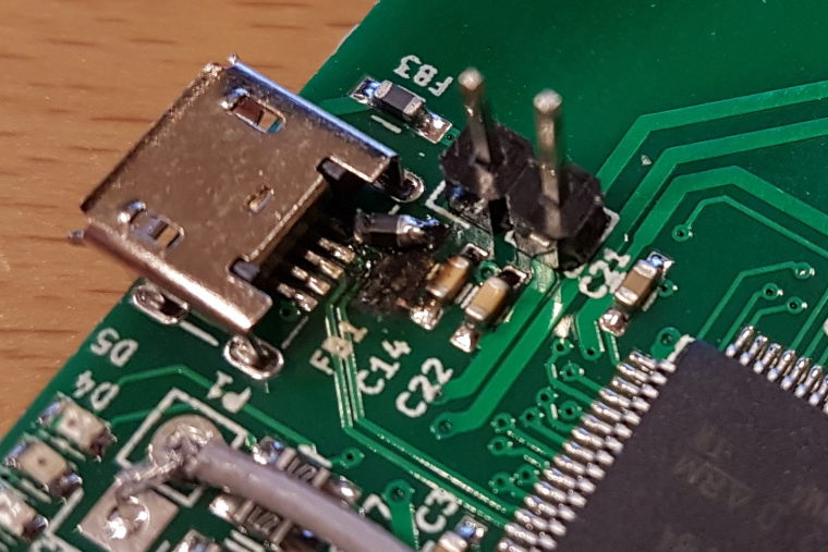
Received a new ferrite bead and soldered it to my device. The bead showed 0 ohm with a multimeter so I don't know if it is the real deal but it seems to work even if it is not pretty:
-
at DC it should be close to 0 ohm, but on higher frequencies it should act as a resistor.
btw. it seems like the old one had exploded?

-
@tbowmo said in
 Sensebender Gateway:
it seems like the old one had exploded?
That's what happens when you short Vraw to GND on the MYSX connector in one of those facepalm moments
 (we need an :facepalm emoji!).
-
I have a lot of problem with this gateway. First I think it was caused by network module but with serial sketch I have a lot of issues. After 2 or 3 days, gateway crash. If I remove some sensors reporting every 30 seconds it crash but later.
This morning, all leds are off on the board. After powering off and on it was ok.
I'im using RFM69 with Openhab2 as controller.
Is someone experience same issue ? I will fall back to my old Jeelink gateway (ATmega328 based).
-
I have used my sensebender gateway for more than a year now, only difference is that I use NRF24 radio.. Haven't had any hickups yet..
Which version of mysensors are you using?
-
I'm using version 2.1
-
Could you try the latest dev, and see how that behaves?
-
@tbowmo : with wich RFM69 driver ?
-
@Fabien legacy, unless you would reflash all your nodes with the new driver as well. (they are not compatible)
-
@tbowmo : Just flash my SBGW today with arduino 1.8.5, last boards.txt and dev branch of mysensors.
We will see if it's more stable. All my Node still in 2.1.1
-
Which driver to use on Ubuntu 16.04 ?
-
Hi, I'm trying to activate a sensebender gateway in OH2 on Ubuntu 16.04, however I'm having trouble setting up the serial port. Is there a how-to somewhere ? I suspect the serial port name is /dev/ttyACM0, but I'm not sure. How can I test ?
MySensors bundle is reported to be active, but there's no messages coming in. I set the log level for mysensors to DEBUG, but nothing on the log.
-
Here is my configuration file (mysensors.things)
Bridge mysensors:bridge-ser:gateway [ serialPort="/dev/ttyACM0", sendDelay=200 ]
{
humidity keuken_vochtigheid [ nodeId="3", childId="2", smartSleep=true ]
temperature keuken_temperatuur [ nodeId="3", childId="1", smartSleep=true ]
}I suppose ttyACM0 because of
stefaan@home:~$ dmesg |grep -i tty
[ 0.000000] console [tty0] enabled
[ 22.328631] 8086228A:00: ttyS4 at MMIO 0x81420000 (irq = 39, base_baud = 2764800) is a 16550A
[ 22.329059] 8086228A:01: ttyS5 at MMIO 0x8141e000 (irq = 40, base_baud = 2764800) is a 16550A
[ 23.106128] usb 1-4: FTDI USB Serial Device converter now attached to ttyUSB0
[362074.592743] cdc_acm 1-3:1.0: ttyACM0: USB ACM deviceThere seems to be a premissions problem om the port :
stefaan@home:~$ cat /dev/ttyACM0
cat: /dev/ttyACM0: Permission denieddoing 'sudo usermod -a -G dialout openhab' doesn't help
Anyone any ideas ?
-
ttyUSB0 is a (different) RFXcom device
-
@stefaanv I can only suggest scanning the ports. When I connected the Gateway to the Pi3 it came up with /dev/ttyS0 instead of the listed options, although I ultimately ended up changing to a Pro-Mini as the radio did not work, and connected direct to the GPIO the serial port it worked with.
-
it should pop up as ttyACM0 or ttyACM1 (if you have another usb device that enumerates first and gets ttyACM0)
I added the following to /etc/udev/rules.d/10-local.rules file:
ACTION=="add", ATTRS{idVendor}=="1209", ATTRS{idProduct}=="6949", SYMLINK+="ttyNRF24"What that does is to create a symlink from the real device to ttyNRF24, so regardless of what I add to my rPI, i always know that ttyNRF24 is for my gateway.
(and then I use /dev/ttyNRF24 for the serial port in my controller)
-
@tbowmo Definately ttyACM0
However, the setserial command returns information that doesn't look good : port0 and IRQ0. Does the board need a driver under Linux ?stefaan@home:~$ sudo setserial /dev/ttyACM0 /dev/ttyACM0, UART: unknown, Port: 0x0000, IRQ: 0, Flags: low_latency```
-
No, it doesn't need a driver..
I get the same for mine, if I use setserial:
thomas at jarvis in ~
>sudo setserial /dev/ttyNRF24
/dev/ttyNRF24, UART: unknown, Port: 0x0000, IRQ: 0, Flags: low_latency
thomas at jarvis in ~
>ll /dev/ttyNRF24
lrwxrwxrwx 1 root root 7 nov 11 13:39 /dev/ttyNRF24 -> ttyACM1
Btw. the permission problem.. You are logged in using your normal user (stefaan) and then you set permissions for openhab user? (see below). Have you tried setting the permissions for your user, and then cat /dev/ttyACM0?
@stefaanv said in
 Sensebender Gateway:
There seems to be a premissions problem om the port :
stefaan@home:~$ cat /dev/ttyACM0
cat: /dev/ttyACM0: Permission denieddoing 'sudo usermod -a -G dialout openhab' doesn't help
Anyone any ideas ?
-
@tbowmo OK, is working now after restarting the bundle in OH.
Must have been the permission problem after all.
Thanks for your help !!
-
When I try to compile SensebenderGW sketch with signing features, I receive a bunch of errors. What am I missing?
Arduino: 1.8.5 (Windows Store 1.8.10.0) (Windows 10), Board: "Sensebender Gateway"
In file included from C:\Users\rzylius\AppData\Local\Temp\arduino_modified_sketch_737033\SensebenderGatewaySerial.ino:88:0:
C:\Users\rzylius\Documents\Arduino\libraries\MySensors/drivers/ATSHA204/ATSHA204.cpp:6:16: error: redefinition of 'uint8_t device_pin'
static uint8_t device_pin;
^In file included from C:\Users\rzylius\Documents\Arduino\libraries\MySensors/MySensors.h:131:0,
from C:\Users\rzylius\AppData\Local\Temp\arduino_modified_sketch_737033\SensebenderGatewaySerial.ino:86:C:\Users\rzylius\Documents\Arduino\libraries\MySensors/drivers/ATSHA204/ATSHA204.cpp:6:16: error: 'uint8_t device_pin' previously declared here
static uint8_t device_pin;
^In file included from C:\Users\rzylius\AppData\Local\Temp\arduino_modified_sketch_737033\SensebenderGatewaySerial.ino:88:0:
C:\Users\rzylius\Documents\Arduino\libraries\MySensors/drivers/ATSHA204/ATSHA204.cpp: In function 'void swi_set_signal_pin(uint8_t)':
C:\Users\rzylius\Documents\Arduino\libraries\MySensors/drivers/ATSHA204/ATSHA204.cpp:24:13: error: redefinition of 'void swi_set_signal_pin(uint8_t)'
static void swi_set_signal_pin(uint8_t is_high)
^In file included from C:\Users\rzylius\Documents\Arduino\libraries\MySensors/MySensors.h:131:0,
from C:\Users\rzylius\AppData\Local\Temp\arduino_modified_sketch_737033\SensebenderGatewaySerial.ino:86:C:\Users\rzylius\Documents\Arduino\libraries\MySensors/drivers/ATSHA204/ATSHA204.cpp:24:13: error: 'void swi_set_signal_pin(uint8_t)' previously defined here
static void swi_set_signal_pin(uint8_t is_high)
^and the same type of errors reoccurs multiple times.
-
@rzylius I think you have an #include in the sketch for the atsha driver. Try to remove that #include from the sketch.
-
@Anticimex yes, when I delete #include atsha driver line, it compiles well. thanks.
-
@tbowmo After 2 month on the dev version, no more problem with the gateway. Perhaps it's time to made a new stable release ?
-
It's on the todo list..

-
I am looking for Gateway that will get me the results to MQTT but will support encryption + signing. That mean it should be easy to add new signatures (recompile/reflash) the module
I suppose if I use Sensebender with LAN module it will be a pain to do that
Is this doable if I use Orange zero as USB host for the Sensbender and let it act as serial gateway, then convert serial to mqtt with software on the Linux side? Also is it possible to reflash it easily this way? I do not want to rewire the hardware each time a add new node.
-
Is it over the air encryption / signing that you are aiming after? Then that is possible with the gateway, it has the ATSHA204 onboard for signing capabilities. And it also works with the W5100 module attached. The Gateway have 256Kb of flash onboard, so it has "enough" room for both network stack, and signing.
-
Are there performance limitations to be considered for mysensors and SensebenderGW specifically. Will the gateway handle the load of signed communications if rules will be firing messages to different sensors like 1-2-5-10 per second?
-
@rzylius if you use the atsha204a chip, it is the single wire interface that limits your throughput. I have no figures, so best is to just test how fast you can push messages through. Of course there is overhead in the OTA handshaking as well. That would probably be the bottleneck if you use software based signing.
-
I see in logs, that the whole process of signing and communicating to the node takes a bit more than one second. I do not know how to make a stress test properly, so I hoped that somebody else did it
 my question is if gateway will handle load by putting messages in some pipeline, or I should try to make sure that messages are fired with some spaces.
-
@rzylius The signing process is blocking, so it should not accept messages if a signed message exchange is in progress. But I have not tested that extensively with "aggressive" controllers.
-
im trying to program in arduino ide, installed board... bu when compiling it write mi an error 'The current selected board needs the core 'arduino:arduino' that is not installed.'
-
@mitja-blazinsek You'll need to install the Arduino SAMD board as well. I have just now updated the readme.
-
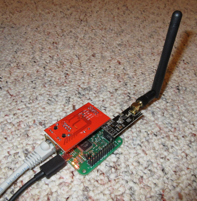
Just got my Sensebender GW and soldered it up. Adapted the serial sketch to Ethernet and it almost worked. Found some posts on this topic that helped me locate and fix my config error. Now all is well. Thanks! --edit-- added photo
-d
-
@dklinkman said in
 Sensebender Gateway:
Sensebender
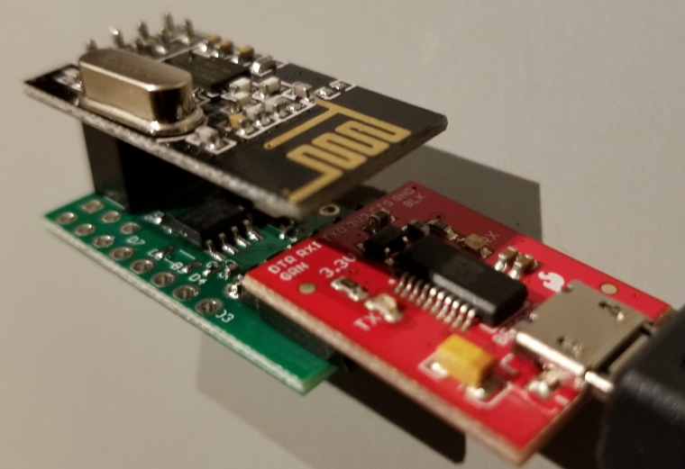
And I got a Sensebender Micro soldered up and running also!! Just temp and humid so far. Too cool
--edit-- picture
-
This post is deleted!
-
Is it possible to use the sensebender board as MQTT gateway? Not Ethernet?
-
Yes it is! I use I'm using it as a MQTT gateway for some time
-
First: Great work! My GW is working very well!
I wanted to know for what I can use the SD-Card.
My idea is to fetch the logs in the serial and write them to the SD-Card.
But I don't know where. Is there a point in the mySensors core where I can fetch all logs?
-
Forgive me if this isn't the right place to ask; but as a beginner, where do I start? How can I order this thing, or any other stuff from OpenHardware.io ? I see so many design files, I'm not sure what to do with them. Soldering the thing I can probably manage, but is there a guide available how to order the PCB, and maybe the parts as well?
-
@rolandow said in
 Sensebender Gateway:
Forgive me if this isn't the right place to ask; but as a beginner, where do I start? How can I order this thing, or any other stuff from OpenHardware.io ? I see so many design files, I'm not sure what to do with them. Soldering the thing I can probably manage, but is there a guide available how to order the PCB, and maybe the parts as well?
Sesnebender GW can be ordered from Itead:
https://www.itead.cc/mysensors-gateway.html
Other openhardware.io projects maybe ordered either (1) directly from a link; pcb only (2) you can download eagle files and upload them to pcb manufactures like oshpark.com (3) you can purchase the final product. So a generic answer to your question is it depends

I do not think there is a guide here, but if you go to oshpark.com there is a guide how to order a pcb. Parts (BOM) can be ordered from Aliexpress, eBay or more reputable supplies like digi-key or mouser
-
Hi!
I'm trying to use sensebender GW as ethernet gateway. I loaded the stock W5100 sketch compiled with samd 1.6.21 defs but it didn't worked. I have been trying out different things and realized that it works with 1.6.12 defs. Now it's working but I'm stuck with an old version. Anyone with the same problem? Maybe I'm missing something?
Also I found out ethernet library in 1.0.5 defs is outdated. I have been trying to use stock one (v2.0) without success. Anyone has tried?
Thanks.
-
hi
when i try compile sketch only with change radio to rfm69hw i have this:
Arduino:1.8.9 (Windows 10), Płytka:"Arduino/Genuino Mega or Mega 2560, ATmega2560 (Mega 2560)"SensebenderGatewaySerial:95:26: error: 'LED_BLUE' was not declared in this scope
static uint8_t leds[] = {LED_BLUE, LED_RED, LED_GREEN, LED_YELLOW, LED_ORANGE};
^SensebenderGatewaySerial:95:36: error: 'LED_RED' was not declared in this scope
static uint8_t leds[] = {LED_BLUE, LED_RED, LED_GREEN, LED_YELLOW, LED_ORANGE};
^SensebenderGatewaySerial:95:45: error: 'LED_GREEN' was not declared in this scope
static uint8_t leds[] = {LED_BLUE, LED_RED, LED_GREEN, LED_YELLOW, LED_ORANGE};
^SensebenderGatewaySerial:95:56: error: 'LED_YELLOW' was not declared in this scope
static uint8_t leds[] = {LED_BLUE, LED_RED, LED_GREEN, LED_YELLOW, LED_ORANGE};
^SensebenderGatewaySerial:95:68: error: 'LED_ORANGE' was not declared in this scope
static uint8_t leds[] = {LED_BLUE, LED_RED, LED_GREEN, LED_YELLOW, LED_ORANGE};
^C:\Users\Piotrek\Desktop\SensebenderGatewaySerial-sketch\SensebenderGatewaySerial\SensebenderGatewaySerial.ino: In function 'void preHwInit()':
SensebenderGatewaySerial:116:10: error: 'MY_SWC1' was not declared in this scope
pinMode(MY_SWC1, INPUT_PULLUP);
^SensebenderGatewaySerial:117:10: error: 'MY_SWC2' was not declared in this scope
pinMode(MY_SWC2, INPUT_PULLUP);
^SensebenderGatewaySerial:130:17: error: 'LED_BLUE' was not declared in this scope
digitalWrite(LED_BLUE, led_state);

             ^
SensebenderGatewaySerial:145:16: error: 'LED_GREEN' was not declared in this scope
digitalWrite(LED_GREEN, HIGH);
^SensebenderGatewaySerial:149:16: error: 'LED_YELLOW' was not declared in this scope
digitalWrite(LED_YELLOW, HIGH);
^SensebenderGatewaySerial:154:16: error: 'LED_ORANGE' was not declared in this scope
digitalWrite(LED_ORANGE, HIGH);
^SensebenderGatewaySerial:167:17: error: 'LED_RED' was not declared in this scope
digitalWrite(LED_RED, HIGH);

             ^
C:\Users\Piotrek\Desktop\SensebenderGatewaySerial-sketch\SensebenderGatewaySerial\SensebenderGatewaySerial.ino: In function 'bool testSDCard()':
SensebenderGatewaySerial:219:33: error: 'MY_SDCARD_CS' was not declared in this scope
if (!card.init(SPI_HALF_SPEED, MY_SDCARD_CS)) {
^C:\Users\Piotrek\Desktop\SensebenderGatewaySerial-sketch\SensebenderGatewaySerial\SensebenderGatewaySerial.ino: In function 'bool testEEProm()':
SensebenderGatewaySerial:249:2: error: 'SerialUSB' was not declared in this scope
SerialUSB.print(" -> EEPROM ");
^
C:\Users\Piotrek\Desktop\SensebenderGatewaySerial-sketch\SensebenderGatewaySerial\SensebenderGatewaySerial.ino: In function 'bool testAnalog()':
SensebenderGatewaySerial:267:30: error: 'MY_BAT_DETECT' was not declared in this scope
int bat_detect = analogRead(MY_BAT_DETECT);
^exit status 1
'LED_BLUE' was not declared in this scopeWhat is error ? please help me
-
I also can not install board in Arduino IDE 1.8.9
-
-
@pepson said in
 Sensebender Gateway:
hi
when i try compile sketch only with change radio to rfm69hw i have this:
Arduino:1.8.9 (Windows 10), Płytka:"Arduino/Genuino Mega or Mega 2560, ATmega2560 (Mega 2560)"SensebenderGatewaySerial:95:26: error: 'LED_BLUE' was not declared in this scope
You cannot use the SensebenderGatewaySerial sketch on an Atmega2560. The SensbenderGatewaySerial sketch is for the SAMD board called Sensebender Gateway.
If you have the real Sensebender Gateway you should use this one
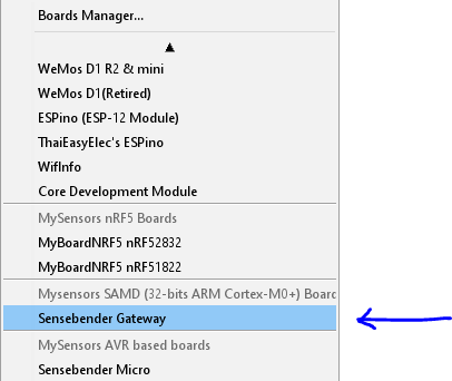
-
@magpern
But get this board to Arduino IDE?
-
@pepson said in
 Sensebender Gateway:
@magpern
But get this board to Arduino IDE?Boards / Boards manager...
search for sensebender
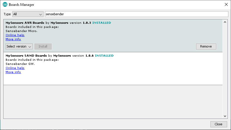
You might have to
File / Preferences / Additional Board manager URLs
add
https://raw.githubusercontent.com/mysensors/ArduinoBoards/master/package_mysensors.org_index.json
-
Hi
I compiled and write to gateway this programmm. Then i connected it to my RPI with Hassio (Home Assistant). In logs on home assistant still show me info: Gateway /dev/serial/by-id/usb-MySensors.org_Sensebender_GW_6A153443514D355934202020FF10182D-if00 not ready after 15.0 secs so continuing with setupbut after run Home Assistant gateway works ok. I send info mto developer Home Assistant ans she not see any bugs....
How i can resolved this problem ?
-
And please help me how i can compile it as gateway Ethernet with module W5100.
Only add to sketch:
// Enable gateway ethernet module type
#define MY_GATEWAY_W5100// Enable to UDP
//#define MY_USE_UDP//#define MY_IP_ADDRESS 192,168,3,160 // wpisz adres ip bramki
// Renewal period if using DHCP
//#define MY_IP_RENEWAL_INTERVAL 60000
// The port to keep open on node server mode / or port to contact in client mode
#define MY_PORT 5003 //wpisz numer portu bramki// Controller ip address. Enables client mode (default is "server" mode).
// Also enable this if MY_USE_UDP is used and you want sensor data sent somewhere.
//#define MY_CONTROLLER_IP_ADDRESS 192, 168, 178, 254// The MAC address can be anything you want but should be unique on your network.
// Newer boards have a MAC address printed on the underside of the PCB, which you can (optionally) use.
// Note that most of the Ardunio examples use "DEAD BEEF FEED" for the MAC address.
#define MY_MAC_ADDRESS 0xDC, 0xAE, 0xB2, 0x3F, 0xFF, 0xDC???
-
When try compilation with this W5100 i get error:
Opcje projektu zmienione, przeładuj całość
In file included from C:\Users\Piotrek\Documents\Arduino\libraries\MySensors/MySensors.h:208:0,from C:\Users\Piotrek\Desktop\SensebenderGatewayETHERNET\SensebenderGatewayETHERNET.ino:111:C:\Users\Piotrek\Documents\Arduino\libraries\MySensors/core/MyGatewayTransportEthernet.cpp:74:1: error: 'EthernetServer' does not name a type
EthernetServer _ethernetServer(_ethernetGatewayPort);
^~~~~~~~~~~~~~
C:\Users\Piotrek\Documents\Arduino\libraries\MySensors/core/MyGatewayTransportEthernet.cpp:89:8: error: 'EthernetClient' does not name a type
static EthernetClient client = EthernetClient();
^~~~~~~~~~~~~~C:\Users\Piotrek\Documents\Arduino\libraries\MySensors/core/MyGatewayTransportEthernet.cpp: In function 'bool gatewayTransportInit()':
C:\Users\Piotrek\Documents\Arduino\libraries\MySensors/core/MyGatewayTransportEthernet.cpp:149:7: error: 'Ethernet' was not declared in this scope
if (!Ethernet.begin(_ethernetGatewayMAC)) {
^~~~~~~~C:\Users\Piotrek\Documents\Arduino\libraries\MySensors/core/MyGatewayTransportEthernet.cpp:149:7: note: suggested alternative: '_ethernetMsg'
if (!Ethernet.begin(_ethernetGatewayMAC)) {
   ^~~~~~~~

   _ethernetMsg
In file included from C:\Users\Piotrek\Documents\Arduino\libraries\MySensors/MySensors.h:49:0,
from C:\Users\Piotrek\Desktop\SensebenderGatewayETHERNET\SensebenderGatewayETHERNET.ino:111:C:\Users\Piotrek\Documents\Arduino\libraries\MySensors/core/MyGatewayTransportEthernet.cpp:156:16: error: 'Ethernet' was not declared in this scope
            Ethernet.localIP()[0],

            ^
C:\Users\Piotrek\Documents\Arduino\libraries\MySensors/MyConfig.h:1815:48: note: in definition of macro 'DEBUG_OUTPUT'
#define DEBUG_OUTPUT(x,...) hwDebugPrint(x, ##VA_ARGS) //!< debug
^~~~~~~~~~~C:\Users\Piotrek\Documents\Arduino\libraries\MySensors/core/MyGatewayTransportEthernet.cpp:155:2: note: in expansion of macro 'GATEWAY_DEBUG'
GATEWAY_DEBUG(PSTR("GWT:TIN:IP=%" PRIu8 ".%" PRIu8 ".%" PRIu8 ".%" PRIu8 "\n"),
^~~~~~~~~~~~~
C:\Users\Piotrek\Documents\Arduino\libraries\MySensors/core/MyGatewayTransportEthernet.cpp:156:16: note: suggested alternative: '_ethernetMsg'
            Ethernet.localIP()[0],

            ^
C:\Users\Piotrek\Documents\Arduino\libraries\MySensors/MyConfig.h:1815:48: note: in definition of macro 'DEBUG_OUTPUT'
#define DEBUG_OUTPUT(x,...) hwDebugPrint(x, ##VA_ARGS) //!< debug
^~~~~~~~~~~C:\Users\Piotrek\Documents\Arduino\libraries\MySensors/core/MyGatewayTransportEthernet.cpp:155:2: note: in expansion of macro 'GATEWAY_DEBUG'
GATEWAY_DEBUG(PSTR("GWT:TIN:IP=%" PRIu8 ".%" PRIu8 ".%" PRIu8 ".%" PRIu8 "\n"),
^~~~~~~~~~~~~
In file included from C:\Users\Piotrek\Documents\Arduino\libraries\MySensors/MySensors.h:208:0,
from C:\Users\Piotrek\Desktop\SensebenderGatewayETHERNET\SensebenderGatewayETHERNET.ino:111:C:\Users\Piotrek\Documents\Arduino\libraries\MySensors/core/MyGatewayTransportEthernet.cpp:189:2: error: '_ethernetServer' was not declared in this scope
_ethernetServer.begin();
^~~~~~~~~~~~~~~
C:\Users\Piotrek\Documents\Arduino\libraries\MySensors/core/MyGatewayTransportEthernet.cpp:189:2: note: suggested alternative: '_ethernetMsg'
_ethernetServer.begin();
       ^~~~~~~~~~~~~~~

       _ethernetMsg
C:\Users\Piotrek\Documents\Arduino\libraries\MySensors/core/MyGatewayTransportEthernet.cpp: In function 'bool gatewayTransportSend(MyMessage&)':
C:\Users\Piotrek\Documents\Arduino\libraries\MySensors/core/MyGatewayTransportEthernet.cpp:246:11: error: '_ethernetServer' was not declared in this scope
nbytes = _ethernetServer.write(_ethernetMsg);
^~~~~~~~~~~~~~~C:\Users\Piotrek\Documents\Arduino\libraries\MySensors/core/MyGatewayTransportEthernet.cpp:246:11: note: suggested alternative: '_ethernetMsg'
nbytes = _ethernetServer.write(_ethernetMsg);
^~~~~~~~~~~~~~~ _ethernetMsgC:\Users\Piotrek\Documents\Arduino\libraries\MySensors/core/MyGatewayTransportEthernet.cpp: In function 'bool _readFromClient()':
C:\Users\Piotrek\Documents\Arduino\libraries\MySensors/core/MyGatewayTransportEthernet.cpp:289:9: error: 'client' was not declared in this scope
while (client.connected() && client.available()) {
^~~~~~C:\Users\Piotrek\Documents\Arduino\libraries\MySensors/core/MyGatewayTransportEthernet.cpp:289:9: note: suggested alternative: 'Print'
while (client.connected() && client.available()) {
     ^~~~~~

     Print
C:\Users\Piotrek\Documents\Arduino\libraries\MySensors/core/MyGatewayTransportEthernet.cpp: In function 'bool gatewayTransportAvailable()':
C:\Users\Piotrek\Documents\Arduino\libraries\MySensors/core/MyGatewayTransportEthernet.cpp:409:2: error: 'EthernetClient' was not declared in this scope
EthernetClient newclient = _ethernetServer.available();
^~~~~~~~~~~~~~
C:\Users\Piotrek\Documents\Arduino\libraries\MySensors/core/MyGatewayTransportEthernet.cpp:411:6: error: 'newclient' was not declared in this scope
if (newclient) {
^~~~~~~~~C:\Users\Piotrek\Documents\Arduino\libraries\MySensors/core/MyGatewayTransportEthernet.cpp:412:7: error: 'client' was not declared in this scope
if (client != newclient) {
^~~~~~C:\Users\Piotrek\Documents\Arduino\libraries\MySensors/core/MyGatewayTransportEthernet.cpp:412:7: note: suggested alternative: 'Print'
if (client != newclient) {
   ^~~~~~

   Print
C:\Users\Piotrek\Documents\Arduino\libraries\MySensors/core/MyGatewayTransportEthernet.cpp:422:6: error: 'client' was not declared in this scope
if (client) {
^~~~~~C:\Users\Piotrek\Documents\Arduino\libraries\MySensors/core/MyGatewayTransportEthernet.cpp:422:6: note: suggested alternative: 'Print'
if (client) {
  ^~~~~~

  Print
C:\Users\Piotrek\Documents\Arduino\libraries\MySensors/core/MyGatewayTransportEthernet.cpp: In function 'void gatewayTransportRenewIP()':
C:\Users\Piotrek\Documents\Arduino\libraries\MySensors/core/MyGatewayTransportEthernet.cpp:463:6: error: 'Ethernet' was not declared in this scope
if (Ethernet.maintain() & ~(0x06)) {
^~~~~~~~C:\Users\Piotrek\Documents\Arduino\libraries\MySensors/core/MyGatewayTransportEthernet.cpp:463:6: note: suggested alternative: '_ethernetMsg'
if (Ethernet.maintain() & ~(0x06)) {
  ^~~~~~~~

  _ethernetMsg
exit status 1
Błąd kompilacji dla płytki Sensebender Gateway.What is a problem ?
-
please help me....
-
Hi
Can anybody help me how compile sketch to this gateway to work as Ethernet Gateway...
When i try compile i get the error:
https://pastebin.com/BSQGsCgiand my sketch looks like:
https://pastebin.com/R3vG076i
-
-
@tekka
No.... thanks i fixed it....:)
-
I just got my Sensebender Gateway and loaded the Sensebender Gateway Serial sketch. When I use the MYSController I get those wired infos...
Currently there is no other Snesor runing just the Sensebender Gateway with an RF24. Why does it see a new child and what are all thos "hu;hu;hu" errors?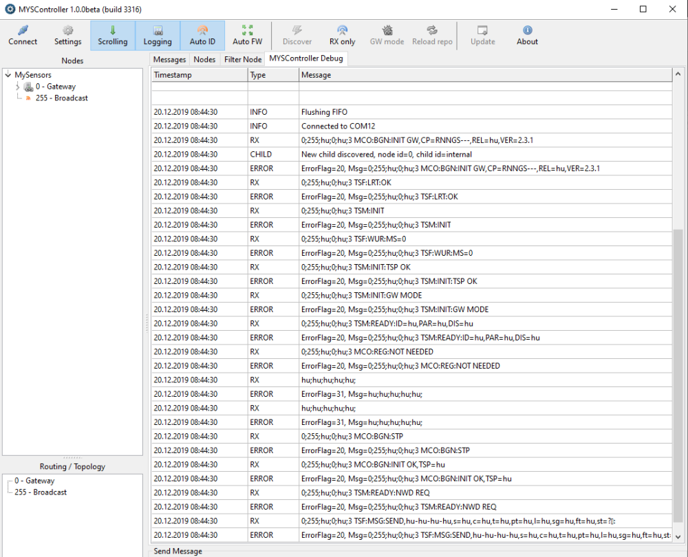
-
Ok solved it by adding:
#undef PRId8
#undef PRIi8
#undef PRIo8
#undef PRIu8
#undef PRIx8
#undef PRIX8
#undef PRIdLEAST8
#undef PRIiLEAST8
#undef PRIoLEAST8
#undef PRIuLEAST8
#undef PRIxLEAST8
#undef PRIXLEAST8
#undef PRIdFAST8
#undef PRIiFAST8
#undef PRIoFAST8
#undef PRIuFAST8
#undef PRIxFAST8
#undef PRIXFAST8
#define PRId8    "d"
#define PRIi8   "i"
#define PRIo8   "o"
#define PRIu8   "u"
#define PRIx8   "x"
#define PRIX8   "X"
#define PRIdLEAST8  "d"
#define PRIiLEAST8  "i"
#define PRIoLEAST8  "o"
#define PRIuLEAST8  "u"
#define PRIxLEAST8  "x"
#define PRIXLEAST8  "X"
#define PRIdFAST8 "d"
#define PRIiFAST8 "i"
#define PRIoFAST8 "o"
#define PRIuFAST8 "u"
#define PRIxFAST8 "x"
#define PRIXFAST8 "X"
-
Hello,
I have a similar issue with Sensebender Ethernet MQTT Gateway and MYSController. Can only connect to the gateway by serial from MYSController. The set-up is working correctly as best I can tell, and has several different MySensors in use. Has been working for a number of years. Only just discovered the MYSController software.
So the Controller only shows data in the MYSController Debug tab. Nothing in any of the others. NOTE in the screen grab below the Controller at 192.168.1.96 is not connected, there is no difference when it is other than the Gateway error (!GWT:RMQ:FAIL) is not shown. Anyone with any ides for me to pursue? Thanks.
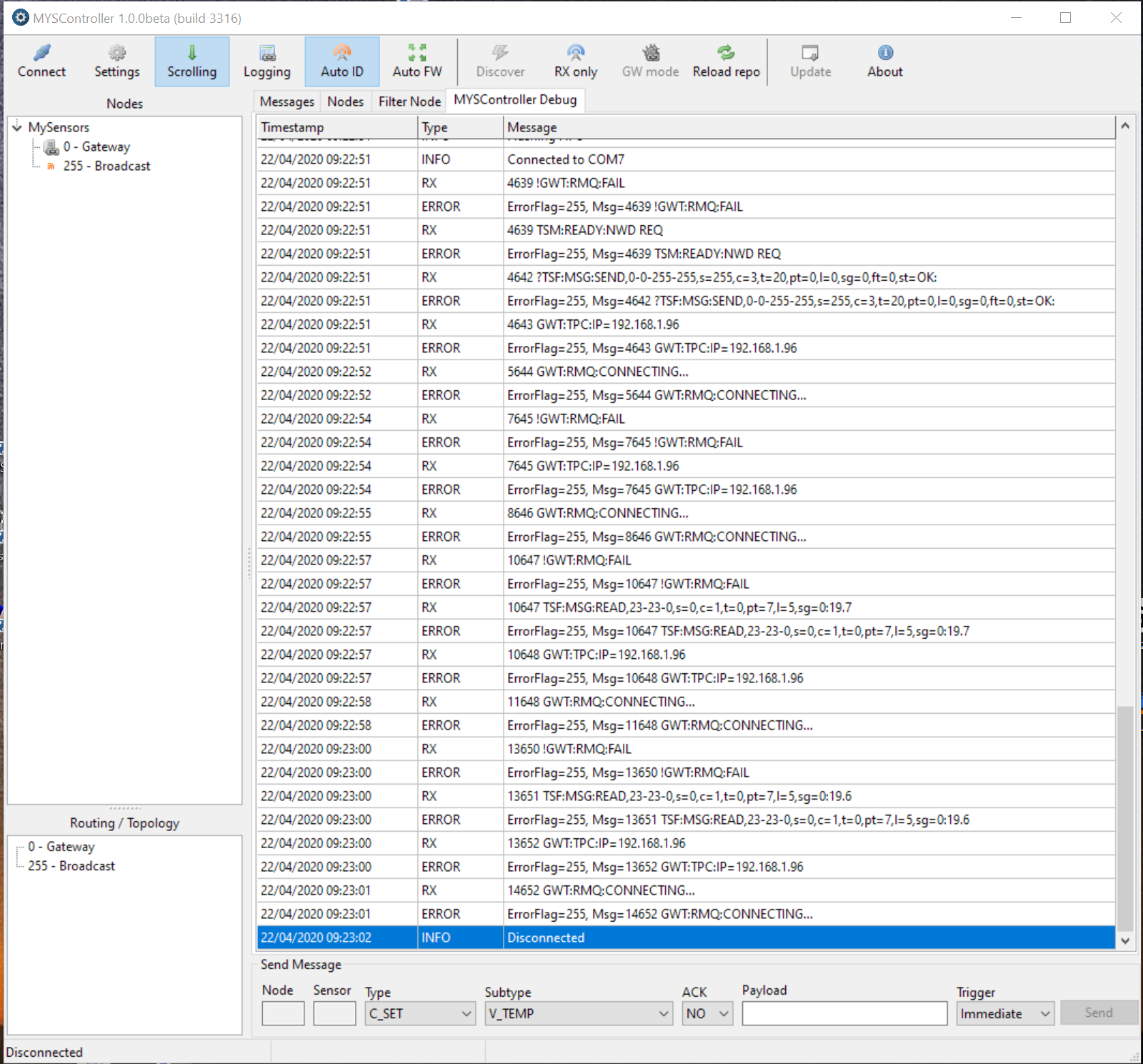
-
As previously noted, Sensebender Gateway sketch from 2.3.2 with MySensors SAMD Boards 1.0.6 does not compile with Arduino SAMD Boards 1.8.9. Rolling back to Arduino SAMD Boards 1.8.8 or earlier version works.
-
Does anyone have an idea about the sensebender gateway board not being recognised in windows 11? A new driver maybe or any other clues ?
-
Unfortunately I do not have any hardware compatible with win11, so can't test myself.. But if I remember right it should turn up as a generic cdc device..
Is there any info in the windows device manager?
-
Nothing new appears in device manager or the usual ding.
-
@Yoshu Does the same device work on another machine, running win10 / linux?
-
I have not had the opportunity to try another machine yet. unfortunately I had only just given into the windows 11 upgrade messages days before deciding to set up my gateway.
-
@Yoshu you could boot linux off a usb, and check there..
-
Sensebender ethernet gateway success with help.
Was unable to connect sensebender to Windows 11.
Using a suggesetions and assistance by tbowmo
(you could boot linux off a usb, and check there..)I used an old rasberry pi with Arduino ide to connect and load the sketch, loaded
Mysensors SAMD and Arduino SAMD board profiles, inital compile errors (clinent.h) but recified this with the help of comments by
bjornhallberg (Sensebender Gateway sketch from 2.3.2 with MySensors SAMD Boards 1.0.6 does not compile with Arduino SAMD Boards 1.8.9. Rolling back to Arduino SAMD Boards 1.8.8).Used the standard ethernet gateway sketch that I am using with my unsecured nano ethernet gateway. Only changed the ip address and #define MY_RF24_CHANNEL to another channel for this second gateway.
I have not setup signing yet, but that is my intention for my sensebender gateway now the basics are working.
-
I'll update the PDF once I get to my own computer (which should be Sunday evening)