πŸ’¬ Button size radionode with sensors swarm extension


  • Contest Winner

    @bjornhallberg I do not know exactly, but I don't think there should be any fees. Try to find out tomorrow.


  • @Koresh I got one of boards and would like to add Si1132-A10-GMR. What else I need to add? C8?
    Why are you not using this sensor on your board?


  • Contest Winner

    @alexsh1 yes, you should solder the sensor and the bypass capacitor. I have a lot of si1132 sensors, but I can't find the correct library. Almost promo videos of commertial sensors based on the si1132 shows incorrect data ))) It shows correct UV and IR level, but incorrect visible light value. So I decided to not solder this sensor yet.


  • @Koresh I would only use it for UV so this is good for me.

    No need to use a lib:

    // Distributed with a free-will license.
    // Use it any way you want, profit or free, provided it fits in the licenses of its associated works.
    // SI1132
    // This code is designed to work with the SI1132_I2CS I2C Mini Module available from ControlEverything.com.
    // https://www.controleverything.com/content/Light?sku=SI1132_I2CS#tabs-0-product_tabset-2
    
    #include<Wire.h>
    
    // SI1132 I2C address is 0x60(96)
    #define Addr 0x60
    
    int response = 0;
    void setup()
    {
      // Initialise I2C communication as MASTER
      Wire.begin();
      // Initialise Serial Communication, Baud rate = 9600
      Serial.begin(9600);
    
      // Enable UVindex measurement coefficients
      // Start I2C Transmission
      Wire.beginTransmission(Addr);
      // Select COFF-1 register
      Wire.write(0x13);
      // Default value
      Wire.write(0x29);
      // Stop I2C Transmission
      Wire.endTransmission();
    
      // Start I2C Transmission
      Wire.beginTransmission(Addr);
      // Select COFF-2 register
      Wire.write(0x14);
      // Default value
      Wire.write(0x89);
      // Stop I2C Transmission
      Wire.endTransmission();
    
      // Start I2C Transmission
      Wire.beginTransmission(Addr);
      // Select COFF-3 register
      Wire.write(0x15);
      // Default value
      Wire.write(0x02);
      // Stop I2C Transmission
      Wire.endTransmission();
    
      // Start I2C Transmission
      Wire.beginTransmission(Addr);
      // Select COFF-4 register
      Wire.write(0x16);
      // Default value
      Wire.write(0x00);
      // Stop I2C Transmission
      Wire.endTransmission();
    
    
      // Start I2C Transmission
      Wire.beginTransmission(Addr);
      // Select PARAM_WR register
      Wire.write(0x17);
      // Enable uv, Visible, IR
      Wire.write(0xF0);
      // Stop I2C Transmission
      Wire.endTransmission();
    
    
      // Start I2C Transmission
      Wire.beginTransmission(Addr);
      // Select command register
      Wire.write(0x18);
      // Select CHLIST register in RAM
      Wire.write(0x01 | 0xA0);
      // Stop I2C Transmission
      Wire.endTransmission();
      delay(10);
    
      // Start I2C Transmission
      Wire.beginTransmission(Addr);
      // Select PARAM_RD register
      Wire.write(0x2E);
      // Stop I2C Transmission
      Wire.endTransmission();
    
      // Request 1 byte of data
      Wire.requestFrom(Addr, 1);
      // Read 1 byte of data
      response = Wire.read();
    
      // Start I2C Transmission
      Wire.beginTransmission(Addr);
      // Select HW_KEY register
      Wire.write(0x07);
      // Default value
      Wire.write(0x17);
      // Stop I2C Transmission
      Wire.endTransmission();
    
      // Start I2C Transmission
      Wire.beginTransmission(Addr);
      // Select PARAM_WR register
      Wire.write(0x17);
      // Small IR photodiode
      Wire.write(0x00);
      // Stop I2C Transmission
      Wire.endTransmission();
    
      // Start I2C Transmission
      Wire.beginTransmission(Addr);
      // Select COMMAND register
      Wire.write(0x18);
      // Select ALS_IR_ADCMUX register in RAM
      Wire.write(0x0E | 0xA0);
      // Stop I2C Transmission
      Wire.endTransmission();
      delay(10);
    
      // Start I2C Transmission
      Wire.beginTransmission(Addr);
      // Select PARAM_RD register
      Wire.write(0x2E);
      // Stop I2C Transmission
      Wire.endTransmission();
    
      // Request 1 byte of data
      Wire.requestFrom(Addr, 1);
      // Read 1 byte of data
      response = Wire.read();
    
      // Start I2C Transmission
      Wire.beginTransmission(Addr);
      // Select PARAM_WR register
      Wire.write(0x17);
      // Set ADC Clock divided / 1
      Wire.write(0x00);
      // Stop I2C Transmission
      Wire.endTransmission();
    
      // Start I2C Transmission
      Wire.beginTransmission(Addr);
      // Select COMMAND register
      Wire.write(0x18);
      // Select ALS_IR_ADC_GAIN register in RAM
      Wire.write(0x1E | 0xA0);
      // Stop I2C Transmission
      Wire.endTransmission();
      delay(10);
    
      // Start I2C Transmission
      Wire.beginTransmission(Addr);
      // Select PARAM_RD register
      Wire.write(0x2E);
      // Stop I2C Transmission
      Wire.endTransmission();
    
      // Request 1 byte of data
      Wire.requestFrom(Addr, 1);
      // Read 1 byte of data
      response = Wire.read();
    
      // Start I2C Transmission
      Wire.beginTransmission(Addr);
      // Select PARAM_WR register
      Wire.write(0x17);
      // Set 511 ADC Clock
      Wire.write(0x70);
      // Stop I2C Transmission
      Wire.endTransmission();
    
      // Start I2C Transmission
      Wire.beginTransmission(Addr);
      // Select COMMAND register
      Wire.write(0x18);
      // Select ALS_IR_ADC_COUNTER register in RAM
      Wire.write(0x1D | 0xA0);
      // Stop I2C Transmission
      Wire.endTransmission();
      delay(10);
    
      // Start I2C Transmission
      Wire.beginTransmission(Addr);
      // Select PARAM_RD register
      Wire.write(0x2E);
      // Stop I2C Transmission
      Wire.endTransmission();
    
      // Request 1 byte of data
      Wire.requestFrom(Addr, 1);
      // Read 1 byte of data
      response = Wire.read();
    
      // Start I2C Transmission
      Wire.beginTransmission(Addr);
      // Select PARAM_WR register
      Wire.write(0x17);
      // Set ADC Clock divided / 1
      Wire.write(0x00);
      // Stop I2C Transmission
      Wire.endTransmission();
    
      // Start I2C Transmission
      Wire.beginTransmission(Addr);
      // Select COMMAND register
      Wire.write(0x18);
     // Select ALS_VIS_ADC_GAIN register in RAM
      Wire.write(0x11 | 0xA0);
      // Stop I2C Transmission
      Wire.endTransmission();
      delay(10);
    
      // Start I2C Transmission
      Wire.beginTransmission(Addr);
      // Select PARAM_RD register
      Wire.write(0x2E);
      // Stop I2C Transmission
      Wire.endTransmission();
    
      // Request 1 byte of data
      Wire.requestFrom(Addr, 1);
      // Read 1 byte of data
      response = Wire.read();
    
      // Start I2C Transmission
      Wire.beginTransmission(Addr);
      // Select PARAM_WR register
      Wire.write(0x17);
      // High Signal Range
      Wire.write(0x20);
      // Stop I2C Transmission
      Wire.endTransmission();
    
      // Start I2C Transmission
      Wire.beginTransmission(Addr);
      // Select COMMAND register
      Wire.write(0x18);
      // Select ALS_IR_ADC_MISC register in RAM
      Wire.write(0x1F | 0xA0);
      // Stop I2C Transmission
      Wire.endTransmission();
      delay(10);
    
      // Start I2C Transmission
      Wire.beginTransmission(Addr);
      // Select PARAM_RD register
      Wire.write(0x2E);
      // Stop I2C Transmission
      Wire.endTransmission();
    
      // Request 1 byte of data
      Wire.requestFrom(Addr, 1);
      // Read 1 byte of data
      response = Wire.read();
    
      // Start I2C Transmission
      Wire.beginTransmission(Addr);
      // Select PARAM_WR register
      Wire.write(0x17);
      // Set 511 ADC Clock
      Wire.write(0x70);
      // Stop I2C Transmission
      Wire.endTransmission();
    
      // Start I2C Transmission
      Wire.beginTransmission(Addr);
      // Select COMMAND register
      Wire.write(0x18);
      // Select ALS_VIS_ADC_COUNTER register in RAM
      Wire.write(0x10 | 0xA0);
      // Stop I2C Transmission
      Wire.endTransmission();
      delay(10);
    
      // Start I2C Transmission
      Wire.beginTransmission(Addr);
      // Select PARAM_RD register
      Wire.write(0x2E);
      // Stop I2C Transmission
      Wire.endTransmission();
    
      // Request 1 byte of data
      Wire.requestFrom(Addr, 1);
      // Read 1 byte of data
      response = Wire.read();
    
      // Start I2C Transmission
      Wire.beginTransmission(Addr);
      // Select PARAM_WR register
      Wire.write(0x17);
      // High Signal Range
      Wire.write(0x20);
      // Stop I2C Transmission
      Wire.endTransmission();
    
      // Start I2C Transmission
      Wire.beginTransmission(Addr);
      // Select COMMAND register
      Wire.write(0x18);
      // Select ALS_VIS_ADC_MISC register in RAM
      Wire.write(0x12 | 0xA0);
      // Stop I2C Transmission
      Wire.endTransmission();
      delay(10);
    
      // Start I2C Transmission
      Wire.beginTransmission(Addr);
      // Select PARAM_RD register
      Wire.write(0x2E);
      // Stop I2C Transmission
      Wire.endTransmission();
    
      // Request 1 byte of data
      Wire.requestFrom(Addr, 1);
      // Read 1 byte of data
      response = Wire.read();
      delay(300);
    }
    void loop()
    {
      unsigned int data[4];
    
      // Start I2C Transmission
      Wire.beginTransmission(Addr);
      // Select COMMAND register
      Wire.write(0x18);
      // Start ALS conversion
      Wire.write(0x0E);
      // Stop I2C Transmission
      Wire.endTransmission();
      delay(500);
    
      // Start I2C Transmission
      Wire.beginTransmission(Addr);
      // Select data register
      Wire.write(0x22);
      // Stop I2C Transmission
      Wire.endTransmission();
      
      // Request 4 byte of data
      Wire.requestFrom(Addr, 4);
    
      // Read 4 bytes of data
      // visible lsb, visible msb, ir lsb, ir msb
      if (Wire.available() == 4)
      {
        data[0] = Wire.read();
        data[1] = Wire.read();
        data[2] = Wire.read();
        data[3] = Wire.read();
      }
    
      float visible = (data[1] * 256.0 + data[0]);
      float ir = (data[3] * 256 + data[2]);
    
      // Start I2C Transmission
      Wire.beginTransmission(Addr);
      // Select data register
      Wire.write(0x2C);
      // Stop I2C Transmission
      Wire.endTransmission();
      
      // Request 2 bytes of data
      Wire.requestFrom(Addr, 2);
    
      // Read 2 bytes of data
      // uv lsb, uv msb
      if (Wire.available() == 2)
      {
        data[0] = Wire.read();
        data[1] = Wire.read();
      }
      // Convert the data
      float uv = (data[1] * 256 + data[0]);
    
      // Output data to screen
      Serial.print("Visible Light of Source : ");
      Serial.print(visible);
      Serial.println(" lux");
      Serial.print("IR Of Source : ");
      Serial.print(ir);
      Serial.println(" lux");
      Serial.print("UV Of the Source : ");
      Serial.print(uv);
      Serial.println(" lux");
      delay(500);
    }


  • @Koresh BTW, Found this library - working fine for my needs

    https://github.com/hardkernel/WEATHER-BOARD/tree/master/libraries/ODROID_Si1132

    I am using this sensor purely for UV Index.

    PS Got your sensor. Soldered it to the mote. Works just fine


  • @Koresh I can see Si1132 visible light is twice more than BH1750.
    Not sure what's wrong, but as you said it reports incorrect value.

    UV Index is in line with VEML6070


  • The sensor looks more complicated that I thought:

    2.2. Ambient Light
    The Si1132 has photodiodes capable of measuring both vi
    sible and infrared light. Howe
    ver, the visible photodiode
    is also influenced by infrared light. The measurement of illuminance require
    s the same spectral response as the
    human eye. If an accurate lux measurement is desired, the
    extra IR response of the vi
    sible-light photodiode must
    be compensated. Therefore, to allow the host to make corrections to the infrared light’s influence, the Si1132
    reports the infrared light measurement on a separate channel. The separate visible and IR photodiodes lend
    themselves to a variety of algorithmic solutions. The
    host can then take these two measurements and run an
    algorithm to derive an equivalent lux level as perceive
    d by a human eye. Having
    the IR correction algorithm
    running in the host a
    llows for the most flexibility in adjusting for system-dependent
    variables. For example, if the
    glass used in the system blocks visibl
    e light more than infrared light, the
    IR correction needs to be adjusted.

    I will have to spend more time to understand how to extract the correct ambient light


  • This post is deleted!


  • The sketch I posted above contains some errors
    (it sets COFFs 0x29, 0x89, 0x02 and 0x00 to the 0x13, 0x14, 0x15 and 0x16 registers).

    The correct UCOEF values are 0x7B, 0x6B, 0x01, and 0x00

    The sensor is quite complex.


  • I got the following values from the sensor:

    1. V_VOLTAGE (3.21)
    2. V_HUM (51
    3. V_TEMP (30)
    4. V_LIGHT_LEVEL (4466)
    5. V_UV (1.74)
    6. V_LIGHT_LEVEL (3367)
    7. V_LIGHT_LEVEL (3367)

    Clearly, Si1132 is not in line with BH1750. VEML6075 is giving me UV Index 1.65, which is close to the Si1132.

    Moreover, depending where it is used, the coeff in formula has to change (I am using 0.282 for the direct sunlight) :

    Visible Photodiode 
    Response
    
    Sunlight
    ALS_VIS_ADC_GAIN=0
    VIS_RANGE=0
    β€”
    0.282
    
    2500K incandescent bulb
    ALS_VIS_ADC_GAIN=0
    VIS_RANGE=0
    
    0.319
    
    β€œCool white” fluorescent 
    ALS_VIS_ADC_GAIN=0
    VIS_RANGE=0
    
    0.146


  • @Koresh My 2032 died in 2 days and I noticed that power consumption is 3.5mA. OK, maybe bad soldering - I desoldered Si1132, but the consumption is still 0.14mA while sleeping. For 2032 this is a huge consumption. Did you measure consumption at all? I am using CW radio

    Si1132 must be consuming around < 500 nA standby current according to the datasheet. Not sure why consumption was increased with Si1132.


  • Contest Winner

    @alexsh1 Do not forget put BH1750 into sleep mode. Unfortunatelly standart library do not put the sensor into this mode. I described it on the github page.

      /*  Please comment out private declaration in BH1750.h 
       *   Otherwise you can't call lightMeter.write8(BH1750_POWER_DOWN); and BH1750 will not sleep!
       *   
       *  //private:
       *   void write8(uint8_t data);
       */
       
      lightMeter.write8(BH1750_POWER_DOWN);


  • @Koresh I did it on the first day I got the sensor. The consumption above is with BH1750 in the sleeping mode as per your github


  • @alexsh1 said in πŸ’¬ Button size radionode with sensors swarm extension:

    it on the first day I got

    Could you post the code you use? and links for the libs. we will check tomorrow consumption with your code . mysensors 2.0 or 2.2?


  • @yury It is the latest bh1750 lib -> https://github.com/claws/BH1750

    I am using MySensors 2.2.0b

    I am using a default code :
    https://github.com/EasySensors/ButtonSizeNode/blob/master/ButtonSizeNode.ino


  • @yury One thing I did notice is this. To put BH1750 into a sleep mode (1uA consumption), it has to be called as follows:

    void setup()  {
    lightMeter.begin(BH1750_ONE_TIME_HIGH_RES_MODE);
    
    }
    

    After a one time measurement it goes to sleep automatically.
    Please see -> https://github.com/claws/BH1750/blob/master/examples/BH1750advanced/BH1750advanced.ino

    I have tried above, but still getting 0.14mA consumption in a sleep mode. Very odd!


  • Contest Winner

    @alexsh1 Very strange. I can't see a method write8 in current lib version (https://github.com/claws/BH1750). So I can't understand how is it possible to compile default code with this string

    lightMeter.write8(BH1750_POWER_DOWN);
    

    I couldn't put this sensor into power down mode without this.


  • Contest Winner

    @alexsh1 said in πŸ’¬ Button size radionode with sensors swarm extension:

    ...
    After a one time measurement it goes to sleep automatically.
    ...
    I have tried above, but still getting 0.14mA consumption in a sleep mode. Very odd!

    I've read the claws library briefly again. I'm a litte doubt that this code:

    _delay_ms(10);
    

    is enough to ensure correctly timings and sensors work πŸ™‚


  • @Koresh It does work, I have just test it, but there is a delay, i.e. the sensor is lagging one reading behind.


  • @Koresh said in πŸ’¬ Button size radionode with sensors swarm extension:

    @alexsh1 Very strange. I can't see a method write8 in current lib version (https://github.com/claws/BH1750). So I can't understand how is it possible to compile default code with this string

    lightMeter.write8(BH1750_POWER_DOWN);
    

    I couldn't put this sensor into power down mode without this.

    I tried it with the original (old) library -> https://github.com/mysensors/MySensorsArduinoExamples/tree/master/libraries/BH1750

    I commended out "private" in bh1750.h
    Consumption has not changed - 0.14mA


  • @Koresh One more observation. If I comment out:

    //lightMeter.write8(BH1750_POWER_DOWN);
    

    from the original sketch, the consumption goes up to 0.27mA.
    So BH1750 is not a problem. Something else is eating up a few milliamps.


  • @alexsh1 said in πŸ’¬ Button size radionode with sensors swarm extension:

    Something else is eating up a few milliamps

    yes seems your board has bad capacitors. After rechecking many boards we found one eating a lot - 0.4 mA. Replacing caps fixed issue.

    2_1499267230472_noLDO.jpg 1_1499267230472_LDO.jpg 0_1499267230471_gooodCap.jpg

    can you check?


  • @yury There are two yellow caps in your photo. Do I have to change both of them? What's nominal please?

    EDIT: both are 107J SMD Tantalum


  • @yury I was suspecting EEPROM (CS pin with pull-up resistor?) to be a culprit


  • combined capacitance of booth should be 100 --200 microfarads . It is input capacitors.
    please try replacing them

    re:
    I was suspecting EEPROM (CS pin with pull-up resistor?) to be a culprit

    not pullups...


  • 0.4 ma here with the bad cap
    0_1499269945983_viber image.jpeg


  • Contest Winner

    @alexsh1 you can solder one or two capacitors ~50-200uf. But you should remove both because we do not know which of them is bad. Do not forget about polarity πŸ˜‰ Dot-key on the board means positive, so tantalum has positive key, but electrolitic capacitors has negative key.


  • @Koresh thanks. It does not matter which caps, right?
    I have a few 1206 100uF ceramic caps. They are not polarised and may be a good fit size wise


  • @yury what's your estimate of battery life based on a new consumption of about 25uA and the default sketch?


  • @alexsh1 220 mAh(Duracell) / 0.025 (mA) = 8800 hrs = 366 days.


  • Contest Winner

    @alexsh1 There is no problem to use your capacitors. 1206imp = 3216metric (type A) so they are fit perfect πŸ‘
    About consumption... This is quite universal board. If you plan to use CR2032 battery it can be worth to omit LDO. You can do it using existing 0603 jumper footprint near right storage capacitor.


  • @yury said in πŸ’¬ Button size radionode with sensors swarm extension:

    @alexsh1 220 mAh(Duracell) / 0.025 (mA) = 8800 hrs = 366 days.

    Not exactly - 25uA is a sleeping current.
    There will be sending periods every 10 mins.
    So I suppose the lifetime is less than a year


  • @Koresh yes, I'm using it with the 2032 battery.
    Which pads to your refer to please?

    0_1499287012713_IMG_5557.PNG


  • @alexsh1

    @alexsh1 said in πŸ’¬ Button size radionode with sensors swarm extension:

    @yury said in πŸ’¬ Button size radionode with sensors swarm extension:

    @alexsh1 220 mAh(Duracell) / 0.025 (mA) = 8800 hrs = 366 days.

    Not exactly - 25uA is a sleeping current.
    There will be sending periods every 10 mins.
    So I suppose the lifetime is less than a year

    Yes, it is sleeping time estimate. When it wakes up it compares first, like : if ( abs(d) > 50 ) send(msg_vis.set(VIS_LIGHT), true); so it might send or not.
    But this is just example sketch and you are very welcome to create pull-request or make suggestion how to improve.


  • Contest Winner

    @alexsh1 You can fit juper (or any small wire, R10 on the schematic) or remove LDO at all and short top two pads.
    0_1499287544786_2017-07-05_23-41-54.png


  • @yury ok, you took the best case scenario (no messages as all) and if we take worst case scenario - sending every 10 mins in any case (suppose no if statement).

    Then we take life time somewhere in between.
    I think it make sense to take 18uA as a sleeping current removing the LDO from equation


  • @Koresh said in πŸ’¬ Button size radionode with sensors swarm extension:

    @alexsh1 You can fit juper (or any small wire, R10 on the schematic) or remove LDO at all and short top two pads.
    0_1499287544786_2017-07-05_23-41-54.png

    More neat solution is to remove LDO and solder 0 ohm resistor (R10). Looks nice

    Ok, 18uA - this is more like it.
    Thank you very much for helping to get it sorted. Now I need to understand why the consumption has gone when using Si1132

    @yury Did you test power consumption of modules with Si1132 please? I hope it was a bad soldering on my side


  • @yury I suggest we use this:

    http://oregonembedded.com/batterycalc.htm

    Based on non-LDO board consumption of 18uA the battery life assuming constant updates 10 mins and 140ms wake-up time (120ms is needed by bh1750) is 1.03 years. Excellent


  • @alexsh1 said in πŸ’¬ Button size radionode with sensors swarm extension:

    Did you test power consumption of modules with Si1132 please? I hope it was a bad soldering on my side

    Could not find good code to send it to sleep. without it Si1132 was eating a lot...


  • @yury Hmmmm. Datasheet is stating that the standby current < 500 nA

    However, actively measuring current - 4.5mA
    This would kill 2032 very quickly


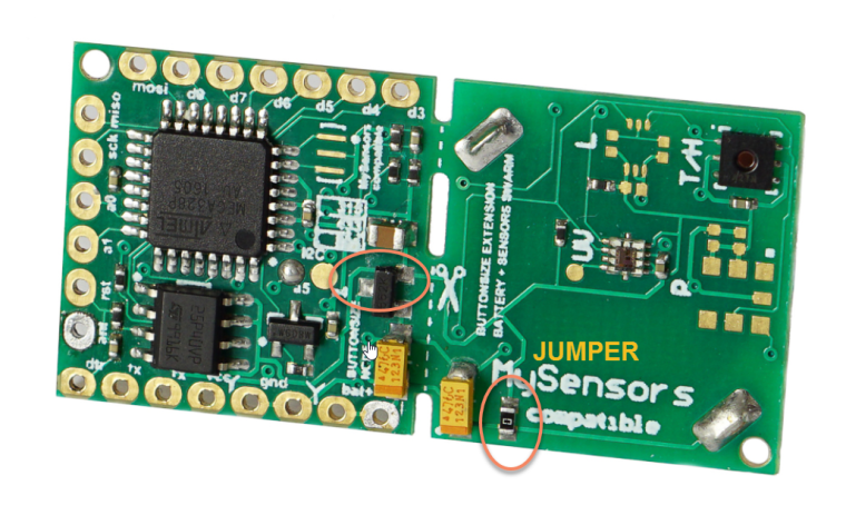
  • @Koresh another alternative would be using Si1145 it is pin-for-pin compatible with Si1132 and

    This low-power sensing family enables long battery life with standby less than 500 nA and an average power of as little as 1.2 uA with once per second real-time UV Index measurements.


    However, I still think that Si1132 can be working with the battery nicely. 0x18 register is a key:

    The COMMAND Register is the primary mailbox register into the internal sequencer. Writing to the COMMAND register is the only I2C operation that wakes the device from standby mode.

    The only question is how to put the sensor into the standby mode after all measurements are taken


  • Hardware Contributor

    @alexsh1 said in πŸ’¬ Button size radionode with sensors swarm extension:

    However, actively measuring current - 4.5mA
    This would kill 2032 very quickly

    Matter of hours I guess, it's half more than the max continuous discharge current of a CR2032.


  • @Nca78 said in πŸ’¬ Button size radionode with sensors swarm extension:

    @alexsh1 said in πŸ’¬ Button size radionode with sensors swarm extension:

    However, actively measuring current - 4.5mA
    This would kill 2032 very quickly

    Matter of hours I guess, it's half more than the max continuous discharge current of a CR2032.

    It is 4.mA for 120ms for less just for measurements
    However, I agree that this is not very battery friendly


  • Hardware Contributor

    @alexsh1 said in πŸ’¬ Button size radionode with sensors swarm extension:

    @Nca78 said in πŸ’¬ Button size radionode with sensors swarm extension:

    @alexsh1 said in πŸ’¬ Button size radionode with sensors swarm extension:

    However, actively measuring current - 4.5mA
    This would kill 2032 very quickly

    Matter of hours I guess, it's half more than the max continuous discharge current of a CR2032.

    It is 4.mA for 120ms for less just for measurements
    However, I agree that this is not very battery friendly

    Ah ok I completely misunderstood πŸ˜„ But yes seems high for a CR2032 sensor...


  • This post is deleted!


  • @Koresh,
    I tried to buy some of these on the link you provided, but couldn't do it. Do you still have this component in your stock ? I like to buy 865mhz HW/W versions.


  • @Abdu-Sahin said in πŸ’¬ Button size radionode with sensors swarm extension:

    865mhz HW/

    Hi

    They will be ready end of this week. do you need both HCW and CW versions?


  • @yury
    I like to try both 865 HW/W versions. I need sensors with long battery life and good RF distance coverage for my project. I've noticed some people suggested using only 'W' version for battery powered nodes, but from my initial experience I didn't have good distance with 'W' version.


  • @Abdu-Sahin said in πŸ’¬ Button size radionode with sensors swarm extension:

    I need sensors with long battery life and good RF distance coverage

    )) either good battery life or good coverage though... or good coverage and 2-3 AA batteries. CW is 20 mA when sending signal and HCW is about 100 mA. CR2032 battery will be drained by HCW pretty fast.
    HW/W versions have bigger footprints (Module Size:19.7X16mm) and not compatible with the "Button size".
    HCW/CW (Module Size:16X16mm) are equivalents for HW/W.


  • @yury
    I think I can start with CW version as start. Battery life is important for me.


  • @Abdu-Sahin said in πŸ’¬ Button size radionode with sensors swarm extension:

    Battery life is important

    sent you a message in the chat...


  • @yury
    You can email me if you like.
    My email is uk.asahin at gmail com


  • @Abdu-Sahin I was interested in reading your conversation about battery life etc. I hope you will continue the conversation on the forum instead of in private.

    Thanks.


  • It is possible to buy only PCB ? Upload PCB to OSH Park, or send PCB in eagle. I do not have Altium Designer... Thx


  • Contest Winner

    @Miroslav-KadanΔ› I've just uploaded latest gerbers (rfm reset pin was connected to controller, connection of si1132 was fixed, reverse battery polarity protection was added). You can place PCB order at any factory. πŸ˜‰


  • Maybe a stupid question but how do you connect the FTDI adapter? I only know the ISP pins


  • @yury @koresh

    Few months ago, I've ordered some of your nodes, which work perfectly by the way, but I needed something that could speed up testing of any sensors.
    So following our conversation on Github with Yury, I've created a PCB based on your Button size node, with a field for an extension board. The aim is to have a versatile board, and extensions that could handle virtually any sensors, like NodeManager project, but for hardware πŸ˜‰
    And it's also a first time experiment in the land of PCBs
    0_1506424891385_IMAG0468.jpg

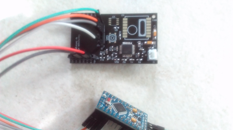
    Apart 2 errors ( maybe more in the future !), it seems to be well routed, as tests been proving, but i still not tried the FOTA function.
    Errors was a badly routed button and it seems that, after the RFM chip is soldered, communication with USBasp gets bad! Is it because SCK and MISO route ( from pin headers to atmega328 ) goes through the RFM chip before atmega ?

    You were mentioning some mods in dualoptiboot in order to flash M25P40, https://forum.mysensors.org/topic/3160/ota-flash-types-for-mysensors/43.
    Would it be possible to share these ?

    And just out of curiosity, how did you manage to solder SI7021 and TSL2561 ?
    By now, it seems like a mystery for me...


  • Contest Winner

    @getlarge said in πŸ’¬ Button size radionode with sensors swarm extension:

    after the RFM chip is soldered, communication with USBasp gets bad

    Did you solder R4 (from your schematic https://github.com/getlarge/Cosmonode/blob/master/Cosmonode_sch.pdf)? I can't find it on the boards photo.
    PS
    Will share compiled bootloader and sources soon.


  • @Koresh said in πŸ’¬ Button size radionode with sensors swarm extension:

    Sorry, picture's quality is not too good!
    R4 ( 10Kohm) is soldered. I read about that pullup resistor that is needed to sync with atmega SCK. Any other hint on what could cause that ?
    Maybe, that was a mistake when i changed the fuse? but I didn't have problem before with these settings.

    So I'll have to be patient to use M25P40!


  • @chbla said in πŸ’¬ Button size radionode with sensors swarm extension:

    Maybe a stupid question but how do you connect the FTDI adapter? I only know the ISP pins

    Can anyone quickly tell me how to do it correctly? I thought it didn't work but I'm unsure.


  • Contest Winner

    @chbla This board has standard FTDI header (see attached screenshot).

    0_1506503500534_ftdi.png

    But it also has all of ISP pins (mosi, miso, sck, rst)


  • @Koresh Might be a dumb question I am planning to work on this board, where do I find the complete part list.


  • Does any one have links to dirty pcb or OSH Park? Thanks a lot


  • Hero Member

    ^^^warning: it's an infiltration bot.


  • This post is deleted!


  • @NeverDie Not sure if you are referring to me?


  • I do not have an electronics background. I wend through the pdf files and order the parts and looks like I got the wrong resistor and capacitor or wrong part. Looks like I have to wait for an expert to comment let me know which resistor/capacitor goes where what part size. I would love to hear from someone πŸ˜‰


  • @koresh it is possible to buy this adapter (RFM69HCW -> RFM69CW) or download pcb files ?
    Thx


  • Hero Member

    @miroslav-kadanΔ› said in πŸ’¬ Button size radionode with sensors swarm extension:

    @koresh it is possible to buy this adapter or download pcb files ?
    Thx

    Go to this link and press the download button: https://www.openhardware.io/view/299/Button-size-radionode-with-sensors-swarm-extension


  • @neverdie thx, but i need adapter from RFM69HCW to RFM69CW


  • Re: πŸ’¬ Button size radionode with sensors swarm extension

    2 cr2032 winter upgrade - works nice

    Keep working at -20 Celsius in a fridge. voltage dropped from 6 Volts to 5V and keeps pretty stable while sending temperature reading every 2 minutes for 2 days now.

    0_1513507522799_f6cf3141-ea91-4c31-a320-25cb0c65b5c7-image.png

    0_1513507559378_5e5573f0-b189-4faf-8766-04a367242e68-image.png

    0_1513507573427_c616c24a-9224-4a52-80d4-7e5984ffcf86-image.png

    0_1513507583720_3d6261ad-5c43-4c25-b43d-50bf21631672-image.png

    0_1513507722585_b9338c01-ed9d-4f3e-8f39-21fd4d78f713-image.png


  • Contest Winner

    There are so many reasons to use two CR2032 batteries in series with power converter instead of one lager battery like 2450
    -CR2032 are much more widespread batteries
    -Wider temperature range
    -Stable voltage during all battery lifetime (using voltage converter)
    -Stable radio power during battery lifetime
    -Batteries give less current during transmitting so they are not "shocked" by high current.

    So I plan to create version with two CR2032 batteries holder (like on the Yury's photo) and the ultra high efficiency DC-DC converter based on the tps62745 (400 nA quiescent current, 90% efficiency)
    0_1513520436859_2017-12-17_16-39-45.png
    πŸ˜‰


  • Hero Member

    The main problem is finding a button holder that can hold two CR2032's in series. So far I've only found two. One is made by Linx, but it's definitely not ideal:
    alt text
    The other works fine, but it has a larger footprint, so I'm not presently using it. It may work well on your board, though, because your board is square, so you can use the diagonal:
    alt text
    alt text
    On the other hand, maybe you could bend down the tabs and use it as a through-hole?
    I did one where I simply cut-off the tabs and then soldered it to the board. That works, but it leaves me with an uneasy feeling as to how long it might last in that configuration. Maybe it's worth re-visiting.


  • @neverdie said in πŸ’¬ Button size radionode with sensors swarm extension:

    worth

    uh... apparently, yes. dual dip cr2032 is hard to find item on ali.


  • @koresh Hello,
    can you please update pcbdoc and schdoc files ?
    And add a pcb adapter from RFM69HCW to RFM69CW ?
    Thx Mirek


  • Contest Winner

    @miroslav-kadanΔ›
    Hello Mirek. All source files are actual, I used exactly the same files to produce latest stable version. I never share source files until I test the board. So I will share updated files (like on the latest screenshot or better) after the board will be checked and tested πŸ˜‰
    PS
    I've added rfm converter board.


  • With the default sensor and sketch I only get integer values - shouldn't this be decimals with 2 digits after the . ?
    Not sure if I have a different lib or missed something


  • This post is deleted!


  • What's the typical time you get with the default node, coin cell and the sketch on github?
    https://gist.github.com/solars/6116b78ea7ee581ecfafddb8da4a9610

    It drained within only 1 day for me


  • Mod

    is it sleeping 5 seconds only?


  • @gohan said in πŸ’¬ Button size radionode with sensors swarm extension:

    is it sleeping 5 seconds only?

    You are right, that was my mistake after testing it. However, the consumption still seems high.
    For example I'm right now testing a BME280 which I want to use in the future, with the following sketch:
    https://gist.github.com/solars/a5302f1cb60d90f89d7e37d5e23f8c4d

    It's connected to SDA/SCL and GND/V - somehow the voltage it receives with a fresh battery is already quite low, and it also doesn't last very long.


  • Mod

    you need to try to measure current while the sensor is sleeping as it should be a few uA maximum


  • @gohan I only have a normal multimeter - what's the best way to do this?
    I came across https://www.eevblog.com/projects/ucurrent/ a while ago, is it worth it?


  • Mod

    There is a project in openhardware for a current meter if you want to build one, or you could buy a newer multimeter if the one you have can not measure uA


  • @chbla said in πŸ’¬ Button size radionode with sensors swarm extension:

    multimeter

    You should be fine even with a cheap multi-meter as long as it has uA scale.

    should be around 7-10 uA and if you do not send JDEC to sleep it is 17 -19 uA.

    to send JDEC to sleep\wakeup I use
    _flash.wakeup();
    _flash.sleep();

    light sensor should be sent to sleep explicitly also.


  • Mod

    @yury not really, I have bought an Aneng cheap multimeter, but if I connect it with uA scale selected it will go out of range during node boot and cut the circuit making measurement impossible (unless you do something fancy that would make it unpractical)


  • @gohan said in πŸ’¬ Button size radionode with sensors swarm extension:

    selected it will go out of range during node boot and cut the circuit making measurement impossible

    my cheap one survives 20mA surge (RFM69 CW version) of initial communications and displays good reading afterwards. if you burned fuse inside, try replacing it temporarily with some thin wire for this uA tests.


  • Mod

    I have another cheap one that works. I didn't blow the fuse since turning it off and on it works again, it must be a software limitation


  • @yury said in πŸ’¬ Button size radionode with sensors swarm extension:

    @chbla said in πŸ’¬ Button size radionode with sensors swarm extension:

    multimeter

    You should be fine even with a cheap multi-meter as long as it has uA scale.

    should be around 7-10 uA and if you do not send JDEC to sleep it is 17 -19 uA.

    to send JDEC to sleep\wakeup I use
    _flash.wakeup();
    _flash.sleep();

    light sensor should be sent to sleep explicitly also.

    Right - but this is all in your sketch right? This is what I used:
    https://gist.github.com/solars/a5302f1cb60d90f89d7e37d5e23f8c4d


  • @Koresh would it be possible to sell this without the sensor part and RFM69? How many orders would it need?
    I don't have the possibility to produce it myself, don't need the sensors part and have a lot of RFM69s lying around..

    Thank you,
    Christoph


  • I downloaded gerber files.
    Error Message from PCB Manufacturer:
    The NC drill layer does not match with the pads of copper layer.

    Thank you,
    Attila


  • Contest Winner

    @anovak
    Hello. Do you mean main board or rfm69 adapter? It is very strange. I produced exactly these gerbers many time. πŸ€”


  • Contest Winner

    Finally I have a little time to continue this project...
    High efficient dc-dc converter works nice and double cr2032 are good. Lets go to the furher tests! 🀠
    0_1520971679297_dc_dc.jpg

    0_1520971814469_2x_cr2032.jpg


  • Thanks. The problem was solved.
    Manufactured at very low cost on pcbway, they are manufactured with "Min Track / Spacing: 5 / 5mil".
    Do you have any idea where they are manufactured cheaper?


  • Contest Winner

    New version with double battery holder and power convertor works nice.
    Power consumption in sleep mode is less than 9uA πŸ˜ƒ
    0_1521106765289_buttonsize_6v_1.jpg

    0_1521106812358_buttonsize_6v_2.jpg

    I will test it soon..


  • @koresh You only have two sensors BH1750 and Si7021. Did you try to have all four sensors and measure consumption?


  • Which pcb manufacturer do you recommend?
    I asked for a quote from Pcbway but it was expensive.
    The reason was:
    Change the 'Min Track / Spacing' value from 6 / 6mil to 5 / 5mil.

    Sorry for my bad English.


  • Contest Winner

    @anovak Unfortunately you can reduce the price of the board only if you order more boards.


  • What price can be made in 10 items?


Suggested Topics

  • 226
  • 10
  • 16
  • 2
  • 6
  • 1
  • 3
  • 4

19
Online

11.2k
Users

11.1k
Topics

112.5k
Posts