pimatic-mysensors controller plugin


  • Plugin Developer

    Created controller plugin for pimatic https://github.com/DheerajKhajuria/pimatic-MySensors

    pimatic is a home automation framework that runs on node.js. It provides a common extensible platform for home control and automation tasks.

    Uniform interface

    It defines several schemata for different home devices and sensors, so that all devices can be controlled uniform and are presented in a common interface.

    Automation by rules

    Automation tasks can be defined by rules in the form of "if this then that", where the "this" and the "that" part can be fully custemized by plugins. See the rule page for more details.
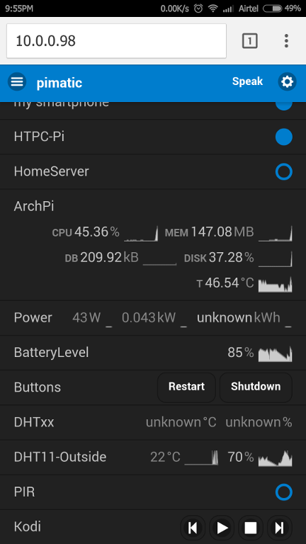
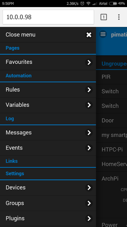
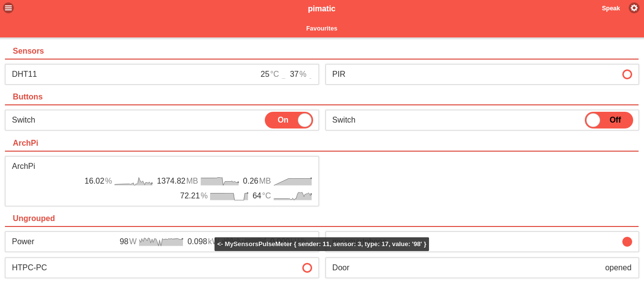
    Web-based interface

    The mobile frontend plugin provides a nice web frontend with a sensor overview, device control and rule definition. The web interface is build using express and jQuery Mobile.

    Extensible

    pimatic is extensible by various plugins adding features and integrating existing hardware and software.

    web based Interface

    Screenshot_2015-03-17-21-55-59.png

    Flexible home Automation Rules
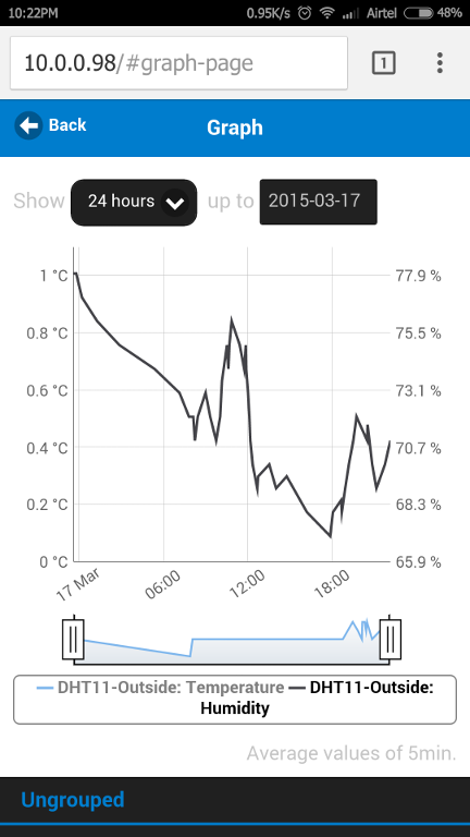
    Screenshot_2015-03-17-21-56-51.png

    Graphs

    Screenshot_2015-03-17-22-22-34.png

    Steps to install pimatic

    Now I would say let's begin with setting up Pimatic from scratch :

    You can either check the instructions on the Pimatic website http://www.pimatic.org/guide/getting-started/ or follow these steps.

    If you are using a Raspberry Pi, get the latest Wheezy Image or what ever you like from here : http://downloads.raspberrypi.org

    Then write this image with this tool Win32DiskImager to your SD-Card.

    Now set up your Pi with sudo raspi-config and do the usual updates with

    sudo apt-get update
    sudo apt-get upgrade
    sudo rpi-update

    You're ready to install Pimatic πŸ™‚ Go ahead with the following 19 steps :

    1.) wget http://nodejs.org/dist/v0.10.24/node-v0.10.24-linux-arm-pi.tar.gz -P /tmp
    2.) cd /usr/local
    3.) sudo tar xzvf /tmp/node-v0.10.24-linux-arm-pi.tar.gz --strip=1
    4.) sudo apt-get install build-essential
    5.) mkdir /home/pi/pimatic-app
    6.) cd /home/pi/
    7.) npm install pimatic --prefix pimatic-app --production
    8.) cd pimatic-app
    9.) cp node_modules/pimatic/config_default.json config.json
    10.) sudo nano /home/pi/pimatic-app/config.json (very important :insert admin password!!! otherwise pimatic won't start and comes up with an error message)

    11.) sudo chmod 777 /home/pi/pimatic-app/
    12.) sudo reboot
    13.) cd ./pimatic-app/node_modules/pimatic
    14.) sudo npm link
    15.) wget https://raw.github.com/pimatic/pimatic/master/install/pimatic-init-d
    16.) sudo cp pimatic-init-d /etc/init.d/pimatic
    17.) sudo chmod +x /etc/init.d/pimatic
    18.) sudo chown root:root /etc/init.d/pimatic
    19.) sudo update-rc.d pimatic defaults

    Now you are ready to start pimatic for the first time!
    There are three ways to start pimatic generally.

    Automatically at system start (since we daemonized Pimatic with the entries in init-d)
    With the command sudo service pimatic start (will run Pimatic as daemon / service in the background)
    With the command sudo pimatic.js (can be executed everywhere, since we globalized it)
    For the first start i recommend to use option 3 since Pimatic will do some compiling and setting up things. this may take a while, so you are able to watch the debug outputs on the console screen and see what Pimatic is doing actually.
    If you run sudo "service pimatic start" you won't get any debug messages since Pimatic will run in the background.

    When Pimatic is through with all the setup stuff, you will see a message like that :

    Now you can access the Pimatic gui via browser by entering the IP of your pi and go ahead with the further setup = > Step 2 - GUI overview

    For pimatic plugins : http://pimatic.org/pages/plugins/

    Support following pimatic-mysensors sensors


  • Admin

    Great work @Dheeraj!

    @bjornhallberg
    Please update your overview thread.


  • Hero Member

    @hek Done!

    @Dheeraj Fantastic! Pimatic seems great, especially since it has support for pilight. A real cheap all-in-one solution for those that still want to use their old 433MHz devices and keep adding mysensors modules.


  • Plugin Developer

    @hek @bjornhallberg
    added support for relay-actuator module πŸ™‚

    Module supported..
    Temperature and Humidity ( http://mysensors.org/build/humidity)
    motion ( http://mysensors.org/build/motion )
    Relay-Actuator ( http://www.mysensors.org/build/relay )


  • I canΒ΄t make mysensors plugin works in pimatic. I added this lines at plugins session of config.json with no sucess:

    {
    "plugin": "MySensors",
    "driver": "serialport",
    "protocols": "1.4.1",
    "driverOptions": {
    "serialDevice": "/dev/ttyUSB0", # #'/dev/ttyUSBx' if using serial Gateway
    "baudrate": 115200
    }
    }

    I received error messages like syntax error.


  • Plugin Developer

    @ricardot said:

    let me the exact error msg.


  • @Dheeraj said:

    @ricardot said:

    let me the exact error msg.

    15:16:12.055 [pimatic] Starting pimatic version 0.8.45
    15:16:15.227 [pimatic] Startup error: Error: Parse error on line 80:
    15:16:15.227 [pimatic]>..."/dev/ttyUSB0", "#" "#""/dev/ttyUSBx" "i
    15:16:15.227 [pimatic]>-----------------------^
    15:16:15.227 [pimatic]>Expecting 'EOF', '}', ':', ',', ']', got 'STRING'
    15:16:15.227 [pimatic]> at Object.parseError (/usr/local/pimatic-app/node_modules/pimatic/node_modules/cjson/node_modules/jsonlint/lib/jsonlint.js:55:11)
    15:16:15.227 [pimatic]> at Object.parse (/usr/local/pimatic-app/node_modules/pimatic/node_modules/cjson/node_modules/jsonlint/lib/jsonlint.js:132:22)
    15:16:15.227 [pimatic]> at Object.exports.parse (/usr/local/pimatic-app/node_modules/pimatic/node_modules/cjson/node_modules/jsonlint/lib/jsonlint.js:417:53)
    15:16:15.227 [pimatic]> at Object.exports.parse (/usr/local/pimatic-app/node_modules/pimatic/node_modules/cjson/index.js:88:28)
    15:16:15.227 [pimatic]> at Framework._loadConfig (/usr/local/pimatic-app/framework.coffee:96:24)
    15:16:15.227 [pimatic]> at new Framework (/usr/local/pimatic-app/framework.coffee:54:8)
    15:16:15.227 [pimatic]> at /usr/local/pimatic-app/startup.coffee:48:21
    15:16:15.227 [pimatic]> at tryCatch1 (/usr/local/pimatic-app/node_modules/pimatic/node_modules/bluebird/js/main/util.js:43:21)
    15:16:15.227 [pimatic]> at Function.Promise$_Try (/usr/local/pimatic-app/node_modules/pimatic/node_modules/bluebird/js/main/promise.js:233:11)
    15:16:15.227 [pimatic]> at Object.module.exports.startup (/usr/local/pimatic-app/startup.coffee:47:10)
    15:16:15.227 [pimatic]> at run (/usr/local/pimatic-app/node_modules/pimatic/pimatic.js:15:24)
    15:16:15.227 [pimatic]> at Object.<anonymous> (/usr/local/pimatic-app/node_modules/pimatic/pimatic.js:20:3)
    15:16:15.227 [pimatic]> at Module._compile (module.js:456:26)
    15:16:15.227 [pimatic]> at Object.Module._extensions..js (module.js:474:10)
    15:16:15.227 [pimatic]> at Module.load (module.js:356:32)
    15:16:15.227 [pimatic]> at Function.Module._load (module.js:312:12)
    15:16:15.227 [pimatic]> at Function.Module.runMain (module.js:497:10)
    15:16:15.227 [pimatic]> at startup (node.js:119:16)
    15:16:15.227 [pimatic]> at node.js:902:3
    15:16:15.274 [pimatic] exiting...


  • I removed the # #'/dev/ttyUSBx' if using serial Gateway

    So I got this:

    15:17:54.005 [pimatic] Starting pimatic version 0.8.45
    15:17:58.403 [pimatic] loading plugin: "pimatic-cron" (0.8.5)
    15:18:00.793 [pimatic] loading plugin: "pimatic-mobile-frontend" (0.8.44)
    15:18:05.848 [pimatic] loading plugin: "pimatic-mail" (0.8.2)
    15:18:08.301 [pimatic] Installing: "MySensors"
    15:18:16.958 [pimatic, npm] http GET https://registry.npmjs.org/pimatic-MySensors
    15:18:18.741 [pimatic, npm] http 404 https://registry.npmjs.org/pimatic-MySensors
    15:18:18.848 [pimatic, npm] ERR! 404 'pimatic-MySensors' is not in the npm registry.
    15:18:18.872 [pimatic, npm] ERR! 404 You should bug the author to publish it
    15:18:18.896 [pimatic, npm] ERR! 404
    15:18:18.914 [pimatic, npm] ERR! 404 Note that you can also install from a
    15:18:18.955 [pimatic, npm] ERR! 404 tarball, folder, or http url, or git url.
    15:18:18.964 [pimatic, npm] ERR! System Linux 3.12.28+
    15:18:18.986 [pimatic, npm] ERR! command "/usr/local/bin/node" "/usr/local/bin/npm" "install" "pimatic-MySensors"
    15:18:19.005 [pimatic, npm] ERR! cwd /usr/local/pimatic-app
    15:18:19.025 [pimatic, npm] ERR! node -v v0.10.24
    15:18:19.034 [pimatic, npm] ERR! npm -v 1.3.21
    15:18:19.056 [pimatic, npm] ERR! code E404
    15:18:19.161 [pimatic, npm] ERR!
    15:18:19.192 [pimatic, npm] ERR! Additional logging details can be found in:
    15:18:19.205 [pimatic, npm] ERR! /usr/local/pimatic-app/npm-debug.log
    15:18:19.213 [pimatic, npm] ERR! not ok code 0
    15:18:19.312 [pimatic] Error running "npm install pimatic-MySensors"
    15:18:20.192 [pimatic-cron] the time is: Mon Feb 16 2015 15:18:20 GMT+0000 (UTC)
    15:18:20.996 [pimatic-mobile-frontend] packing static assets
    15:18:22.251 [pimatic-mobile-frontend] packing static assets finished
    15:18:22.273 [pimatic-mobile-frontend] rendering html
    15:18:44.851 [pimatic-mobile-frontend] rendering html finished
    15:18:44.989 [pimatic] listening for http-request on port 80...


  • Plugin Developer

    Since i haven't register mysensors with npm. that's the reason it is giving you the error. As a work around try download & manually installing pimatic-MySensors in node_module in pimatic-app folder.. Here other plugins are also installed like Pimatic-mobile-fontend etc.. Pimatic should be able to pick it up..
    I will try to fix this issue meanwhile.

    Let me know if it's works.


  • I manually installed the pimatic-mysensors, seems it works, but I'm receiving this message:

    13:46:47.360 [pimatic] Cannot find module 'bluebird'

    Later I added two devices, a PIR and a relay-switch, and I'm receiving this message:

    13:46:49.289 [pimatic] no plugin found for device "Switch" of class "MySensorsSwitch"!
    13:46:49.305 [pimatic] no plugin found for device "PIR" of class "MySensorsPIR"!


  • Plugin Developer

    @ricardot said:

    atic] Cannot find module 'bluebird'

    Later I added two devices, a PIR and a relay-switch, and I'm receiving this message:

    13:46:49.289 [pimatic] no plugin found for device "Switch" of class "MySensorsSwitch"!
    13:46:49.305 [pimatic] no plugin found for device "PIR" of

    give me sometime will fix this issue.


  • Plugin Developer

    @ricardot

    I have fixed the issues, plugin published to public npm registry . now i think it should work perfectly


  • @Dheeraj

    It worked now, but I had to change the ttyUSB0 to ttyACM0. I'm using the uno for the gateway.


  • Dheeraj,

    When we can expect more variables available to mysensors plugin? I miss a simple on off switch.

    Thanks!


  • Plugin Developer

    @ricardot
    contact/door/light mysensor add to list.. just check πŸ™‚
    upload-58e0611e-710b-4a9a-9337-60282ed10131


  • @Dheeraj

    This is my first try at getting MySensors to work.

    I've connected a SerialGateway to the Pi, and configured a DHT22 sensor. But no values are recorded.

    Logs from the pi:

    <- I_LOG_MESSAGE 0;0;3;0;9;read: 255-255-0 s=255,c=3,t=3,pt=0,l=0:
    <- I_ID_REQUEST 255;255;3;0;3;
    <- I_LOG_MESSAGE 0;0;3;0;9;read: 255-255-0 s=255,c=3,t=3,pt=0,l=0:
    <- I_ID_REQUEST 255;255;3;0;3;

    Serial output from the sensor:

    req node id
    send: 255-255-0-0 s=255,c=3,t=3,pt=0,l=0,st=ok:
    T: 22.70
    req node id
    send: 255-255-0-0 s=255,c=3,t=3,pt=0,l=0,st=ok:
    H: 31.10
    req node id
    send: 255-255-0-0 s=255,c=3,t=3,pt=0,l=0,st=ok:
    H: 31.00

    What can I be doing wrong? Seems like the sensor is requesting a node ID but not getting any?

    Thank you for any kind of response!

    Regards, Martin


  • Plugin Developer

    @gogomartin

    Currently mysensors plugin only support static node id. Try configuring static node id in sensor code. Hint.. Gw. Begin (null, node id)

    Let me know if it's works


  • Dheeraj,

    Good work!

    Is possible to send sensor battery level info?


  • Plugin Developer

    @ricardot

    battery sensor visualization is WIP..


  • hey,
    I really like your plugin now that I finally managed to get everything working. πŸ™‚
    But I would also like to use a BH1750 Light sensor with your plugin. I made a sensorbox with PIR to switch on lights for a minute when movement is detected, but I only want to switch on light when it's dark enough. Is it planned to add support for this?


  • Plugin Developer

    This post is deleted!

  • Plugin Developer

    @ricardot added support for battery level stats 0.8.9


  • Plugin Developer

    @Ralf-H sure will add support for light sensor


  • I would like to help you make a color picker for rgb leds and a slider for random pwm outputs πŸ˜„
    -edit-

    deviceClasses = [
            MySensorsDHT
            MySensorsBMP
            MySensorsPIR
            MySensorsSwitch
            MySensorsPulseMeter
            MySensorsButton
            MySensorBattery
            MySensorsDevDimmer
          ]
    

    and

     class MySensorsDevDimmer extends env.devices.DimmerActuator
    
        constructor: (@config,lastState, @board) ->
          @id = config.id
          @name = config.name
          @_state = lastState?.state?.value
          env.logger.info "MySensorsDevDimmer" , @id , @name, @_state
    
          @board.on('rfValue', (result) =>
            if result.sender is @config.nodeid and result.type is
            V_LIGHT and result.sensor is @config.sensorid
              state = (if parseInt(result.value) is 1 then on else off)
              env.logger.info "<- MySensorDevDimmer " , result
              @_setState(state)
            )
          super()
    
        changeStateTo: (state) ->
          assert state is on or state is off
          if state is true then _state = 1  else _state = 0
          datas = {}
          datas =
          {
            "destination": @config.nodeid,
            "sensor": @config.sensorid,
            "type"  : V_LIGHT,
            "value" : _state,
            "ack"   : 1
          }
          @board._rfWrite(datas).then ( () =>
            @_setState(state)
          )


    But i get :
    Could not initialize the plugin "mysensors": MySensorsDevDimmer is not defined

    I know that this won`t actually work because of the :

     state = (if parseInt(result.value) is 1 then on else off) 
    

    and the :

      if state is true then _state = 1  else _state = 0
    

    What I don't get is why does it throw me that error. (Don't go hard on me, I just learned the basics of coffee script only for this)


  • Plugin Developer

    @Vladut-Grecu said:

    if state is true then _state = 1 else

    check the pimatic-daemon.log file and what kind of error exception your are getting . not sure if you have enable the "logLevel": "debug", in config.json for pimatic.

    Also, you need to add entry in device-config-schema.coffee schema file.
    if nothing works share the log file with me..

    I'm also new to coffee or nodejs and struggled a lot understanding the coffee script , basically, still in learning phase..


  • @Dheeraj, I have been looking all day for how to configure static node id , meanwhile I heard of mysensors last night so pardon me if I didn't find the doc that explain it. Can you point me in the right direction?


  • Plugin Developer

    @Sebastien-Vayrette-Gavard said:

    I didn't find the doc that explain it. Can you point me in the right di
    follow the below instruction

    for pimatic installation:
    http://www.pimatic.org/guide/getting-started/installation/

    plugin instruction:
    https://github.com/DheerajKhajuria/pimatic-mysensors


  • Hello, I am new with controler. I already have some temperature sensors and other controls, but until now I did not use any controller,
    I am not familiar with linux, and I need help with instalation of controler on raspbery 2.
    I am done with OS instalation, I am using image NOOBS.
    I try to install Pimatic acording this procedure, http://pimatic.org/guide/getting-started/installation/
    And now I am not sure what next.
    Please can anybody help me?
    Thanks


  • @jurasek I found out that pimatic installation in the website quite general.
    for more details, you can use following link for the forum.
    it gives me clear idea and more details step by step


  • Thanks, I have a pimatic runing now. I would like connect NRF24 directly to the RPI is this possible? How can I setup mysensors plugin for this?

    Thanks


  • Plugin Developer

    @jurasek connecting NRF24L01 to RPi directly is possible you will find good amount of references if you search this form.


  • Hello @Dheeraj
    Any info about how to setup a pulsecount sensor?


  • @Dheeraj is the light sensor supported? I am getting

    20:32:05.069 [pimatic] warn: no plugin found for device "Light1" of class "MySensorLight"!

    when starting pimatic with

    {
          "id": "Light1",
          "name": "Lighti1",
          "class": "MySensorLight",
          "nodeid": 11,
          "sensorid": 0
        }
    

    yet I am able to see the sensor in pimatic's logs

    <- I_LOG_MESSAGE 0;0;3;0;9;read: 11-11-0 s=0,c=1,t=23,pt=2,l=2:39


  • Plugin Developer

    @Sebastien-Vayrette-Gavard said:

    yet I am able

    kindly change the "class" name as "MySensorsLight" . please note it has a 's' in between.


  • Plugin Developer

    @Fredrik-Carlsson

    frankly, i couldn't check pulsecount using actual power meter. although i can simulate it πŸ™‚ . It's custom made according to my need. I can modify it as per http://www.mysensors.org/build/pulse_power build easily.

    currently it only supports "V_WATT" message.


  • Good morning @Dheeraj
    Do you have any example for how you are configuring it? I have made a node with the "original" sketch and configured it with sensor array [0,1,2] in pimatic. I see the device, with parameters w/kw/kWh but no info comes in. Are you using a custom sketch then or how is your setup working?
    I think one of the nicest things about pimatic is the graphing functionality. I want to log and and check how the heating is distributed throughout my house and at which consumption depending on heatpump / woodstove settings


  • @Dheeraj maybe you can fix the example here for lazy eyes/asses like me. I just copied and paste and didn't notice the missing "s" Thank you so much for the quick support and the great plugin.


  • Plugin Developer

    @Fredrik-Carlsson said:

    think one of the nicest things about pimatic is the graphing functionality. I want to log and and check how the heating is distributed throughout my house and at which consumption depending on heatpump / woodstove set

    since i don't have home laptop with me. otherwise , i could have shared the custom sketch with you. but what i remember is that it sends V_WATT message with wattage usage and calculate KW and KWh ( still broken ) at controller end ( pimatic ).

    meanwhile, i'm fixing the pulsemeter code which will be compatible with actual sketch, wait for 1 or 2 days. Also, we will be able to see battery status (optional) with sensor devices.

    one thing you missed here is that pimatic is browser based also have the "automation by rules" functionality which is awesome. also you can try various plugins available with pimatic. http://www.pimatic.org/pages/plugins/


  • @Dheeraj I wait patiently then πŸ™‚
    Yes the more im digging in to pimatic the more i like it and feel that it fits my needs perfectly


  • Yesterday was great update (0.8.14). Now battery level is connected with device as regular attribute. Great job, @Dheeraj! Thanks a lot!

    battery.png


  • Plugin Developer

    newer version (0.8.15 ) of plugin release . support Acronym for devices . improves user experience.


  • @Fredrik-Carlsson info you havent got one, please check my development git

    • Pulse sensor ( Watt, KWh and Ampere )
      {
      "id": "EnergySensor,
      "name": "Energy Sensor",
      "class": "MySensorsPulseMeter",
      "nodeid": 3,
      "batterySensor": true,
      "sensorid": 1,
      "appliedVoltage" : 220
      }


  • Yes saw it on github, very interesting. Will try as soon as I am home again


  • @Fredrik-Carlsson please try it, please notice me if you find any bugs.
    I'm in the middle of pull request to @Dheeraj


  • Hello
    haven't had the opportunity to test yet.
    will try to find time tomorrow


  • @Dheeraj said:

    newer version (0.8.15 ) of plugin release . support Acronym for devices . improves user experience.

    Hello @Dheeraj,

    Could you tell me which commit was connected with 0.8.15? I am little bit confused because your github is still contains 0.8.14 but it looks newer when 0.8.15.


  • Plugin Developer

    @Mad-Moo latest code 0.8.17 is pushed to github. now everything is sync.


  • @funky81
    Hello. I have had a hard time testing this. Is the future for the pulsesensor implemented in 0.8.17 official plugin?

    If not, how get the latest commit in to pimatic? Have tried to git clone the plugin and then npm install inside the folder, but then none of the sensors shows up in pimatic (the plugin is not active)

    With official 0.8.17 the arduino sketch just come in to an endless loop where it wants the latest pulsecount = no answer from pimatic


  • Hello,

    Very nice plugin.

    Is there any chance in the future to support the ethernet gateway?

    It would be great if we could connected simultaneously to a serial and ethernet gateway from the same pimatic server.
    so we could cover remote places..!!!!


  • Plugin Developer

    New version of plugin available. 0.8.21.

    and a video to showcase its capability..

    MySensors & Pimatic Duo – 04:48
    β€” Dheeraj Khajuria


  • @Dheeraj
    Nice! One question: Could you maybe disconnect your repository from pimatic-plugin-template?
    http://stackoverflow.com/questions/16052477/delete-fork-dependency-of-a-github-repository

    With the fork connected its hard to fork. πŸ˜‰


  • Plugin Developer

    @Oitzu sure will do it need some time..


  • Hi, I am using the mysensors-pimatic system and it works great. Now, I am using an optocoupler to simulate some buttons being pressend, and at the moment I am using the relay sketch for that. That works great, but it gives me on/off switches in pimatic. However, I only press the button momentarily. So I would need more a momentary button in pimatic. Something that does not switch but I still can press. So three questions:

    1. Is there a way to have an "ordinary" button in pimatic (not on/off)? Something I press only? This on/off switch works (everytime I switch on or off it simulates on button pressed on my optocoupler), but it is not really what I am looking for.
    2. Is there some code for a momentary button in mysensors? The relay code I am using works great. I adapted in a way that it swtiches the optocoupler on and 50ms later automatically off. Works great, but I was wondering if there was a more elegant way to do it.
    3. If there is no code for a momentary button for pimatic, where would I start looking if I'd want to contribute code?

    Cheers!


  • Hey karl261,

    1.) Yes there is a ordinary button in pimatic. The base-class is called "ButtonsDevice" if i remember correctly.
    2.) The MySensors Plugin also seems to implement this.
    See: https://github.com/DheerajKhajuria/pimatic-mysensors
    Search for: Binary Button
    3.) Depends at which point you want to contribute code.
    For the mysensors plugin: https://github.com/DheerajKhajuria/pimatic-mysensors
    For the Pimatic framework: https://github.com/pimatic/pimatic
    Make also sure to read the howto @ www.pimatic.org and visit the forum forum.pimatic.org.


  • Plugin Developer

    @karl261 using ButtonsDevice as mentioned by Oitzu, you can achieve the point no. 1 . non off/on switch..

    upload-9622ca50-7f41-488d-b9db-64391bbf0479

    
    {
          "id": "mode",
          "name": "TV Mode",
          "class": "ButtonsDevice",
          "buttons": [
            {
              "id": "PVR",
             "text": "PVR"
            },
            {
              "id": "HTPC",
              "text": "HTPC"
            },
            {
              "id": "Chromecast",
              "text": "Chromecast"
            },
            {
              "id": "testing",
              "text": "RainBowCycle"
            },
          ]
        },


    for point no. 2 you can use pimatic IFTTT rules to control (*hidden * relay switch button) moreover you can switch off optocoupler after 50 ms using rules.

    1. if you have some special requirement you are welcome to contribute..


  • Hi guys. Thanks for the replies. This seems to work. I created a button and made a rule "if button XY pressed then toggle AB". So I suppose I leave the relay device as is, just remove it from my pimatic page (out of sight) and move in the button instead. IS that right?

    Very cool indeed!


  • Hi there, I have problem that appears recently. I hope somebody can point me in the right direction.

    I had my setup running for the past two weeks without any problems. No changes in hardware. Now the following happened:

    Suddenly out of nowhere pimatic stop transmitting/receiving. Just like this. No error message. Pimatic frontend working finde. But no data going out to or coming in from the serial gateway.

    I checked all logs: Nothing. I re-started pimatic: No success. All logs normal. I restarted the pi2: Nothing. All logs normal. I unplugged/replugged the arduino nano: Nothing. No success.

    Then I shutdown the pi2, I pulled the power cable, I put it back in and voila: Everything worked normally. Still nothing in any logs. Unfortunately, now about 24h later, the same issue.

    What is happening there? How can I debug that? I also tried resetting the usb:

    echo 0 > /sys/bus/usb/devices/1-1.5/authorized
    echo 1 > /sys/bus/usb/devices/1-1.5/authorized
    Nothing.

    What can I do? Why was it running perfectly for two weeks?

    I changed back to a super simple pimatic config with just one device, but still the same issues.

    What to do? Please advice!


  • @karl261 said:

    I checked all logs: Nothing. I re-started pimatic: No success. All logs normal. I restarted the pi2: Nothing. All logs normal. I unplugged/replugged the arduino nano: Nothing. No success.

    What can I do? Why was it running perfectly for two weeks?

    What to do? Please advice!

    Hi there! Spontaneously i have no idea what could be going wrong, only chance is to narrow down the problem.
    Based on your writing i assume you are using the serial gateway to interface with the mysensors network?
    Did you try to enable the debug output in pimatic?
    You could try to stop pimatic, detach usb, attach usb and look directly with screen on the serial device what the gateway is doing.

    screen <device>


  • This is the only thing I see in the screen

    0;0;3;0;9;gateway started, id=0, parent=0, distance=0
    0;0;3;0;14;Gateway startup complete.
    

    Then nothing else. No signal recieved, even if I now my sensors are sending, but also, when I am sending something via pimatic, no send message.


  • @karl261 maybe a defect nrf24 module? The serial connection to the nano seems to work and should normaly show received messages.
    Do you have any spare modules laying arround?


  • @Oitzu that is possible. And also weird. It was working for three weeks without problem. Is there no way to get an error message from the nrf24? Why does it work after unplugging the pi? Why does it not help to reset the sub bus, which should power cycle the nano and the radio module?
    I have some nrf24 around, but the installation is in a remote place which I can only access from time to time. That's why I installed mysensors and piratical in the first place. To remote control some things. So three weeks before I can try another radio. I hoped I could reset the system somehow to be able to use my system in the meantime...


  • @karl261 said:

    @Oitzu that is possible. And also weird. It was working for three weeks without problem. Is there no way to get an error message from the nrf24? Why does it work after unplugging the pi? Why does it not help to reset the sub bus, which should power cycle the nano and the radio module?
    I have some nrf24 around, but the installation is in a remote place which I can only access from time to time. That's why I installed mysensors and piratical in the first place. To remote control some things. So three weeks before I can

    Well i can only guess whats the problem or whats the reason to it.
    A faulty device can fail at the first day or just after 3 weeks.
    The mysensors libs will check at start time the communication with the nrf24 module. If the communication don't work it will give out a "check wires" instead of the "Gateway startup complete.".

    Maybe the difference between the full power cycle and the nano power cycle is the duration of the power cycle?
    I can guess that the full power cycle left the nrf24 module for a longer time without power?
    A longer power down of the nano would result in more time for the caps to discharge?


  • @Oitzu thanks a lot for your help. I appreciate it.

    Some more observations:

    • If I reboot the pi, I get
    0;0;3;0;9;gateway started, id=0, parent=0, distance=0
    0;0;3;0;14;Gateway startup complete.
    

    in the screen session.

    • However, if I do
    echo '1-1.5' > /sys/bus/usb/drivers/usb/unbind
    echo '1-1.5' > /sys/bus/usb/drivers/usb/bind
    

    which should power cycle the usb device I do not see anything in the screen session. Which means that the arduino nano was not power cycled.

    However I do see that something happened in the log file:

    Nov 12 17:31:40 raspberrypi kernel: [  300.831131] ftdi_sio ttyUSB0: FTDI USB Serial Device converter now disconnected from ttyUSB0
    Nov 12 17:31:40 raspberrypi kernel: [  300.839881] ftdi_sio 1-1.5:1.0: device disconnected
    Nov 12 17:31:46 raspberrypi kernel: [  306.271337] ftdi_sio 1-1.5:1.0: FTDI USB Serial Device converter detected
    Nov 12 17:31:46 raspberrypi kernel: [  306.278553] usb 1-1.5: Detected FT232RL
    Nov 12 17:31:46 raspberrypi kernel: [  306.283631] usb 1-1.5: FTDI USB Serial Device converter now attached to ttyUSB0
    

    So, what does it mean? I don't understand. Maybe there is something wrong with the pi's USB hub? Which is only reset when I pull the plug? But then the wifi should also not work, because it is sitting on the same USB hub.

    /:  Bus 01.Port 1: Dev 1, Class=root_hub, Driver=dwc_otg/1p, 480M
        |__ Port 1: Dev 2, If 0, Class=Hub, Driver=hub/5p, 480M
            |__ Port 1: Dev 3, If 0, Class=Vendor Specific Class, Driver=smsc95xx, 480M
            |__ Port 4: Dev 4, If 0, Class=Vendor Specific Class, Driver=rtl8192cu, 480M
            |__ Port 5: Dev 5, If 0, Class=Vendor Specific Class, Driver=ftdi_sio, 12M
    

    I really don't like that there is no error message nowhere...

    Is there any other place I could ask for help?


  • Ok, so I found a way to reset the usb bus using hub-ctrl.c. There is interesting information here:
    https://www.raspberrypi.org/forums/viewtopic.php?f=29&t=93463
    https://github.com/codazoda/hub-ctrl.c
    https://www.raspberrypi.org/forums/viewtopic.php?t=71044&p=513908
    http://raspberrypi.stackexchange.com/questions/27903/usb-power-cycling-problem
    So, in my case I can issue the command

    ./hub-ctrl -h 0 -P 5 -p 0 ; sleep 3; ./hub-ctrl  -h 0 -P 5 -p 1
    

    and it does indeed reset the right port, because if I open now the screen sessoin I get the usual

    0;0;3;0;9;gateway started, id=0, parent=0, distance=0
    0;0;3;0;14;Gateway startup complete.
    

    BUT: Still the thing is not sending receiving anything. WHY?


  • Tried to extend the sleep between power down and up?


  • Yes, I also tried with 30 seconds. Longer?


  • Well.. i think you can't lose anything. πŸ˜„
    Will be hard to debug after that without access to the actual hardware.


  • So, I made some modifications to the Serial Gateway sketch so it includes

    radio.printDetails();
    

    I see that it is looping though the loop function, but I actually see NO ouput from this function. What does this mean? That there is actually no radio connected? Wouldn't it say something like "no radio" or so?


  • Good point. I had not, now I have. But still, there is absolutely 0 output from this. The only message I see is the "Gateway startup complete" stuff.


  • I use Pimatic for more than a year now and I am using the Mysensors plugin 0.8.21 for more than 4 weeks now.
    I use a serial gateway based on a arduino nano and a NRF24 radio.

    I have already several sensors running without troubles and it appear to be stable.

    What I see from your information is that the serial gateway is communicating, but seems to recieve nothing from your sensors.

    If you can see on the PI that your gateway is started up, then the PI is able to recieve the information.

    I debugged my serial gateway using the
    serial monitor in the Arduino ide. This is also the way to test your sensors. In the serial monitor you can see if they are connecting to the gateway and sending information.


  • Hi,

    After using OpenHAB for quite some time, I've made the transition to Pimatic.
    I've got a pro mini 3V running on 2 AA batteries with a DS18B20-temp-sensor.
    I would like to be able to display the battery level but am having some trouble.
    I combined the temp and battery sensor into 1, but the battery status isn't being analyzed properly.
    When I restart the node it transmits a value of 12 and shortly after that a value of 0.

    Any ideas how to solve this?
    Is this related to pimatic and the format in which it receives battery data or is it simply a fault in my code?

    Thanks in advance!

    This is my code:

    /**
     * The MySensors Arduino library handles the wireless radio link and protocol
     * between your home built sensors/actuators and HA controller of choice.
     * The sensors forms a self healing radio network with optional repeaters. Each
     * repeater and gateway builds a routing tables in EEPROM which keeps track of the
     * network topology allowing messages to be routed to nodes.
     *
     * Created by Henrik Ekblad <henrik.ekblad@mysensors.org>
     * Copyright (C) 2013-2015 Sensnology AB
     * Full contributor list: https://github.com/mysensors/Arduino/graphs/contributors
     *
     * Documentation: http://www.mysensors.org
     * Support Forum: http://forum.mysensors.org
     *
     * This program is free software; you can redistribute it and/or
     * modify it under the terms of the GNU General Public License
     * version 2 as published by the Free Software Foundation.
     *
     *******************************
     *
     * DESCRIPTION
     *
     * Example sketch showing how to send in DS1820B OneWire temperature readings back to the controller
     * http://www.mysensors.org/build/temp
     */
    
    #include <MySensor.h>  
    #include <SPI.h>
    #include <DallasTemperature.h>
    #include <OneWire.h>
    
    #define COMPARE_TEMP 1 // Send temperature only if changed? 1 = Yes 0 = No
    #define ONE_WIRE_BUS 3 // Pin where dallase sensor is connected 
    #define MAX_ATTACHED_DS18B20 16
    unsigned long SLEEP_TIME = 30000; // Sleep time between reads (in milliseconds)
    OneWire oneWire(ONE_WIRE_BUS); // Setup a oneWire instance to communicate with any OneWire devices (not just Maxim/Dallas temperature ICs)
    DallasTemperature sensors(&oneWire); // Pass the oneWire reference to Dallas Temperature. 
    MySensor gw;
    float lastTemperature[MAX_ATTACHED_DS18B20];
    int numSensors=0;
    int node_id = 12;
    int BATTERY_SENSE_PIN = A0;  // select the input pin for the battery sense point
    int oldBatteryPcnt = 0;
    boolean receivedConfig = false;
    boolean metric = true; 
    // Initialize temperature message
    MyMessage msg(0,V_TEMP);
    
    void setup()  
    { 
      // Startup up the OneWire library
      sensors.begin();
      // requestTemperatures() will not block current thread
      sensors.setWaitForConversion(false);
    
      // use the 1.1 V internal reference
    #if defined(__AVR_ATmega2560__)
       analogReference(INTERNAL1V1);
    #else
       analogReference(INTERNAL);
    #endif
    
     // Startup and initialize MySensors library. Set callback for incoming messages. 
      gw.begin(NULL, node_id);
    
      // Send the sketch version information to the gateway and Controller
      gw.sendSketchInfo("Temperature Sensor met battery", "1.0");
    
      // Fetch the number of attached temperature sensors  
      numSensors = sensors.getDeviceCount();
    
      // Present all sensors to controller
      for (int i=0; i<numSensors && i<MAX_ATTACHED_DS18B20; i++) {   
         gw.present(i, S_TEMP);
      }
    }
    
    
    void loop()     
    {     
       // get the battery Voltage
       int sensorValue = analogRead(BATTERY_SENSE_PIN);
       #ifdef DEBUG
       Serial.println(sensorValue);
       #endif
       
       // 1M, 470K divider across battery and using internal ADC ref of 1.1V
       // Sense point is bypassed with 0.1 uF cap to reduce noise at that point
       // ((1e6+470e3)/470e3)*1.1 = Vmax = 3.44 Volts
       // 3.44/1023 = Volts per bit = 0.003363075
       float batteryV  = sensorValue * 0.003363075;
       int batteryPcnt = sensorValue / 10;
    
       #ifdef DEBUG
       Serial.print("Battery Voltage: ");
       Serial.print(batteryV);
       Serial.println(" V");
    
       Serial.print("Battery percent: ");
       Serial.print(batteryPcnt);
       Serial.println(" %");
       #endif
    
       if (oldBatteryPcnt != batteryPcnt) {
         // Power up radio after sleep
         gw.sendBatteryLevel(batteryPcnt);
         oldBatteryPcnt = batteryPcnt;}
         
      // Process incoming messages (like config from server)
      gw.process(); 
    
      // Fetch temperatures from Dallas sensors
      sensors.requestTemperatures();
    
      // query conversion time and sleep until conversion completed
      int16_t conversionTime = sensors.millisToWaitForConversion(sensors.getResolution());
      // sleep() call can be replaced by wait() call if node need to process incoming messages (or if node is repeater)
      gw.sleep(conversionTime);
    
      // Read temperatures and send them to controller 
      for (int i=0; i<numSensors && i<MAX_ATTACHED_DS18B20; i++) {
     
        // Fetch and round temperature to one decimal
        float temperature = static_cast<float>(static_cast<int>((gw.getConfig().isMetric?sensors.getTempCByIndex(i):sensors.getTempFByIndex(i)) * 10.)) / 10.;
     
        // Only send data if temperature has changed and no error
        #if COMPARE_TEMP == 1
        if (lastTemperature[i] != temperature && temperature != -127.00 && temperature != 85.00) {
        #else
        if (temperature != -127.00 && temperature != 85.00) {
        #endif
     
          // Send in the new temperature
          gw.send(msg.setSensor(i).set(temperature,1));
          // Save new temperatures for next compare
          lastTemperature[i]=temperature;
        }
      }
      gw.sleep(SLEEP_TIME);
    }
    

  • Plugin Developer

    @BastienVH . check few things first.

    1. hardware wiring is correct and as per mysensor guide.
    2. what debug value "sensorValue" you are seeing on serial console if you debug your sensor node.
    3. check the debug log in pimatic


  • @Dheeraj
    I feel so stupid now... I built this circuit on a breadboard and after fiddling around with it yesterday, I forgot to place the resistor for the battery in the right pin. It was now on a different row.
    Saw it and fixed it. Now I get a battery percentage in Pimatic!

    Thanks for your help!


  • @karl261 Do you have any news ?
    Which raspberry pi are you using ? PI 2 ?

    I experienced the same issue with domoticz on raspberry pi2 + serial gateway with RFM69 radio.
    I really don't think that the issue is the controller. It seems that the radio is stuck cause when I debug my node after reset, all outgoing messages are marked with st=fail meaning that radios can't reach each other.
    I don't know if it's my chinese arduino nano or raspberry pi 2 usb power or my radio module.
    Investigation in progress. Something a reboot is not enough, I have to disconnect usb cable in order to make it work again.


  • @fets Yes, indeed, I made some progress during the last weeks. Today I finally found a way to display these debug messages. Took me months. See this thread: http://forum.mysensors.org/topic/2392/how-to-properly-debug-serial-gateway-nrf24l01
    I think my serial gateway was somehow badly connected. During the past weeks I verified everything, re-soldered, tested various power supplies and radio modules, etc. Now it seems to work usually stable. But not always. Now I am playing around with increasing the sending power of the radio modules.

    I am using a pi 2.

    Interesting, your problem sounds very similar. Unfortunately I do not really have any advice. Maybe try to build a duplicate and see if this works better?


  • @karl261 My issue seems solve using capacitors on my rfm69 radios.


  • Hi everyone,
    I installed Pimatic and it looks work just fine.
    In the Config menu I added the codes below.
    Saved and restarted the Pimatic.
    I see "Light Unknown%" on the frontpage.
    How can I fix that? Thanks....

    {
      "plugin": "mysensors",
      "driver": "serialport",
      "protocols": "1.5.1",
      "startingNodeId": 1,
      "driverOptions": {
        "//": "'/dev/ttyUSB0' if using serial Gateway",
        "serialDevice": "/dev/ttyMySensorsGateway",
        "baudrate": 115200
      }
    }
    

    ],
    "devices": [
    {
    "id": "Light",
    "name": "Light",
    "class": "MySensorsLight",
    "nodeid": 15,
    "batterySensor": false,
    "sensorid": 2
    }
    ],


  • @fahrettine How does your sketch look? Does pimatic receive anything in de log?


  • Hi,
    Thanks for the answer.
    1-I installed Pimatic.
    2-I installed Serial Gateway on the Arduino Nano.
    3-I installed the Light sketch from MySensors on the Nano.

    Pimatic logs look like below. It seems it doesnt receive any signal.
    I think there is someting wrong with the USB port...
    Are my USB port settings coreect?
    You can see MySensors plugin settings above.

    2016-04-05 19:23:46info [pimatic]: Listening for HTTP-request on port 80...
    19:23:46info [pimatic-mobile-frontend]: rendering html finished
    19:23:20info [pimatic-mobile-frontend]: rendering html
    19:23:20info [pimatic-mobile-frontend]: packing static assets finished
    19:23:18info [pimatic-mobile-frontend]: packing static assets
    19:23:18info [pimatic]: New device "Light"...
    19:23:08info [pimatic-cron]: the time is: Tue Apr 05 2016 14:23:08 GMT-0200 (GMT+2)
    19:23:08info [pimatic]: Loading plugin: "pimatic-mysensors" (0.8.25)
    19:23:02info [pimatic]: Loading plugin: "pimatic-mobile-frontend" (0.8.82)
    19:22:59


  • @fahrettine said:

     {
       "plugin": "mysensors",
       "driver": "serialport",
       "protocols": "1.5.1",
       "startingNodeId": 1,
       "driverOptions": {
         "//": "'/dev/ttyUSB0' if using serial Gateway",
         "serialDevice": "/dev/ttyMySensorsGateway",
         "baudrate": 115200
       }
     }
    

    You may want to double check that config.
    It should be more like:

     {
       "plugin": "mysensors",
       "driver": "serialport",
       "protocols": "1.5.1",
       "startingNodeId": 1,
       "driverOptions": {
         "serialDevice": "/dev/ttyUSB0",
         "baudrate": 115200
       }
     }
    

    if, ttyUSB0 is your connected arduino nano.


  • I plugged the controller and light sensor on my pc.
    The controller receives and the sensor transmits signals.
    So, the hardware is OK.
    I changed the USB setting as "serialDevice": "/dev/ttyUSB0"
    But still no signal.
    Because I am new on RPi I cant set the USB corectly.
    My USB settings (lsusb -t) are like below:
    What is my USB port? USB0 or USB1 or other else?

    pi@raspberrypi:~ $ lsusb -t
    /: Bus 01.Port 1: Dev 1, Class=root_hub, Driver=dwc_otg/1p, 480M
    |__ Port 1: Dev 2, If 0, Class=Hub, Driver=hub/5p, 480M
    |__ Port 1: Dev 3, If 0, Class=Vendor Specific Class, Driver=smsc95xx, 480M
    |__ Port 2: Dev 4, If 0, Class=Wireless, Driver=btusb, 12M
    |__ Port 2: Dev 4, If 1, Class=Wireless, Driver=btusb, 12M
    |__ Port 3: Dev 5, If 0, Class=Vendor Specific Class, Driver=rtl8192cu, 480M
    |__ Port 5: Dev 7, If 0, Class=Vendor Specific Class, Driver=ch341, 12M


  • @fahrettine said:

    What is my USB port? USB0 or USB1 or other else?

    dmesg | grep tty
    

    Will give you an output like:
    ch341-uart converter now attached to ttyUSBXX


  • Oitzu thank you very much.
    I solved the problem.
    It was the nodeID. I set the nodeID to on the sketch to 15 and the problem solved.
    Thanks for your help...


  • Hi everyone,
    I installed Pimatic. It works fine...
    I installed light sensor code from MySensor: http://www.mysensors.org/build/light
    Light sensor works fine...
    After that I intalled the Relay code: http://www.mysensors.org/build/relay
    The relay doesnt work!!! Any idea for the problem???
    When I turn the buton On/Off I can see the sending messages on debug.
    Thanks!!!
    Below are my Pimatic Config codes and debug messages:

    {
      "id": "Switch",
      "name": "Switch",
      "class": "MySensorsSwitch",
      "nodeid": 10,
      "sensorid": 1
    }
    

    debug [pimatic-mysensors]: -> Sending 10;1;1;1;2;1
    21:21:09debug [pimatic-mysensors]: -> Sending 10;1;1;1;2;0
    21:21:01debug [pimatic-mysensors]: -> Sending 10;1;1;1;2;1
    21:20:56debug [pimatic-mysensors]: -> Sending 10;1;1;1;2;0
    21:20:26info [pimatic]: Listening for HTTP-request on port 80...
    21:20:26info [pimatic-mobile-frontend]: rendering html finished


  • Plugin Developer

    @fahrettine said:

    check whether you received any message ( serialport output ) on relay sensor node.


  • I've seen the "protocol" line. Is it suitable for 2.0.0beta sketches ?


  • @rollercontainer the plug-in works fine with 2.0. You dont have to change the protocol value in the plug-in.


  • Is there any development of this plugin?


  • @Dheeraj,

    Do you plan to continue to develop this plugin? I will very pleased to see a mysensors button. Thank you!


  • @ricardot said in pimatic-mysensors controller plugin:

    @Dheeraj,

    Do you plan to continue to develop this plugin? I will very pleased to see a mysensors button. Thank you!

    I second this. And also see if we can lose the dependency on serialport 2.0.6 so that we can use Node.js > 4.9.1


Suggested Topics

0
Online

11.2k
Users

11.1k
Topics

112.5k
Posts